Table of Contents
Advertisement
Quick Links
Advertisement
Table of Contents

Summary of Contents for K-array KX12
-
Page 1: User Guide
KX12 Ver. 1.4 KX12 USER GUIDE English... -
Page 2: Table Of Contents
6. PRoDUCT ovERvIEw .............. 6 7. wIRING ................7 8. hoRN oRIENTATIoN ............... 8 9. RIGGING ................9 ............ 9 9.1 SUSPENDING ThE KX12 wITh A fLY BAR ..............14 9.2 wALL-MoUNTING ThE KX12 ..........15 9.3 STANDING ThE KX12 oN A KMT SUBwoofER 10. -
Page 3: Symbols
KX12 Ver. 1.4 SYMBoLS K-array declares that this device is in compliance with applicable CE standards and regulations. Before putting the device into operation, please observe the respective country-specific regulations! Waste Electrical and Electronic Equipment (WEEE) Please dispose of this product at the end of its operational lifetime by bringing it to your local collection point or recycling center for such equipment. -
Page 4: Introduction
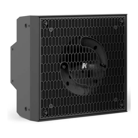
Its steel chassis offers maximum rigidity in a minimum size. The speaker delivers a continuous SPL of 127 dB and has a frequency range of 120 Hz to 19 kHz and it is compatible with all K-array KMT subwoofers. -
Page 5: Safety Information
KX12 Ver. 1.4 4. SAfETY INfoRMATIoN Warning: failure to follow these safety instructions could result in injury or damage to the device or other property. IMPORTANT SAFETY INSTRUCTIONS • Read these instructions. • Keep this instructions. • Heed all warnings. -
Page 6: Unpacking
Ver. 1.4 5. UNPACKING Each K-array speaker is built to the highest standard and thoroughly inspected before leaving the factory. Upon arrival, carefully inspect the shipping carton, then examine and test your new amplifier. If you find any damage, immediately notify the shipping company. Only the consignee may institute a claim procedure regarding the system’s electronic equipment. -
Page 7: Wiring
7. wIRING KX12’s internal wiring is designed to pick up the audio power signal from pins 1+ / 1- of a Speakon NL4 connector. Pins 1+ and 1-, such as pins 2+ and 2-, are directly wired from one socket to the other, so that the two sockets are equivalent and can connect the speaker to the amplifier or to another KX12 driven in parallel by the same amplifier channel. -
Page 8: Horn Orientation
Ver. 1.4 8. hoRN oRIENTATIoN The KX12 features a 12” woofer and a compression driver coupled to an asymmetric horn. Because the horn is asymmetric, its sound dispersion pattern is different in respect to its axes: the sound dispersion is wide along the axis labeled FLOOD and narrow along the axis labeled SPOT. -
Page 9: Rigging
9.1 SUSPENDING ThE KX12 wITh A fLY BAR KX12 units can be suspended using the K-FLY2B, a fly bar; K-FLY22, hardware used to connect the first unit to the fly bar; and K-JOINT2B, the hardware that connects a KX12 to the K-FLY22 or to another KX12. - Page 10 KX12 Ver. 1.4 Join the K-FLY2B and the K-FLY22 with the two 8x40 piston pins provided with the system. Connect the first KX12 unit to the fly bar. Secure with the two 8x40 piston pins provided with the system.
- Page 11 The orientation of the joint blocks and the holes used will affect the angle between the fly bar and the KX12, as shown below. We recommend setting an angle of 0° between the fly bar and the first KX12 unit.
- Page 12 KX12 Ver. 1.4 Position the next unit. Connect the two units with two 8x40 piston pins. Insert the two joints and regulate the angles as explained on the previous page. Secure with four 5x30 piston pins.
- Page 13 KX12 Ver. 1.4 Repeat Step 5 to connect the other units.
-
Page 14: Wall-Mounting The Kx12
KX12 Ver. 1.4 9.2 wALL-MoUNTING ThE KX12 The K-WALL2 accessory is used to mount a KX12 unit to a wall. -
Page 15: Standing The Kx12 On A Kmt Subwoofer
Ver. 1.4 9.3 STANDING ThE KX12 oN A KMT SUBwoofER KX12 units can be mounted on a KMT subwoofer using the K-FOOT2B-202 and the K-JOINT2B accessories. Excellent examples of this combination are the K-array portable stereo systems KRX202, KRX402 and KRX802. - Page 16 Below are the accessories needed to mount the system: K-FOOT2B-202 K-JOINT2B Kit with a K-POLE1 extendable pole Connecting hardware which you will and a K-FLY22 pole adapter. need per KX12 unit. Screw the pole into the subwoofer.
- Page 17 KX12 Ver. 1.4 Insert the K-FLY22 adapter and screw the knob. Connect a K-JOINT2B to each KX12 unit.
- Page 18 KX12 Ver. 1.4 Insert the first KX12 unit. Secure with the two 8x40 piston pins provided with the system. Insert two joint blocks and secure each of them with the two 5x30 piston pins provided with the system. The orientation of the joint blocks and the holes used will affect the angle between the...
- Page 19 KX12 Ver. 1.4 Repeat Steps 4 and 5 to add the other units. The pictures below show how to regulate the angles If you want the to angle the speaker by 0°, +5°, +10° or +15°, position the joint block so that the letter “A”...
-
Page 20: Service
10. SERvICE To obtain service: 1) Contact the official K-array distributor in your country. Your local distributor will direct you to the appropriate service center. 2) If you are calling for service, please have the serial number(s) of the unit(s) available for reference. -
Page 21: Technical Specifications
The contents of this manual are furnished for informational purposes only. K-array s.u.r.l. assumes no responsibility for any errors or inaccuracies that may appear in this manual. K-array s.u.r.l. reserves the right to make modifications without prior notice. -
Page 22: Certification
KX12 Ver. 1.4 12. CERTIfICATIoN...


Need help?
Do you have a question about the KX12 and is the answer not in the manual?
Questions and answers