Table of Contents
Advertisement
Quick Links
Advertisement
Table of Contents

Related Manuals for DeLonghi DGH70ST FSD


Summary of Contents for DeLonghi DGH70ST FSD
- Page 1 Delonghi Instructions for use DGH70ST FSD BUILT-IN 70CM STAINLESS STEEL GAS HOB...
- Page 2 Users Operating Instructions Installation instructions Before operating this hob, please read these instructions carefully DGH 70 ST FSD Built-in cooking hob...
- Page 3 Dear Customer Thank you for choosing one of our appliances which has been carefully designed and built by our specialist staff and thoroughly tested to satisfy your cooking requirement. We suggest that you read this Instruction Booklet so that you will understand fully how to operate the appliances.
- Page 4 Declaration of conformity This hob (Class 3) has been designed for use only as a cooking appliance. ny other use (e.g. heating rooms) should be considered incorrect and therefore dangerous. This hob has been designed, constructed and put on to the market in conformi- ty with: - Safety requirements of EU Directive "Gas"...
-
Page 5: Before Using For The First Time
BEFORE USING FOR THE FIRST TIME Read the instructions carefully before installing and using the appliance • • fter unpacking the appliance, make sure it is not damaged. In case of doubt, do not use the appliance and contact your supplier or a qualified engineer. •... - Page 6 IMPORT NT S FEGU RDS & RECOMMEND TIONS • Do not carry out any cleaning or maintenance without first disconnecting the appli- ance from the electrical supply. • During and after use of the hob, certain parts will become very hot. Do not touch hot parts.
-
Page 7: How To Use Your Gas Hob
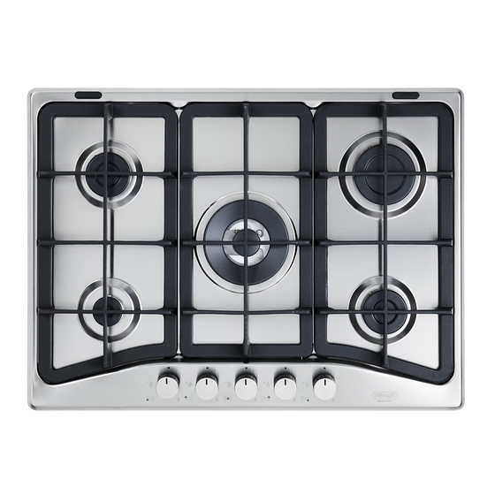
How to use your gas hob Figure 1 This appliance is class 3 COOKING POINTS 1. uxiliary burner ( ) - 1,00 kW 2. Semirapid burner (SR) - 1,75 kW 3. Rapid burner (R) - 3,00 kW 4. Triple-ring burner (TR) - 3,50 kW CONTROL P NEL DESCRIPTION 5. - Page 8 Use of the Hob G S BURNERS Gas flow to the burners is adjusted by turning the knob illustrated in fig. 2 which con- trols the safety valves. Turning the knob so that the indicator line points to the symbols printed on the panel achieves the following functions: full circle closed valve...
-
Page 9: Lighting The Burners
LIGHTING THE BURNERS In order to light the burner, you must: 1 – Press in the corresponding knob and turn counter-clockwise to the full flame posi- tion marked by the symbol (fig. 3) and hold the knob in until the flame has been lit. -
Page 10: Choice Of Burner
CHOICE OF BURNER The burner must be choosen according to the diameter of the pans and energy required. ttention: During use the hob becomes very hot under the cooking zones. Keep children away. Figure 4 P N DI METER BURNER MINIMUM M XIMUM uxiliary... -
Page 11: Correct Use Of Triple-Ring Burner
CORRECT USE OF TRIPLE-RING BURNER The flat-bottomed pans are to be placed directly onto the pan-support. To use the WOK you need to place the proper stand in order to avoid any faulty operation of the triple-ring burner (Fig. 5a). IMPORT NT: The special grille for wok pans (fig. -
Page 12: Cleaning And Maintenance
Cleaning and Maintenance GENER L TIPS Before cleaning the hob switch it off and wait for it to cool down. Clean with a cloth, hot water and soap or liquid detergent. Do not use products which are abrasive, corrosive or chlorine based. Do not use steel pads. - Page 13 BURNERS ND GRIDS These parts can be removed and cleaned with appropriate products. fter cleaning, the burners and their flame spreaders must be well dried and correct- ly replaced. It is very important to check that the burner flame spreader and the cap have been correctly positioned.
- Page 14 CORRECT POSITION OF TRIPLE RING BURNER The triple ring burner must be correctly positioned (see fig. 8); the burner ribs must be fitted in their housing as shown by the arrow. The burner correctly positioned must not rotate (fig. 9). Then position the cap and the ring B (figs.
-
Page 15: Important Notes
Important notes Installation, and any demonstration, information or adjustments are not included in the warranty and, if requested, the customer must pay the after-sale service according to the standard fees. This appliance must be installed and serviced only by a suitably qualified and registered person, and in accordance with the current editions of the relevant standards and reg- ulations or other locally applicable regulations. - Page 16 Do’ s and do not’ s DO’S ND DO NOT’S • Do read the User Instructions carefully before using the hob for the first time. • Do remove spills as soon as they occur. • Do not allow children near the hob when in use. •...
-
Page 17: Installation
Installation IMPORT NT The appliance may be installed in a kitchen, Kitchen/diner or a bed sitting room, but not in a room or space containing a bath or a shower. The appliance must not be installed in a bed-sitting room of less than 20 m The appliance is designed and approved for domestic use only and should not be installed in a commercial, semi commercial or communal environment. - Page 18 TECHNIC L INFORM TION Figure 11 FOR THE INST LLER In order to install the cooktop into the kitchen fixture, a hole with the dimen- sions shown in fig. 12 has to be made, bearing in mind the following: within the unit, between the bottom of the cooktop and the upper sur- face of a shelf there must be a clear- ance of at least 30 mm.
- Page 19 PPLYING THE SE LS Turn the cooktop upside down. Spread the longer seal “ ” around the left, rear and right sides as shown in figure 14a. With a cutter or a scissors cut the excess seal “C” and retain it for next use (figure 14b).
- Page 20 F STENING THE COOKTOP F STENING THE INST LL - TION BR CKETS Insert the cooktop into the hole and position it correctly. Each cooktop is provided with an instal- lation kit including brackets and screws djust the position of the brackets “F for fastening the top to fixture panels and R”...
-
Page 21: Ventilation Requirements
Ventilation requirements The appliance should be installed into a room or space with an air supply in accor- dance with BS 5440-2: 2000. For rooms with a volume of less than 5 m - permanent ventilation of 100 cm free area will be required. -
Page 22: Gas Supply Requirements
Gas supply requirements IMPORT NT NOTE This appliance is supplied for use on N TUR L G S or LPG (check the gas regulation label attached on the appliance). ppliances supplied for use on N TUR L G S: they are adjusted for this gas only and cannot be used on any other gas (LPG) without modification. -
Page 23: Gas Connection
Gas Connection The installation of the gas appliance to Natural Gas or LP Gas must be carried out by a suitably qualified and registered installer. Installers shall take due account of the provisions of the relevant British Standards Code of Practice, the Gas Safety Regulations and the Building Standards (Scotland)(Consolidation) Regulations issued by the Scottish Development Department. - Page 24 G S CONNECTOR Cat: II 2H3+ The fitting (fig. 16) is made up of: 1 nut “ ” 1 elbow fitting “C” gasket “F” CONNECTION TO THE G S SUPPLY Be careful when flexible pipes are used that they do not come into contact with moving parts.
- Page 25 If installation is to be carried out using a flexible connector (to BS669), then the follow- ing points must be adhered to: Note: The gas installation pipes and the final connection to the appliance connecting pipe shall be sufficient size to maintain the heat output of the appliance as specified under installation.
-
Page 26: Conversion To Natural Gas Or Lpg
Conversion to Natural Gas or LPG REPL CING THE BURNER INJECTORS If the N TUR L G S/LPG conversion kit is not supplied with the appliance this kit can be purchased by contacting the fter-Sales Service. Choose the injectors to be replaced according to the table on next page. - Page 27 Table for the choice of the Injectors REDUCED NOMIN L G30/G31 G 20 POWER Cat: 2H3+ POWER 28-30/37 mbar 20 mbar (HS - kW) (HS - kW) Ø injecteur Ø injecteur BURNER [Hs - kW] [Hs - kW] [1/100 mm] [1/100 mm] uxiliary ( ) 1,00...
- Page 28 DJUSTING THE G S BURNER MINIMUM Check whether the flame spreads to all burner ports when the burner is lit with the gas tap set to the minimum position. If some ports do not light, increase the minimum gas rate setting. Check whether the burner remains lit even when the gas tap is turned quickly from the maximum to the minimum position.
-
Page 29: Electrical Connection
Electrical Connection For your safety please read the following information Warning: This appliance must be earthed. The appliance must be connected to a 220-240 volts 50 cycle C supply by means of a three pin socket, suitably earthed and should be protected by a 3 amp fuse in the plug. - Page 30 SECTION OF THE SUPPLY C BLE - TYPE “H05V2V2-F” resistant to temperatures of 90°C 230 V C 50/60 Hz 3 x 0,75 mm The electrical cable must be connected to the terminal board following the diagram of Fig. 22. The appliance must be earthed. The manufacturer declines all responsibility for any problem caused by failure to observe this rule.
- Page 32 Descriptions and illustrations in this booklet are given as simply indicative. The manufacturer reserves the right, considering the characteristics of the models described here, at any time and without notice, to make eventual necessary modifications for their construction or for commercial needs.
- Page 33 od. 1103580 ß2...
Need help?
Do you have a question about the DGH70ST FSD and is the answer not in the manual?
Questions and answers