Table of Contents
Advertisement
Quick Links
Table of Contents
Quick Installation ....................................................... .3
Item Checklist...............................................................................3
Before Installation........................................................................3
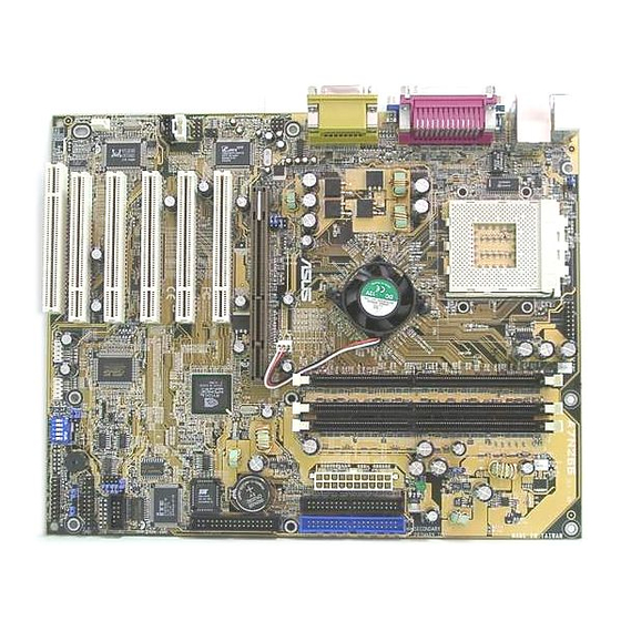
Layout...........................................................................................4
Jumpers/ Connectors..................................................................6
Features ..................................................................... 16
Motherboard Component Placement ...................................... 16
Block Diagram..............................................................................18
Specifications..............................................................................19
Hardware Setup ......................................................... 21
Install the Processor..................................................................21
Install Memory Modules..............................................................22
IWILL 6-Channel Audio/SuperAudio(Optional)..........................23
ATX Power Supply Connector....................................................26
Rear I/O Panel.................................................................................27
FB11324040000
XP333-R/ XP333 Version 1.1
1
Advertisement
Table of Contents

Related Manuals for IWILL XP333


Summary of Contents for IWILL XP333
-
Page 1: Table Of Contents
Before Installation................3 Layout...................4 Jumpers/ Connectors..............6 Features ..............16 Motherboard Component Placement ........16 Block Diagram................18 Specifications................19 Hardware Setup ............21 Install the Processor..............21 Install Memory Modules..............22 IWILL 6-Channel Audio/SuperAudio(Optional)......23 ATX Power Supply Connector............26 Rear I/O Panel.................27 FB11324040000 XP333-R/ XP333 Version 1.1... - Page 2 Advanced BIOS Features ............34 Advanced Chipset Features............37 Integrated Peripherals...............40 Power Management Setup............44 PnP/ PCI Configurations.............47 PC Health Status.................49 IWILL Smart Setting..............49 Load Fail Safe Defaults..............52 Load Optimized Defaults............52 Set Supervisor/ User Password Setting........53 Save & Exit Setup...............54 Exit Without Saving..............54 On Board Audio ............
-
Page 3: Quick Installation
Operation manual ATA 66/100 IDE cable Floppy cable Power Installer CD 6-Channel Audio Port Bracket Optional IWILL SuperAudio (for SPDIF) USB riser kit Thermal Sensor for System Infrared port cable Before Installation Users must follow these guidelines to ensure the motherboard is protected during installation: 1.Make sure your computer is powered-off and unplugged... -
Page 4: Layout
Chapter 1 Quick Installation XP333-R Motherboard Layout JP25 JP10 XP333-R JP31 PCI1 PCI2 PCI3 RAID133 PCI4 JP32 JP20 PCI5 J34A... - Page 5 System Fan Connector Auxiliary Fan Connector Front Panel Connector Infrared Connector Wake-ON-LAN Connector CD-IN Connector SPDIF or 6-Channel Audio Port Bracket Connector [Bracket Optional] Wake-ON-MODEM Connector Please Note: The XP333 motherboard does not have the onboard RAID feature or its connectors.
-
Page 6: Jumpers/Connectors
JP1 controls the Clear CMOS feature. JP32 JP32 controls the onboard RAID feature on the XP333-R. If you have the XP333-R and will use the RAID feature, please refer to the additional RAID Administrator User’s Manual supplied with the XP333-R for infor-... - Page 7 Chapter 1 Quick Installation JP10 4 5 6 4 5 6 4 5 6 1 2 3 1 2 3 1 2 3 2.5V 2.6V 2.7V (Default) JP10 JP10 sets the VIO setting. make sure this is correct for your CPU.
- Page 8 Chapter 1 Quick Installation JP25 Keyboard Power_ON 1 2 3 1 2 3 Enabled Disabled (Default) JP31 Front Side Bus 1 2 3 1 2 3 100MHz 133MHz (Default) JP25 JP25 configures the Keyboard Power On feature in hardware. This must be set to be Enabled for the Keyboard Power On features in the BIOS CMOS Setup Utility to have effect.
- Page 9 Chapter 1 Quick Installation JP20 Audio 1 2 3 1 2 3 Enabled Disabled (Default) 1: VCC 2: NC 3: IR 4: GND 5: IRT JP20 JP20 controls the onboard audio feature. If you want to use an alternate audio expension card, set this to Disabled. J45 is a connector for an optional IR port module.
- Page 10 Chapter 1 Quick Installation J64 6-ch & SPDIF There are two options to upgrade to 6-channel hardware sound 1. IWILL 6-channel Audio (bracket) 2. IWILL SuperAudio (bracket with SPDIF) 6-Channel Audio SuperAudio [SPDIF & 6 Channel (Optional)] 6 CH bracket...
- Page 11 Chapter 1 Quick Installation J54 CD_IN J54 CD_In 1: Left channel 2: GND 3: GND 4: Right channel 4 3 2 1 J34A Externel USB 1: VCC 2: VCC 3: Data- 4: Data- 5: Data+ 6: Data+ 7: GND 8: GND 9: GND J54 is an audio-in connector for an audio cable from an external device with an audio connection such as a CD-ROM drive.
- Page 12 Chapter 1 Quick Installation J46/J69 WOL/WOM 1 2 3 1 2 3 1: 5VSB 1: 5VSB 2: GND 2: GND 3: Control PIN 3: LAN Wake J69 is a connector for the lead from an internal modem that supports the Wake-On-Modem feature.
- Page 13 Chapter 1 Quick Installation J39/J41/J42 FAN 1: GND 2: 12V Fan Aux 3: NC 1: GND 2: 12V Fan CPU 3: Sensor 1: GND 2: 12V Fan Sys 3: Sensor J39 is a power connector for the cooling fan from a heatsink/fan CPU cooler.
- Page 14 Chapter 1 Quick Installation J37 ATX Power Connector XP333-R J37 is a connector for the power connector from a standard ATX power supply.
- Page 15 Chapter 1 Quick Installation J43 Front Panel Connector J43 Front Panel Power_ON 1,13 PIN 3: Anode ACPI LED 3,4 PIN 4: Cathode PIN 7: Anode IDE LED PIN 8: Cathode PIN 11: RST 11,12 Reset PIN 12: GND PIN 15: VCC Power LED 15,16,17 PIN 16: NC PIN 17: GND...
-
Page 16: Features
Chapter2 Feature Features Motherboard Component Placement JP25 JP10 XP333-R JP31 PCI1 PCI2 PCI3 RAID133 PCI4 JP32 JP20 PCI5 J34A... - Page 17 Chapter2 Feature Components CPU Socket DIMM sockets ATX Power connector IDE connectors FDC connector Onboard RAID IDE Connectors (XP333-R) PCI slots AGP slot Rear I/O Panel PS/2 Parallel & 2 Serial Game/MIDI & Audio Mouse Keyboard...
-
Page 18: Block Diagram
Chapter2 Feature Block Diagram Socket 462 CPU ALi M1647 chipset AGP 4X (North Bridge) PCI x 5 IDE Channel x 2 ALi M1535D+ Keyboard & Mouse 6 Channel Sound (South Bridge) USB Port 1&2 IDE RAID Internal USBx2 H/W Monitoring Serial Port x 2 Infrared Port Parallel Port... -
Page 19: Specifications
Chapter2 Feature Specifications Processor I/F (Socket A) -Supports Socket A Processors -Supports 66M/100M/133/166M FSB (Front Side Bus) -Supports Single Athlon / Duron /Athlon XP /Mogon series CPU Frequency/Voltage Select -Supports Vcore Multiplier selection by BIOS(1.050V to 1.825V) -Supports increase 10% CPU Voltage -Supports CPU External Frequency selection (up to 225 MHz) ChipSet (Marking, Packing) North Bridge ALI 1647 VER C... - Page 20 Chapter2 Feature -Supports Power on by Ext. Modem/Int. Modem/RTC/ PME(Wake on Ring) -Supports Resume by Lan/Ext. Modem/Int. Modem/PS2 Keyboard/PS2 Mouse/RTC/PME -Supports ACPI -Supports APM -Supports DMI -Supports SMBUS -Supports PnP -Supports BIOS ROM Flash Control (jumper provides H/W protection) -Supports Manually Assigning PCI IRQs Power Requirements -Onboard DC/DC switching voltage regulator supports Vcore up to 45A current-...
-
Page 21: Hardware Setup
Chapter 3 Hardware Setup Hardware Setup Install the Processor You must install a combination heatsink and fan CPU cooler on top of the CPU after you install it in the CPU socket. The CPU cooler will clip onto the CPU socket in some fashion. Your CPU may have come with a cooler or you may need to buy one separately. -
Page 22: Install Memory Modules
Chapter 3 Hardware Setup Install Memory Modules This motherboard has three DIMM memory sockets and supports up to 3GB of system memory. To install module do as follows. Step 1: Press the DIMM socket retaining latches outward to allow space to insert the module. -
Page 23: Iwill 6-Channel Audio/Superaudio(Optional)
Chapter 3 Hardware Setup IWILL 6Channels Audio/ SuperAudio (Optional) Connectors and Jumpers f i l JP10 function BASS Center channel Center channel BASS channel exChange Default (BASS/Center) Channel 6Channels Audio Front-Speaker Line-IN Game/MIDI 6CH-Audio Rear-Speaker MIC-IN Center/BASS Aud io Ca ble... - Page 24 Chapter 3 Hardware Setup SuperAudio(Optional) Front-Speaker Line-IN Game/MIDI SuperA udio Rear-Speaker MIC-IN Center/BASS RCA SPDIF OUT RCA SPDIF IN Optical SPDIF OUT A u d io Ca b l e Optical SPDIF IN Please remove the cap from the optical cable first...
- Page 25 Chapter 3 Hardware Setup IWILL 6-Channel Audio IWILL SuperAudio (Optional)
-
Page 26: Atx Power Supply Connector
Chapter 3 Hardware Setup ATX Power Supply Connector Power on procedures Step Description After all connections are made, replace the system case cover. Be sure that all switches are off. Connect the power cord into the power supply located on the back of your system case. -
Page 27: Rear I/O Panel
Chapter 3 Hardware Setup Rear I/O Panel Function Color Description PS/2 Mouse Green This connector can be used to support a PS/2 mouse PS/2 keyboard Purple This connector can be used to support a PS/2 keyboard. Black This motherboard has two USB ports, any USB-compatible peripherals and/or hub can be connected into either USB port. -
Page 28: Bios Setup
The BIOS can be upgraded from a diskette with the Award Flash utility — AWDFLASH.EXE. The BIOS image file, and update utility are available from IWILL’s WEB site: support.iwill.net Enter BIOS setup program Power-on the system by either pressing the Power-On button, or by using any of the power-on features provided by the motherboard. - Page 29 Chapter 4 BIOS Setup Using BIOS setup program Move to the previous field Down Move to the next field Left Move to the field on the left hand side Right Move to the field on the right hand side <Esc> Quit from setup program without saving changes,or Exit from current menu page and return to main menu page <PgUp>...
-
Page 30: Main Menu
Chapter 4 BIOS Setup Main Menu The main menu allows you to select from several setup pages. Use the arrow keys to select among these pages and press <Enter> key to enter the sub-menu. A brief description of each highlighted selection appears at the bottom of the screen. - Page 31 Chapter 4 BIOS Setup Date This field specifies the current date. The date format is <day>,<month>, <date>, and <year>. Time This field specifies the current time. The time format is <hour>, <minute>, and <second>. The time is calculated based on the 24-hour (military-time) clock.
- Page 32 Chapter 4 BIOS Setup Drive A / Drive B This field specifies the traditional type of floppy drives. ) t l ) t l Floppy 3 Mode Support 3 Mode floppy drive is a type of 3.5-inch drive used by NEC PC98 computers.
-
Page 33: Base Memory
Chapter 4 BIOS Setup Video The default setting is EGA/VGA. DOn’t chnage it. Halt On l l i l l i l l i , l l l l i , l l l l i , l l Base Memory The POST (Power-On Self Test) determines the amount of base (conventional) memory installed in the system. -
Page 34: Advanced Bios Features
Chapter 4 BIOS Setup Advanced BIOS Features Virus Warning When this function is enabled and any attempt to write data into this area is made, the BIOS monitor will display a warning message on screen and beep. If you want to run an anti-virus program, we recommend you leave this disabled. - Page 35 Chapter 4 BIOS Setup Quick Power On Self Test This field allows the system to skip certain tests while booting. This will decrease the time needed to boot the system. [Enabled(Default Value), Disabled] First / Second / Third / Boot Other Device The BIOS attempts to load the operating system from the devices in the sequence selected in these items.
- Page 36 Chapter 4 BIOS Setup Typematic Rate Setting This field determines if the typematic rate is to be used. When enabled, the BIOS will report (after a moment) that the key has been depressed repeatedly. When disabled, the BIOS will report only once if a key is held down continuously.
-
Page 37: Advanced Chipset Features
Chapter 4 BIOS Setup Advanced Chipset Features This setup page is used to specify advanced features available through the chipset. The default settings have been chosen carefully for most operating conditions. DO NOT change the value of any field in this setup page without knowing what the effect will be. - Page 38 Chapter 4 BIOS Setup DRAM Timing Select The first chipset settings deal with CPU access to dynamic random access memory (DRAM). The default timings have been carefully chosen and should only be altered if data is being lost. Such a scenario might well occur if your system had mixed speed DRAM chips installed.
- Page 39 Chapter 4 BIOS Setup AGP Aperture Size This field configures the main memory size for AGP graphics data used. [1MB, 2MB, 4MB, 8MB, 16MB, 32MB,64MB(Default Value), 128MB, 256MB] I/O Recovery Period This item allows you to determine the recovery time allowed for I/O [0 us, 1 us (Default Value), 2 us, 3 us] Passive Release When enabled, CPU to PCI bus accesses are allowed during pas-...
-
Page 40: Integrated Peripherals
Chapter 4 BIOS Setup Integrated Peripherals On-Chip Primary/Secondary IDE Channel These fields enables or disables the onboard IDE controller channels. [Enable(Default Value), Disabled] PIO & Ultra DMA Settings These fields configure the transfer mode for each IDE device. Use the default Auto setting to automatically detect the best choice. - Page 41 Chapter 4 BIOS Setup On-Chip USB Controller Select Enabled if your system contains USB peripherals. [Enable, Disabled(Default Value)] USB Keyboard Support Select to Enabled if you want to use USB keyboard under DOS. [Enable, Disabled(Default Value)] Init Display First This item allows you to decide which slot to activate first, either PCI slot or AGP slot.
- Page 42 Chapter 4 BIOS Setup KB Power-On Password If you wish to use this function, highlight the field then press <Enter>. The computer will display the message “Enter Pass- word”. Type in a password is displayed and re-type it at the prompt.
- Page 43 Chapter 4 BIOS Setup UART Mode Select [IrDA (Default Value),ASKIR, TFDS6000, HSDL3600, HSDL1100] RxD, TxD Active for IrDA and ASKIR Functions When setting the field to either IrDA or ASKIR, you must select the active level of receiving and transmission signal. [Hi ,Lo(Default Value) /Lo,Hi/Lo,Lo/Hi,Hi] IR Duplex Mode [Full,Half(Default Value)]...
-
Page 44: Power Management Setup
Chapter 4 BIOS Setup Power Management Setup Each power-saving mode has a respective timer. The value of the timer can be assigned or reloaded and it will count down to zero. When the timer equals to zero, the system will be forced into the related suspend or power-saving mode. - Page 45 Chapter 4 BIOS Setup Power Management This feature allows the user to select the default parameters for the power-saving mode. Min Saving: When idle for one hour,the system enters suspend mode. Max Saving: When idle for fifteen minutes, the system enters suspend mode. User Define(Default Value): User can specify the time the system enters suspend mode.
- Page 46 Chapter 4 BIOS Setup Suspend Mode This field specifies the time after which the system enters power- saving mode. It is available only when the Power Management field is set to User Define. [Options: 1Min to 1Hour, Disabled (Default Value)] Soft-Off by PWR-BTTN This field specifies the function of system housing power button.
-
Page 47: Pnp/ Pci Configurations
Chapter 4 BIOS Setup PnP/ PCI Configurations PNP OS Installed The field specifies whether a Plug and Play operating system is installed. [Yes,No(Default Value)] Reset Configuration Data Normally, you leave this field Disabled. Select Enabled to reset Extended System Configuration Data (ESCD) when you exit Setup if you have installed a new add-on cardand the system reconfiguration has caused such a serious conflict that the operating system can not boot. - Page 48 Chapter 4 BIOS Setup Resources Controlled By The Award Plug and Play BIOS has the capacity to automatically configure all of the boot and Plug and Play compatible devices. However, this capability means absolutely nothing unless you are using a Plug and Play operating system such as Windows98/95/ NT.
-
Page 49: Pc Health Status
Chapter 4 BIOS Setup PC Health Status This page displays the results of the hardware monitor checks of the system’s environmental status. On the screen displays CPU/System temperature, FAN speed, and voltages. -
Page 50: Iwill Smart Setting
This is a required default, don’t change it. [Enabled, Disabled (Default Value)] MicroStepping Microstepping another step forward by Iwill to provide users a trouble-free CPU frequency set up procedure. It contains two main functions, Auto Detecting CPU speed and Micro Adjustable CPU FSB speed. - Page 51 Chapter 4 BIOS Setup Micro Adjustable CPU FSB speed IWILL provides a user friendly overclocking function that allows users to experience the fun of overclocking. This function allows user to adjust CPU FSB by 1MHz interval. This is particularly useful when user wants to extract the most out of the purchased CPU.
-
Page 52: Load Fail Safe Defaults
Chapter 4 BIOS Setup Load Fail Safe Defaults When you press <Enter> with this item highlighted, you get a confirma- tion dialog box. Pressing ‘Y’ loads the BIOS default values for the most stable, minimal-performance system operation. Load Optimized Defaults When you press <Enter>... -
Page 53: Set Supervisor/ User Password Setting
Chapter 4 BIOS Setup Set Password Setting These items are used for setting passwords. When a password is set and the Security Option field in Advanced BIOS Features is set to Setup, you will be required to enter the password every time you try to enter the CMOS Setup Utiltiy. -
Page 54: Save & Exit Setup
Chapter 4 BIOS Setup Save & Exit Setup Saves current CMOS values and exits the CMOS Setup Utility. Exit Without Saving Abandons all CMOS value changes and exits the CMOS Setup Utility. -
Page 55: On Board Audio
Chapter 5 On board Audio On Board Audio Audio Features Special Feature 1. Full-duplex playback and recording. Built-in 16-bit CODEC. 2. HRTF 3D positional audio, supporting both DirectSound 3D&A3D interfaces. Also supports earphones, 2/4/6 channel speakers mode. 3. Support Windows 98/Windows 2000 and Windows NT 4.0. 4.Built-in 32 OHM Earphone buffer. - Page 56 Chapter 5 On board Audio Stereo Mixer 1. Stereo analog mixing from CD-Audio and Line-in 2. Stereo digital mixing from Voice, FM/Wave-table, and Digital CD-Audio 3. Mono mixing from MIC. Software adjustable volume. Game and Midi Interface Fully compatible with MPU-401 Midi UART and Sound Blaster Midi mode/Standard IBM PC joystick/game port...
-
Page 57: Driver Installation
Chapter 5 On board Audio Driver Installation DOS Installation Before beginning the installation, please make sure that your hard disk has sufficient space(min. 4MB). Insert the Power Installer CD into the CD-ROM Drive. 1. Change directory to PCI audio DOS drivers folder (ex. - Page 58 Chapter 5 On board Audio Windows NT4.0 Installation We recommend that you have Microsoft Windows NT intalled, and remove any exsisting sound drivers from your current system, before you install this PCI sound device driver. 1. Click “Start” , move the highlight bar to “Setting”, and select “Control Panel”.
-
Page 59: The Audio Rack
Chapter 5 On board Audio The Audio Rack Introduction By means of a user-friendly interface that is as easy as operating your home stereo system, the Audio Rack software provides you with control over your PC’s audio functions, including the advan- tage of 6-speaker mode enable/ disable, and digital sound (SPDIF version ONLY) input/output. - Page 60 Chapter 5 On board Audio Mixer Volume Control For each output signal, the vertical control slider regulates the vol- ume and the horizontal slider the balance between two speakers. The mute button temporarily stops audio output without changing slider positions. When a button LED is lit, that audio output is available. Several output signals can usually be enabled at once.
-
Page 61: Installing Support Software
Chapter 5 On board Audio Installing Support Software This section covers installing Operating System software and the support software on the Power Installer support CD-ROM disc. Once you have configured the CMOS Setup Utility, you should install an OS. If you install a supported Microsoft OS, you should also install the driver software on the Power Installer disc. - Page 62 Chapter 5 On board Audio Installing Windows Drivers This section assumes you have installed one of the supported Microsoft Operating Systems on the system hard disk drive. To install Windows drivers, insert the Power Installer support CD- ROM disc in the system’s CD-ROM (or other optical drive) and wait for the Power Installer interface to automatically load.
- Page 63 Chapter 5 On board Audio...
- Page 64 Chapter 5 On board Audio The following screen will appear when you click on Manual Installa- tion. Click on “Driver Installation” and the Driver Installation screen will appear.
- Page 65 Rage 128 Pro display card, also install the “Patch Driver”. Next install the “Onboard Audio Driver” in the same way. Finally, if you have the XP333-R with the onboard RAID feature, to configure a RAID array, please review and follow the Raid Adminis- trator User’s Manual by clicking on the “Onboard RAID Driver Intsall...
- Page 66 Chapter 5 On board Audio The Make Driver Utility The “Make Driver” utility makes driver floppy disks. You can floppy disk copies of the ALi chipset support software and the Onboard HighPoint 370A/372 RAID Driver and Utility.
- Page 67 Chapter 5 On board Audio Making & Installing Linux Drivers You can boot the system from the Power Installer disc. The system will boot from the Linux kernel on the disc and you can use the disk creator that loads to create Linux support disks. You can then use these to install any necessary modules according to your Linux distribution’s instructions for module installation.
- Page 68 Chapter 5 On board Audio...
Need help?
Do you have a question about the XP333 and is the answer not in the manual?
Questions and answers