Table of Contents
Advertisement
Copyright
This publication, including all photographs, illustrations and software, is protected
under international copyright laws, with all rights reserved. Neither this manual, nor
any of the material contained herein, may be reproduced without written consent of
the author.
Version 2.0
Disclaimer
The information in this document is subject to change without notice. The manufac-
turer makes no representations or warranties with respect to the contents hereof and
specifically disclaims any implied warranties of merchantability or fitness for any
particular purpose. The manufacturer reserves the right to revise this publication and
to make changes from time to time in the content hereof without obligation of the
manufacturer to notify any person of such revision or changes.
Trademark Recognition
Microsoft, MS-DOS and Windows are registered trademarks of Microsoft Corp.
MMX, Pentium, Pentium-II, Pentium-III, Celeron are registered trademarks of Intel
Corporation.
Other product names used in this manual are the properties of their respective
owners and are acknowledged.
Federal Communications Commission (FCC)
This equipment has been tested and found to comply with the limits for a Class B
digital device, pursuant to Part 15 of the FCC Rules. These limits are designed to
provide reasonable protection against harmful interference in a residential installa-
tion. This equipment generates, uses, and can radiate radio frequency energy and, if
not installed and used in accordance with the instructions, may cause harmful inter-
ference to radio communications. However, there is no guarantee that interference
will not occur in a particular installation. If this equipment does cause harmful
interference to radio or television reception, which can be determined by turning the
equipment off and on, the user is encouraged to try to correct the interference by one
or more of the following measures:
•
Reorient or relocate the receiving antenna
•
Increase the separation between the equipment and the receiver
•
Connect the equipment onto an outlet on a circuit different from that to
which the receiver is connected
•
Consult the dealer or an experienced radio/TV technician for help
Shielded interconnect cables and a shielded AC power cable must be employed with
this equipment to ensure compliance with the pertinent RF emission limits govern-
ing this device. Changes or modifications not expressly approved by the system's
manufacturer could void the user's authority to operate the equipment.
Preface
Preface
Advertisement
Table of Contents

Related Manuals for ECS P43T-A2


Summary of Contents for ECS P43T-A2
- Page 1 Preface Copyright This publication, including all photographs, illustrations and software, is protected under international copyright laws, with all rights reserved. Neither this manual, nor any of the material contained herein, may be reproduced without written consent of the author. Version 2.0 Disclaimer The information in this document is subject to change without notice.
-
Page 2: Declaration Of Conformity
Declaration of Conformity This device complies with part 15 of the FCC rules. Operation is subject to the following conditions: • This device may not cause harmful interference, and • This device must accept any interference received, including interfer- ence that may cause undesired operation Canadian Department of Communications This class B digital apparatus meets all requirements of the Canadian Interference- causing Equipment Regulations. -
Page 3: Table Of Contents
T T T T T ABLE OF CONTENTS ABLE OF CONTENTS ABLE OF CONTENTS ABLE OF CONTENTS ABLE OF CONTENTS Preface Chapter 1 1 1 1 1 1 Introducing the Motherboard Introduction..................1 Feature ....................2 Motherboard Components.............4 Chapter 2 7 7 7 7 7 Installing the Motherboard Safety Precautions................7 Choosing a Computer Case............7... - Page 4 Integrated Peripherals............32 Power Management Setup..........33 PCI/PnP Setup..............34 PC Health Status..............35 Frequency/Voltage Control..........36 Load Default Settings............38 Supervisor Password............38 User Password..............39 Save & Exit Setup...............40 Exit Without Saving............40 Updating the BIOS.............40 Chapter 4 41 41 41 41 41 Using the Motherboard Software About the Software DVD-ROM/CD-ROM........41 Auto-installing under Windows XP/Vista/7.......41 Running Setup..............42...
-
Page 5: Introducing The Motherboard
Chapter 1 Introducing the Motherboard Introduction Thank you for choosing the P43T-A2 motherboard. This motherboard is a high performance, enhanced function motherboard designed to support the LGA775 socket ® Intel Yorkfield/Wolfdale processors for high-end business or personal desktop mar- kets. The motherboard incorporates the Intel Eaglelake P43 Northbridge (NB) and Intel ICH10 Southbridge (SB) chipsets. -
Page 6: Feature
Feature Processor ® Yorkfield/Wolfdale This motherboard uses an LGA775 type of Intel that carries the following features: • Accommodates Intel ® Yorkfield/Wolfdale processors • Supports a system bus (FSB) of 1333/1066/800 MHz Chipset The P43 Northbridge (NB) and ICH10 Southbridge (SB) chipsets are based on an innovative and scalable architecture with proven reliability and performance. -
Page 7: Onboard Lan
Onboard LAN • Integrated 10/100/1000 Base-T Transceiver • Integrated 10/100/1000 Mbps IEEE 802.3 compliant • IEEE 802.3u Auto-Negotiation Expansion Options The motherboard comes with the following expansion options: • One PCI Express x16 slot for Graphics Interface • Three PCI Express x1 slots •... -
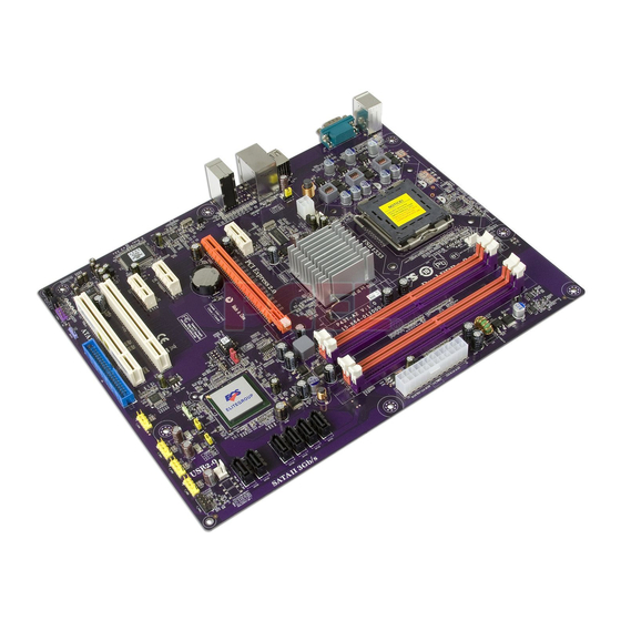
Page 8: Motherboard Components
Motherboard Components Introducing the Motherboard... - Page 9 Table of Motherboard Components LABEL CO MPO NENTS ® LGA775 socket Intel Yorkfield/Wolfdale 1. CPU Socket Family processors 2. CPU_FAN1 CPU cooling fan connector 3. DDR2_DIMM1~4 240-pin DDR2 SDRAM slots 4. ATX_POWER Standard 24-Pin ATX Power connector 5. SATA1~6 Serial ATA connectors 6.
- Page 10 Memo Introducing the Motherboard...
-
Page 11: Installing The Motherboard
Chapter 2 Installing the Motherboard Safety Precautions • Follow these safety precautions when installing the motherboard • Wear a grounding strap attached to a grounded device to avoid dam- age from static electricity • Discharge static electricity by touching the metal case of a safely grounded object before working on the motherboard •... -
Page 12: Checking Jumper Settings
Do not over-tighten the screws as this can stress the motherboard. Checking Jumper Settings This section explains how to set jumpers for correct configuration of the motherboard. Setting Jumpers Use the motherboard jumpers to set system configuration options. Jumpers with more than one pin are numbered. -
Page 13: Checking Jumper Settings
Checking Jumper Settings The following illustration shows the location of the motherboard jumpers. Pin 1 is labeled. Jumper Settings Jumper Type Description Setting (default) 1-2: NORMAL 2-3: CLEAR CLR_CMOS 3-pin CLEAR CMOS Before clearing the CMOS, make sure to CLR_CMOS turn the system off. -
Page 14: Installing Hardware
Installing Hardware Installing the Processor Caution: When installing a CPU heatsink and cooling fan make sure that you DO NOT scratch the motherboard or any of the surface-mount resis- tors with the clip of the cooling fan. If the clip of the cooling fan scrapes across the motherboard, you may cause serious damage to the motherboard or its components. -
Page 15: Cpu Installation Procedure
CPU Installation Procedure The following illustration shows CPU installation components. A. Read and follow the instructions shown on the sticker on the CPU cap. B. Unload the cap · Use thumb & forefinger to hold the lifting tab of the cap. ·... -
Page 16: Installing Memory Modules
Installing Memory Modules This motherboard accommodates four memory modules. It can support four 240-pin DDR2 800/667. The total memory capacity is 16 GB. DDR2 SDRAM memory module table Memory module Memory Bus DDR2 333 MHz DDR2 400 MHz You must install at least one module in any of the four slots. Each module can be installed with 4 GB of memory;... - Page 17 Table A: DDR2 (memory module) QVL (Qualified Vendor List) The following DDR2 800/667/533 memory modules have been tested and qualified for use with this motherboard. Type Size Vendor Module Name Samsung PC2-4200U-4444-10-B1 512 MB DDR2 533 A-data A-DATA/Vitesta 1 GB Kingmax KLBD48F-A8KE4 Apacer...
- Page 18 Type Size Vendor Module Name KVR800D2N5/512 1.8V Kingston 9905315-019.A02LF 512 MB Micron MT8HTF6464AY-80ED4 Qimonda HYS72T64000HU-2.5-B A-DATA M2GVD6G3I41P0U1E5E AET760UD00-30DB97X Aeneon AET760UD00-25DC08X AU01GE800C5KBGC Apacer 78.01GAO.9K5 APOGEE AU1G082-800P000 Geil Millenary /Geil/GL2L64M088BA18H Geil Geil Platinum Edition Geil/Boxed Hexon ELPT7AUDR-25M48 1 GB Infinity 04701G16CZ5U2G KHX6400D2ULK2/2G 9905315- 078.A00LF//Boxed Kingston KVR800D2N5/1G 1.8V...
-
Page 19: Expansion Slots
Expansion Slots Installing Add-on Cards The slots on this motherboard are designed to hold expansion cards and connect them to the system bus. Expansion slots are a means of adding or enhancing the motherboard’s features and capabilities. With these efficient facilities, you can in- crease the motherboard’s capabilities by adding hardware that performs tasks that are not part of the basic system. - Page 20 Follow these instructions to install an add-on card: Remove a blanking plate from the system case corresponding to the slot you are going to use. Install the edge connector of the add-on card into the expansion slot. Ensure that the edge connector is correctly seated in the slot. Secure the metal bracket of the card to the system case with a screw.
-
Page 21: Connecting Optional Devices
Connecting Optional Devices Refer to the following for information on connecting the motherboard optional devices F_AUDIO: Front Panel Audio header This header allows the user to install auxiliary front-oriented microphone and line- out ports for easier access. Signal Name Signal Name Signal Name Function PORT 1L... - Page 22 F_USB1~4: Front Panel USB headers The motherboard has four USB ports installed on the rear edge I/O port array. Additionally, some computer cases have USB ports at the front of the case. If you have this kind of case, use auxiliary USB connector to connect the front-mounted ports to the motherboard.
-
Page 23: Installing A Hard Disk Drive/Cd-Rom/Sata Hard Drive
Installing a Hard Disk Drive/CD-ROM/SATA Hard Drive This section describes how to install IDE devices such as a hard disk drive and a CD- ROM drive. About IDE Devices Your motherboard has one IDE interface. IDE: IDE Connector This motherboard supports six high data transfer SATA ports with each runs up to 3.0 Gb/s. - Page 24 Refer to the illustration below for proper installation: Attach either cable end to the connector on the motherboard. Attach the other cable end to the SATA hard drive. Attach the SATA power cable to the SATA hard drive and connect the other end to the power supply.
-
Page 25: Connecting I/O Devices
Connecting I/O Devices The backplane of the motherboard has the following I/O ports: PS2 Mouse Use the upper PS/2 port to connect a PS/2 pointing device. PS2 Keyboard Use the lower PS/2 port to connect a PS/2 keyboard. Serial Port Use the COM port to connect serial devices such as mice or (COM) fax/modems. -
Page 26: Connecting Case Components
Connecting Case Components After you have installed the motherboard into a case, you can begin connecting the motherboard components. Refer to the following: Connect the CPU cooling fan cable to CPU_FAN1. Connect the system cooling fan connector to SYS_FAN1. Connect the case cooling fan connector to CASE_FAN. Connect the standard power supply connector to ATX_POWER. -
Page 27: Atx 12V Power Connector
CPU_FAN1/SYS_FAN1: Cooling FAN Power Connector Signal Name Function System Ground Power +12V +12V Sense Sensor Control CPU FAN control Users please note that the fan connector supports the CPU cooling fan of 1.1A ~ 2.2A (26.4W max) at +12V. CASE_FAN: Case cooling FAN Power Connector Signal Name Function System Ground... -
Page 28: Front Panel Header
Front Panel Header The front panel header (F_PANEL) provides a standard set of switch and LED headers commonly found on ATX or Micr ATX cases. Refer to the table below for informa- tion: Signal Function Signal Function HD_LED_P Hard disk LED (+) 2 FP PWR/SLP *MSG LED (+) HD_LED_N Hard disk LED (-) FP PWR/SLP *MSG LED (-) -
Page 29: Using Bios
Chapter 3 Using BIOS About the Setup Utility The computer uses the latest “American Megatrends Inc. ” BIOS with support for Windows Plug and Play. The CMOS chip on the motherboard contains the ROM setup instructions for configuring the motherboard BIOS. The BIOS (Basic Input and Output System) Setup Utility displays the system ’... -
Page 30: Using Bios
Press the delete key to access the BIOS Setup Utility. CMOS Setup Utility -- Copyright (C) 1985-2008, American Megatrends, Inc. Standard COMS Setup Frequency/Voltage Control Load Default Settings Advanced Setup Advanced Chipset Setup Supervisor Password Integrated Peripherals User Password Power Management Setup Save &... -
Page 31: Standard Cmos Setup
For the purpose of better product maintenance, the manufacture reserves the right to change the BIOS items presented in this manual. The BIOS setup screens shown in this chapter are for reference only and may differ from the actual BIOS. Please visit the manufacture’s website for updated manual. Standard CMOS Setup This option displays basic information about your system. - Page 32 Type (Auto) Use this item to configure the type of the IDE device that you specify. If the feature is enabled, it will enhance hard disk performance by reading or writing more data during each transfer. LBA/Large Mode (Auto) Use this item to set the LBA/Large mode to enhance hard disk performance by optimizing the area the hard disk is visited each time.
-
Page 33: Advanced Setup
Enabled 1st Boot Device Hard Drive 2nd Boot Device CD/DVD 3rd Boot Device Remvable Dev. Boot Other Device ECS eJIFFY Function Disabled : Move Enter : Select < > +/-/: Value F10: Save ESC: Exit F1: General Help F9: Load Default settings... - Page 34 ECS eJIFFY Function (Disabled) Use this item to enable or disable the ECS eJIFFY Function. eJIFFY is ECS unique software program for the quick access to the internet without entering O.S. Please refer to Chapter 5 to know more about eJIFFY.
-
Page 35: Advanced Chipset Setup
Advanced Chipset Setup This page sets up more advanced information about your system. Handle this page with caution. Any changes can affect the operation of your computer. CMOS Setup Utility - Copyright (C) 1985-2008, American Megatrends, Inc. Advanced Chipset Setup Help Item DRAM Frequency Auto... -
Page 36: Integrated Peripherals
Integrated Peripherals This page sets up some parameters for peripheral devices connected to the system. CMOS Setup Utility - Copyright (C) 1985-2008, American Megatrends, Inc. Integrated Peripherals Onboard SATA Mode Enhanced Help Item Onboard LAN Function Enabled Onboard LAN Boot ROM Disabled Options Onboard AUDIO Function... -
Page 37: Power Management Setup
Power Management Setup This page sets up some parameters for system power management operation. CMOS Setup Utility - Copyright (C) 1985-2008, American Megatrends, Inc. Power Management Setup Help Item ACPI Suspend Type S3 (STR) Soft-off by PWR-BTTN Instant Off Select the ACPI PWRON After PWR-Fail Power Off state used for... -
Page 38: Pci/Pnp Setup
Resume By PS2 KB (S3) (Disabled) This item enables or disables you to allow keyboard activity to awaken the system from S3 mode. Resume By PS2 MS (S3) (Disabled) This item enables or disables you to allow mouse activity to awaken the system from S3 mode. -
Page 39: Pc Health Status
PC Health Status On motherboards support hardware monitoring, this item lets you monitor the parameters for critical voltages, temperatures and fan speeds. CMOS Setup Utility - Copyright (C) 1985-2008, American Megatrends, Inc. PC Health Status Help Item -=- System Hardware Monitor -=- Smart Fan Function Press Enter Shutdown Temperature... -
Page 40: Frequency/Voltage Control
Shutdown Temperature(Disabled) Enable you to set the maximum temperature the system can reach before powering down. System Component Characteristics These items display the monitoring of the overall inboard hardware health events, such as System & CPU temperature, CPU & DIMM voltage, CPU & system fan speed,...etc. - Page 41 Over-clocking Function. (Disabled) This item decides the CPU over-clocking function/frequency installed in your sys- tem. If the over-clocking fails, please turn off the system power. And then, hold the PageUp key ( similar to the Clear CMOS function) and turn on the power, the BIOS will recover the safe default.
-
Page 42: Load Default Settings
Load Default Settings This option opens a dialog box to ask if you are sure to install optimized defaults or not. You select [OK], and then <Enter>, the Setup Utility loads all default values; or select [Cancel], and then <Enter>, the Setup Utility does not load default values. Supervisor Password This page helps you install or change a password. -
Page 43: User Password
User Password This page helps you install or change a password. CMOS Setup Utility - Copyright (C) 1985-2008, American Megatrends, Inc. User Password User Password : Not Installed Help item Change User Password Press Enter Install or Change the password. <... -
Page 44: Updating The Bios
Updating the BIOS You can download and install updated BIOS for this motherboard from the manufacturer’s Web site. New BIOS provides support for new peripherals, improve- ments in performance, or fixes for known bugs. Install new BIOS as follows: If your motherboard has a BIOS protection jumper, change the setting to allow BIOS flashing. -
Page 45: Using The Motherboard Software
Chapter 4 Using the Motherboard Software About the Software DVD-ROM/CD-ROM The support software DVD-ROM/CD-ROM that is included in the motherboard pack- age contains all the drivers and utility programs needed to properly run the bundled products. Below you can find a brief description of each software program, and the location for your motherboard version. -
Page 46: Running Setup
Drivers Tab Setup Click the Setup button to run the software installation program. Select from the menu which software you want to install. Browse CD The Browse CD button is the standard Windows command that allows you to open Windows Explorer and show the contents of the support disk. - Page 47 Click Next. The following screen appears: Check the box next to the items you want to install. The default options are recom- mended. Click Next run the Installation Wizard. An item installation screen appears: Follow the instructions on the screen to install the items. Drivers and software are automatically installed in sequence.
-
Page 48: Manual Installation
Windows Vista/7 will appear below UAC (User Account Control) message after the system restart. You must select “Allow” to install the next driver. Continue this process to complete the drivers installation. Manual Installation Insert the disk in the DVD-ROM/CD-ROM drive and locate the PATH.DOC file in the root directory. -
Page 49: Setting Up Ejiffy
Note: eJIFFY is ECS optional feature utility corresponding to the DVD activation and BIOS setup. Please check the hard copy user’s guide or product color-box to see if the model has embodded eJIFFY feature. -
Page 50: Installation And Bios Setup
DVD Activation Finish the DVD utility setup, and then set the BIOS to complete eJIFFY activation. 1. Insert ECS software utility DVD and enter below “Utilities” screen. Click eJIFFY feature item to install. 2. Follow the onscreen instructions to finish eJIFFY setup. - Page 51 3. After setting up eJIFFY under Windows, you can switch eJIFFY display/keyboard language from English to your local language. The changes will be applied after rebooting. Note: The keyboard language selection list offers several more regional keyboard setups to switch with the default English typing. Please refer to the usage FAQ for more tips.
- Page 52 Setup button on the post screen to enter the BIOS setup page after boot up. 5. And then enter the Advanced Setup page to enable the item ECS eJIFFY Func- tion. Press F10 to save the configuration and exit. Restart your computer.
-
Page 53: Entering Ejiffy
Entering eJIFFY The post screen appears within several seconds after boot up and it has three buttons on it, Operating system, eJIFFY and BIOS Setup. Click to enter the normal OS you have installed such as Windows. Click to enter eJIFFY OS. Click to set the BIOS. -
Page 54: Features Icons
Feature Icons The following illustration shows the main feature icons that eJIFFY provides on the menu. eWeb: Firefox for web browsing/webmail and watching flash video. ePix: Photo viewing. ePal: On-line chat tool to use the most popular IMs in the world. (MSN, ICQ , AIM, etc.) Shows ePal on-line connection status. -
Page 55: Usage Faq
Usage FAQ Language Control Panel: Besides setting English as the default interface, eJIFFY offers multi-language displays and keyboard settings for language- switch. Open the language control panel to select a preferable language setting. Keyboard Language Setup Step1. Click to open the language control panel. Step 2: Click “Keyboard Language”... - Page 56 Click to enable all possible language inputs you want to apply, and click “Apply”: Move your mouse pointer on the text box and press Ctrl+Space. The language bar will then appear as fol- lows. Click the language bar here. Select your desired language Setting Up eJIFFY...
- Page 57 How to change display language? Open the Language Control Panel and click to show the display language list. Check your desired display language. Your selected display language will be applied after rebooting. Note: Details about eJIFFY please refer to eJIFFY in disk. Setting Up eJIFFY...
- Page 58 Memo Setting Up eJIFFY...
-
Page 59: Trouble Shooting
Chapter 6 Trouble Shooting Start up problems during assembly After assembling the PC for the first time you may experience some start up problems. Before calling for technical support or returning for warranty, this chapter may help to address some of the common questions using some basic troubleshooting tips. -
Page 60: Start Up Problems After Prolong Use
c) The PC suddenly shuts down while booting up. 1. The CPU may experience overheating so it will shutdown to protect itself. Ensure the CPU fan is working properly. 2. From the BIOS setting, try to disable the Smartfan function to let the fan run at default speed. - Page 62 Memo Trouble Shooting...
Need help?
Do you have a question about the P43T-A2 and is the answer not in the manual?
Questions and answers