
Subscribe to Our Youtube Channel
Related Manuals for WTI NBB-1600


Summary of Contents for WTI NBB-1600
- Page 1 WTI Part No.: 13406 Rev. B NBB-1600 Series Network Boot Bars Models: NBB-1600 & NBB-1600-CE Firmware Version: 1.41 and Higher User’s Guide...
-
Page 3: Warnings And Cautions
Warnings and Cautions: INSTALLATION INSTRUCTIONS SECURE RACKING If Secure Racked units are installed in a closed or multi-unit rack assembly, they may require further evaluation by Certification Agencies. The following items must be considered. The ambient within the rack may be greater than room ambient. Installation should be such that the amount of air flow required for safe operation is not compromised. - Page 4 NBB-1600 Series: Network Boot Bars - User's Guide FCC Part 15 Regulation This equipment has been tested and found to comply with the limits for a Class A digital device, pursuant to Part 15 of the FCC rules. These limits are designed to provide reasonable protection against harmful interference in a residential installation.
-
Page 5: Table Of Contents
Table of Contents Introduction ............1-1 Unit Description . -
Page 6: List Of Figures
2.1. NBB Unit (Model NBB-1600 Shown) ........ -
Page 7: Introduction
The NBB is built in the USA and backed by a two year warranty. NetReach products are installed in thousands of network sites world wide. Our customers know they can depend on WTI for superior quality and reliability for their most mission-critical operations. -
Page 8: Typographic Conventions
This User’s Guide discusses both the 115 VAC and 230 VAC versions of the NBB-1600 Network Boot Bar. Throughout this User’s Guide, both units are referred to as "NBB". The NBB-1600 is intended for 115 VAC operation, and can switch up to 15 Amps per power circuit (30 Amps total). The NBB-1600-CE is intended for 230 VAC operation, and can switch up to 10 Amps per power circuit (20 amps total.) Aside from voltage and load... -
Page 9: Unit Description
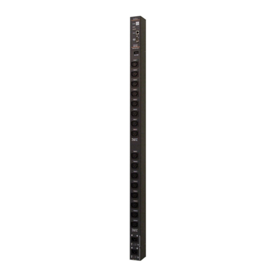
2. Unit Description As shown in Figure 2.1, the NBB-1600 unit includes power outlets, LEDs and a manual control button. The items in Figure 2.1 are described on the following page. Figure 2.1: NBB Unit (Model NBB-1600 Shown) - Page 10 Switched Plugs and Plug Indicators: • Model NBB-1600: Sixteen (16) 115 VAC outlets, split into two separate power circuits. Each power circuit can switch a total load of up to 15 Amps. Circuit "A" includes plugs 1 through 8, and Circuit "B"...
-
Page 11: Quick Start
Circuit "B" inlets, and then connect the cables to an appropriate power supply. The NBB-1600 will support up to 15 Amps maximum per power circuit, for a total load of 30 Amps. The NBB-1600-CE will support up to 10 Amps maximum per power circuit, for a total load of 20 Amps. -
Page 12: Communicating With The Nbb
NBB-1600 Series: Network Boot Bars - User's Guide When the NBB is shipped from the factory, RS232 Port Parameters are set as follows: 9600 bps, 8 Data Bits, One Stop Bit, No Parity. Although the NBB allows these parameters to be easily redefined, for the purpose of this Quick Start procedure, it is recommended that you configure your communications... -
Page 13: Plug Status Screen - Web Browser Interface
Quick Start Figure 3.1: Plug Status Screen - Web Browser Interface Network Boot Bar v1.41c Site ID: (undefined) Plug | Name | Password | Status | Boot/Seq. Delay | Default | -----+------------------+-------------+--------+-----------------+---------+ | (undefined) | (undefined) 0.5 Secs | (undefined) | (undefined) 0.5 Secs | (undefined) - Page 14 Web Browser Interface: Click on the "Log Out" button. b) Text Interface: Type /X and press [Enter]. This completes the Quick Start Guide for the NBB-1600 Series Network Boot Bar. Prior to placing the unit into operation, it is recommended to refer to the remainder of this User’s Guide for important information regarding advanced...
-
Page 15: Installation
"A" (plugs 1 to 8) can switch up to 15 amps total, and Power Circuit "B" (plugs 9 to 16) can also switch up to 15 Amps total. The NBB-1600-CE is designed for 230 VAC power control; Power Circuit "A" (plugs 1 to 8) can switch up to 10 amps total, and Power Circuit "B"... -
Page 16: Console Port Connection
NBB-1600 Series: Network Boot Bars - User's Guide 4.3. Console Port Connection The Console Port is a male, RS232C DB9 connector, wired in a DTE configuration similar to an AT computer. In the default state, the Console port is configured for 9600 bps, no parity, 8 data bits, 1 stop bit. The Console Port can be connected to either an external modem or a local PC, but not both items at the same time. -
Page 17: Configuration
5. Configuration 5.1. System Mode and User Mode In order to restrict access to sensitive command functions, the NBB features two operating modes; System Mode and User Mode. • System Mode: Allows access to all configuration menus, switching functions and status screens. The System Mode Status Screens show On/Off conditions for all switched outlets, and list all currently defined system parameters. -
Page 18: Communicating With The Nbb
NBB-1600 Series: Network Boot Bars - User's Guide Figure 5.1: Plug Status Screen - Web Browser Interface (Sample Values Show) 5.2. Communicating with the NBB In order to configure the unit or invoke command functions, you must first connect to the NBB and access the command mode. As discussed in Section 3, the NBB offers two separate command interfaces: the Web Browser Interface, and the Text Interface. -
Page 19: Accessing The Web Browser Interface
Confi guration 5.2.1. Accessing the Web Browser Interface In order to issue commands via the Web Browser Interface, the NBB must be connected to a TCP/IP network, and your PC must be equipped with a JavaScript enabled web browser (such as Internet Explorer or Netscape Navigator.) 1. -
Page 20: Accessing The Text Interface
NBB-1600 Series: Network Boot Bars - User's Guide Network Boot Bar v1.41c Site ID: (undefined) Plug | Name | Password | Status | Boot/Seq. Delay | Default | -----+------------------+-------------+--------+-----------------+---------+ | Server_1 | (defined) 15 Secs | Server_2 | (defined) 15 Secs | Server_3 | (defined) - Page 21 Confi guration c) Via Network: The NBB includes a default IP address (192.168.168.168), which allows you to contact the unit from any network node on the same subnet. When the NBB is installed in a working network environment, it is recommended that you redefine the IP Address, Subnet Mask, and Gateway Address as described in Section 5.3.4.
-
Page 22: Configuration Menus
NBB-1600 Series: Network Boot Bars - User's Guide 5.3. Configuration Menus As described in the sections that follow, configuration parameters for the NBB can be selected via the Web Browser Interface or Text Interface. Although the Web Browser and Text Interface provide two separate means for selecting... -
Page 23: General Parameters Menu - Web Browser Interface
Confi guration Figure 5.3: General Parameters Menu - Web Browser Interface GENERAL PARAMETERS: System Password: (undefined) User Name: (undefined) Site ID: (undefined) Command Echo: Inactivity Timeout: 2 Mins Command Confirmation: On Automated Mode: Manual Switch Button: On Command Prompt: Default Parameters Enter Selection, Press <ESC>... - Page 24 NBB-1600 Series: Network Boot Bars - User's Guide The General Parameters Menu allows the following parameters to be defined. System Password: The NBB will display a password prompt when • you attempt to access command mode. When the System Password is entered at log on, the System Mode will be active, allowing access to both switching functions and configuration menus.
- Page 25 Confi guration • Inactivity Timeout: Determines how long the NBB will wait for additional commands during periods of inactivity. When the Timeout Period elapses, the user will be disconnected from the NBB command mode. (Default = 2 Minutes.) • Command Confirmation: When enabled, the NBB will display a confirmation prompt before executing certain commands.
-
Page 26: The Serial Parameters Menu
NBB-1600 Series: Network Boot Bars - User's Guide Figure 5.5: Serial Parameters Menu - Web Browser Interface SERIAL PARAMETERS: 1. Baud Rate: 9600 2. Data: 8 Bit 3. Parity: None 4. Stop: 1 Bit 5. Port Mode: Console 6. Modem Init. Str: ATE0M0Q1&C1&D2S0=1 Enter selection, Press <ESC>... - Page 27 Confi guration As shown in Figure 5.5 and Figure 5.6, the Serial Parameters Menus allow you to define the following parameters: Note: When the baud rate, data bits, parity or stop bits settings are changed via the console port, newly selected parameters will not be applied until the user exits and then re-enters command mode.
-
Page 28: The Plug Parameters Menus
NBB-1600 Series: Network Boot Bars - User's Guide Figure 5.7: Plug Parameters Menu - Web Browser Interface PLUG #1 PARAMETERS: 1. Plug Name: Server_1 2. Password: (undefined) 3. Boot/Seq. Delay: 0.5 Secs 4. Power Up Default: Enter Selection, Press <ESC> to Exit ... - Page 29 Confi guration Note that when defining plug parameters via the Web Browser Interface, the desired plug is selected using the dropdown menu at the top of the page. When defining plug parameters via the Text Interface, the plug is selected using the /P n command (where n is the number or name of the desired plug.) The Plug Parameters Menu allows the following parameters to be defined: •...
-
Page 30: Plug Passwords And Co-Location Features
NBB-1600 Series: Network Boot Bars - User's Guide 5.3.3.1. Plug Passwords and Co-Location Features The Plug Passwords, which are defined via the Plug Parameters Menu(s) allow you to determine which plugs an individual user will be permitted to control. When a plug password is entered while logging into command mode, the user will be able to issue switching and reboot commands for the corresponding plug, and every other plug that shares this same password. -
Page 31: The Boot / Sequence Delay Period
Confi guration 5.3.3.2. The Boot / Sequence Delay Period. The Boot / Sequence Delay value will be applied differently for Reboot operations as opposed to simple On/Off operations as described below: 1. Reboot Cycles: a) Single Plug: The Boot/Seq. Delay determines how long the plug will remain Off before it is switched back On again. -
Page 32: Network Parameters Menus
NBB-1600 Series: Network Boot Bars - User's Guide 5.3.4. Network Parameters Menus The Network Parameters Menus are used to select the IP Address and other network parameters. • Web Browser Interface: Click the "Setup" button to access the Setup Menus, and then click the "Network Parameters" button. The Web Parameters Menu will be displayed as shown in Figure 5.9. -
Page 33: Network Parameters - Web Browser Interface
Confi guration Figure 5.9: Network Parameters - Web Browser Interface NETWORK PARAMETERS: 1. IP Address: 207.212.30.80 2. Subnet Mask: 255.255.255.0 3. Gateway Address: 207.212.30.1 4. Send MSS: 5. IP Security MAC Address: 00-09-9b-00-9b-82 Enter Selection, Press <ESC> to Exit ... Figure 5.10: Network Parameters Menu - Text Interface 5-17... -
Page 34: Ip Security Feature
NBB-1600 Series: Network Boot Bars - User's Guide IP SECURITY: Security Mask #1: (undefined) Mask #1 Action: Permit Security Mask #2: (undefined) Mask #2 Action: Permit Security Mask #3: (undefined) Mask #3 Action: Permit Security Mask #4: (undefined) Mask #4 Action:... - Page 35 Confi guration Example 1: Deny access to all hosts except 192.1.1.5: Security Mask #1: 255.255.255.255 Mask #1 Action: Deny Security Mask #2: 192.1.1.5 Mask #2 Action: Permit Since 255 is a wild card, Mask #1 blocks all IP Addresses. Mask #2 then specifically grants access to 192.1.1.5 only.
-
Page 36: The Telnet Parameters Menus
NBB-1600 Series: Network Boot Bars - User's Guide Figure 5.12: Telnet Parameters Menu - Web Browser Interface TELNET PARAMETERS: 1. Service: 2. Telnet Port #: Enter Selection, Press <ESC> to Exit ... Figure 5.13: Telnet Parameters Menu - Text Interface 5.3.5. -
Page 37: Web Server Parameters Menus
Confi guration Figure 5.14: Web Browser Parameters Menu - Web Browser Interface WEB SERVER: 1. Service: 2. Server Port #: Enter Selection, Press <ESC> to Exit ... Figure 5.15: Web Browser Parameters Menu - Text Interface 5.3.6. Web Server Parameters Menus The Web Server Parameters Menus are used to configure the NBB’s internal web server, which allows the unit to be operated via the Web Browser Interface. -
Page 38: Save Configuration Parameters
NBB-1600 Series: Network Boot Bars - User's Guide The Web Server Parameters Menu allows the following parameters to be defined. Please note that all parameters listed here are available via both the Web Browser Interface and Text Interface. • Service: Enables/Disables the NBB’s Web Server. Note that when the Web Server is disabled, you will not be able to communicate via the Web Browser Interface. -
Page 39: Operation
6. Operation As discussed in Section 5, "Configuration", the NBB offers two separate command interfaces; the Web Browser Interface and the Text Interface. Note that Both interfaces offer essentially the same command options and features, and that parameters defined via the Web Interface will also apply when communicating via the Text Interface (and vice versa.) 6.1. -
Page 40: Plug Status Menu - Web Browser Interface (Sample Values Shown)
NBB-1600 Series: Network Boot Bars - User's Guide Figure 6.1: Plug Status Menu - Web Browser Interface (Sample Values Shown) 4. Switching Plugs Off: Click the "Off" button next to the desired plug(s), and then click "Apply." To switch all plugs Off, click the "Off" button in the "All Plugs"... -
Page 41: Operation Via The Text Interface
Operation Network Boot Bar v1.41c Site ID: (undefined) Plug | Name | Password | Status | Boot/Seq. Delay | Default | -----+------------------+-------------+--------+-----------------+---------+ | Server_1 | (defined) 15 Secs | Server_2 | (defined) 15 Secs | Server_3 | (defined) 15 Secs | Server_4 | (defined) 15 Secs... -
Page 42: Switching And Reboot Commands - Text Interface
NBB-1600 Series: Network Boot Bars - User's Guide Network Boot Bar v1.41c Site ID: (undefined) Display Configuration Display Help Screen View/Set General Parameters Display Plug Status /P [n] View/Set Plug Parameters Display Network Status View/Set Serial Parameters View/Set Network Parameters... - Page 43 Operation To switch plugs On/Off, initiate a reboot cycle, or set plugs to their Power Up Default values, proceed as follows: 1. Switch Plug(s) On: Type /ON n and press [Enter]. Where "n" is the number or name of the desired plug. For example: /ON 1 or /ON ROUTER 2.
-
Page 44: Applying Commands To Several Plugs - Text Interface
NBB-1600 Series: Network Boot Bars - User's Guide 6.2.3. Applying Commands to Several Plugs - Text Interface As described below, switching and reboot commands can be applied to only one Switched AC Outlet, or to an assortment of outlets. Notes: •... -
Page 45: Logging Out Of Command Mode
Operation 6.3. Logging Out of Command Mode When you have finished communicating with the NBB, it is important to always disconnect using either the "Log Out" button (Web Browser Interface) or /X command (Text Interface), rather than simply closing your browser window or communications program. -
Page 46: Manual Operation
NBB-1600 Series: Network Boot Bars - User's Guide To enable the Automated Mode, access the General Parameters menu (see Section 5.3.1) and then set the "Automated Mode" option to the "On" state. When the Automated Mode is enabled, NBB functions will change as follows: 1. -
Page 47: Saving And Restoring Configuration Parameters
7. Saving and Restoring Configuration Parameters After the NBB has been properly configured, parameters can be downloaded and saved as an ASCII text file on your local or remote PC. Later, if the configuration is accidentally altered, the file with the saved parameters can be uploaded to automatically reconfigure the unit without the need to manually assign each parameter. -
Page 48: Restoring Saved Parameters
NBB-1600 Series: Network Boot Bars - User's Guide 7.2. Restoring Saved Parameters This section describes the procedure for using ProComm to send saved parameters to the NBB. Note: Parameters that have been saved to an ASCII file can only be restored via the Text Interface. This procedure cannot be performed via the Web Browser Interface. -
Page 49: Upgrading The Nbb Firmware
Section 7) before beginning this upgrade procedure. 1. Obtain the update file. Firmware modifications can either be mailed to the customer on a CDR, or downloaded from WTI. Place the upgrade CDR in your disk drive or copy the file to your hard drive. - Page 50 Console Port to 9600 bps, Eight Data Bits, No Parity, One Stop Bit, and then return to step 3 above and repeat the upload procedure. When firmware upgrades are available, WTI will provide the necessary files via download or mailed CDROM. At that time, an updated Users Guide or...
-
Page 51: Interface Descriptions
A. Interface Descriptions A.1. Console Port Interface Figure A.1: Console Port Interface Apx-1... -
Page 52: Specifications
NBB-1600 Series: Network Boot Bars - User's Guide B. Specifications Power Input / Output ; Model NBB-1600 (115 VAC) AC Input: Two Separate Circuits; 15 Amps Max. per Circuit (30 Amps Total) • Voltage: 105 - 120 VAC 60 Hz •... -
Page 53: Customer Service
If the unit should need to be returned for factory repair it must be accompanied by a Return Authorization number from Customer Service. WTI Customer Service 5 Sterling Irvine, California 92618... - Page 54 NBB-1600 Series: Network Boot Bars - User's Guide Trademark and Copyright Information WTI and Western Telematic are trademarks of Western Telematic Incorporated. All other product names mentioned in this publication are trademarks of their respective companies. Information and descriptions contained herein are the property of Western Telematic, Inc..
-
Page 55: Index
Index Activity Indicator Firmware Setup 5-1 to 5-18 Automated Mode 5-9, 6-7 Firmware Upgrade 8-1 to 8-2 Front Panel 2-1 to 2-2 Baud Rate Console Port 5-11 Gateway Address 5-16 Boot/Sequence Delay 5-13 to 5-14, 5-15 General Parameters Menu 5-6 to 5-9 Boot/Sequence Delay Time Grounding Booting Plugs... - Page 56 NBB-1600 Series: Network Boot Bars - User's Guide Parameters 5-1 to 5-18 Saving Parameters 5-22, 7-1 Restoring Sectors Saving 5-22, 7-1 Security 5-1, 5-18 to 5-19 Parity 5-11 Segment Size 5-16 Password 5-1, 5-3, 5-5, 6-8 Send MSS 5-16 Plug...
- Page 57 Notes: Notes-1...
- Page 58 NBB-1600 Series: Network Boot Bars - User's Guide Notes Notes-2...
- Page 60 5 Sterling Irvine California 92618 • • (949) 586-9950 Toll Free: 1-800-854-7226 • Fax: (949) 583-9514 http://www.wti.com •...
Need help?
Do you have a question about the NBB-1600 and is the answer not in the manual?
Questions and answers