
Related Manuals for FIC P4-865PE MAX


Summary of Contents for FIC P4-865PE MAX
- Page 1 8 6 5 Dynas t y MAINBOARD MANUAL P4-865PE MAX P4-865PE Pro P4-865P Ultra DOC No.: M03201 Rev. : A1 Date : 5, 2003 Part No. : 25-11241-01...
-
Page 2: Table Of Contents
P4-865PE MAX P4-865PE Pro P4-865P Ultra ................1-3 Main Features ................1-4 FIC Unique Innovation for Users (NOVUS) - Enhanced Mainboard Features and System Support ..... 1-6 Chapter 2 Installation Procedures 1). Set System Jumpers ..............2-2 Clear CMOS ..............2-2 2). - Page 3 865 Dynasty Mainboard Manual Chapter 3 BIOS Setup CMOS Setup Utility ............... 3-1 Standard CMOS Setup ..............3-2 Advanced BIOS Features .............. 3-4 Advanced Chipset Features ............3-8 Integrated Peripherals ..............3-10 Power Management Setup ............. 3-13 PnP/PCI Configurations ..............3-17 PC Health Status ................
-
Page 4: Chapter 1 Overview
Chapter 1 Overview Overview The new ATX, 478-pin 1stMainboard supports a full range of the latest ® generation Intel Pentium 4 processors. The leading edge Intel chipset ® ® ® was designed for coworking with Pentium 4 (up to 3.06 GHz) in the 478-pin ®... -
Page 5: Package Checklist
865 Dynasty Mainboard Manual Package Checklist If you discover any item below was damaged or lost, please contact your vendor. NOTE: lst Utilities CD that contains patch files, onboard video/au- dio chip drivers, related online help and other useful information can be found in your mainboard package. -
Page 6: P4-865Pe Max P4-865Pe Pro P4-865P Ultra
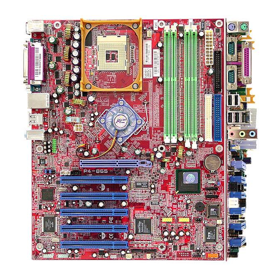
Overview P4-865PE MAX P4-865PE Pro P4-865P Ultra 1 - 3... -
Page 7: Main Features
865 Dynasty Mainboard Manual Main Features Celeron 1.4 G to 2.4 GHz and up* (865PE / 865P supports FSB 400) 2.0 to 2.8 GHz and up* (FSB 533) (865PE / 865P supports FSB 533) 3.06 GHz and up* (FSB 800) (only 865PE supports FSB 800) (*: not tested yet) Chipset North Bridge: Intel... - Page 8 Overview I/O Ports 2 IDE connectors - PIO, Bus Master, Ultra DMA 66/100 up to 4 devices 2 serial ports COM1 and COM2 1 parallel port PS/2 mouse and PS/2 keyboard 8 USB 1.1/2.0 ports RTL8100BL 10/100 Ethernet ® IEEE 1394 Ports (optional) Agere FW323 2 ports 1 bracket with cable...
-
Page 9: Fic Unique Innovation For Users (Novus) - Enhanced Mainboard Features And System Support
865 Dynasty Mainboard Manual FIC Unique Innovation for Users (NOVUS) - Enhanced Mainboard Features and System Support LogoGenie A user friendly GUI supporting Windows 95/98SE (not Windows 2000/ NT/ME/XP), LogoGenie allows you to customize, create or select a Logo which will be displayed when the system is booting. -
Page 10: Chapter 2 Installation Procedures
Chapter 2 Installation Procedures Installation Procedures The mainboard has several user-adjustable jumpers on the board that allow you to configure your system to suit your requirements. This chapter contains information on the various jumper settings on your mainboard. To set up your computer, you must complete the following steps: Step 1 - Set system jumpers Step 2 -... -
Page 11: Set System Jumpers
865 Dynasty Mainboard Manual 1). Set System Jumpers Clear CMOS The CMOS RAM is powered by the onboard button cell battery. To clear the RTC data: (1) Turn off your computer; (2) open the system case, disconnect the ATX power cable; (3) place the jumper cap onto the pinpair 2-3 at least 6 seconds to enable CMOS clearance;... -
Page 12: Install Memory Modules
Installation Procedures 2). Install Memory Modules 1. Locate DDR DIMM sockets on the mainboard. 2. Install DDR DIMM straight down into the socket 1 using both hands, then socket 2, and so forth. 3. The clip on both ends of the socket will close up to hold the DDR DIMM in place when the DDR DIMM reaches the socket bottom. -
Page 13: Install The Cpu
865 Dynasty Mainboard Manual 3). Install the CPU The mainboard has built-in Switching Voltage Regulator to support CPU Vcore autodetection. That is, It has the ability to detect and recognize the CPU volt- age, clock, ratio and enables users to set up the CPU frequency from the BIOS Setup Screen. -
Page 14: Connect Atx Power
Installation Procedures Affix the CPU by pressing the lever downward and locking it beside the socket. 3. Place the fan with heatsink on the CPU top and press down two plastic clips to hook up with the holes on the retention module on two sides. -
Page 15: Install Expansion Cards
865 Dynasty Mainboard Manual NOTE: Users The CPU installing procedures should be: 1. Insert the CPU (with its fansink and retention module) on the socket. 2. Connect the 4-pin plug of the power supply 3. Connect the 20-pin plug of the power supply. To remove the processor, please do it in reverse order. - Page 16 Installation Procedures 1. Select an available expansion slot. 2. Remove the corresponding slot cover from the computer chassis. Un- screw the mounting screw that secures the slot cover and pull the slot cover out from the computer chassis. Keep the slot cover mounting screw nearby. 3.
-
Page 17: Connect Devices
865 Dynasty Mainboard Manual 5). Connect Devices Floppy Diskette Drive Connector This connector provides the connection with your floppy disk drive. Insert the floppy ribbon cable (below) onto the floppy connector. The colored stripe (indicated by the arrow head, right) of the ribbon cable must be the same side with the Pin 1. -
Page 18: Fan Connectors
Installation Procedures Fan Connectors The two connectors, CPU_FAN, SYS_FAN are linked to the CPU fan, case fan, respectively. CHIP_FAN can be used with North Bridge chip fan. Power Connectors The 20-pin male block connector is connected to the ATX power supply. The 4-pin male block connector is for the ATX_12V power use. -
Page 19: Front Panel Block, Power Led, Ir, And Speaker Connector
865 Dynasty Mainboard Manual Front Panel Block, Power LED, IR, and Speaker Connector This block connector includes the connectors for linking with Power LED (3- pin), HDD LED, power button, power/sleep/message waiting button, reset buttonon the front panel of the system case. Please identify polarities of plug wires for the case speaker and LEDs. -
Page 20: Serial Ata Connectors
Installation Procedures (4) Power Button is connected with power button. Push this switch allows the system to be turned on and off rather than using the power supply button. IR is a pinheader that is used for linking with your ID device to allow transmis- sion of data to another system that also supports the IR feature. -
Page 21: Cd Audio-In Connector
865 Dynasty Mainboard Manual CD Audio-In Connectors The connectors, CD_IN and AUX_IN, are for CD-ROM drive audio analog input use. 1394 Connectors (optional) The 2 optional 1394 pinheaders on the board provides you with two connec- tions with the peripherals which own 1394 connectors by an optional bracket with cable (see the figure below). -
Page 22: Ps/2 Keyboard And Mouse Connector
Installation Procedures PS/2 Keyboard and Mouse Connector These two 6-pin female (PS/2 keyboard is purple color and PS/2 mouse is green color) connectors are used for your PS/2 keyboard and PS/2 mouse. RJ45 LAN Connector The LAN (RJ45 port) jack is used for the LAN cable plug. 2 - 1 3... -
Page 23: Serial Port Connectors
865 Dynasty Mainboard Manual Serial Port Connectors COM1/2 (9-pin D-sub male connector with teal color) allow you to connect with your devices that use serial ports, such as a serial mouse or an external modem. Printer Connector This 25-pin D-Sub female burgundy-colored connector is attached to your printer. -
Page 24: Audio I/O Jacks
Installation Procedures Audio I/O Jacks LINE_OUT (lime) can be connected to headphones or preferably powered speakers. LINE_IN (light blue) allows tape players or other audio sources to be recorded by your computer or played through the LINE_OUT. MIC_IN (pink) allows microphones to be connected for audio input. Front Audio Connector The mainboard has a front panel audio F_AUDIO connector... -
Page 25: Audio Channel Feature
865 Dynasty Mainboard Manual 5.1 Audio Channel Feature The 5_1_AUDIO sound feature are offered via the pinheaders with an op- tional A73 bracket with ribbon cable. The pinheaders pin assignments are shown below left. When use the daughter board, plug in the LINE_OUT jack for the front speaker audio output (right and left). -
Page 26: Universal Serial Bus Connectors
Installation Procedures Universal Serial Bus Connectors The mainbaord have eight USB ports; four USB black jacks that integrated on the edge of the board, the other four USB ports on the board. They allows uses to attach with USB devices either from rear or front panels. The USB cabe that comes with your mainboard is used to connecting between the USB pinheaders and rear panel. - Page 27 865 Dynasty Mainboard Manual This Page Left Blank for Note 2 - 1 8...
-
Page 28: Chapter 3 Bios Setup
Chapter 3 BIOS Setup BIOS Setup The mainboard comes with the chip that Award BIOS that contains the ROM Setup information of your system. (This chip serves as an interface between the processor and the rest of the mainboard components.) This section ex- plains the information contained in the Setup program and tells you how to modify the settings according to your system configuration. -
Page 29: Standard Cmos Setup
865 Dynasty Mainboard Manual Standard CMOS Setup The Standard CMOS Setup screen is displayed above. Each item may have one or more option settings. The system BIOS automatically detects memory size, thus no changes are necessary. Use the arrow keys to highlight the item and then use PgUp or PgDn keys to select the value you want in each item. - Page 30 BIOS Setup Hard Disks This field records the specifications for all non-SCSI hard drives installed in the system. The onboard PCI IDE connectors provide Primary and Sec- ondary channels for connecting up to four IDE hard disks or other IDE devices.
-
Page 31: Advanced Bios Features
865 Dynasty Mainboard Manual Advanced BIOS Features Virus Warning This feature starts the virus scan tool to detect if boot virus in boot sector of the first hard disk drive when booting up. The options are: Enabled, Disabled. CPU L1 & L2 Cache When enabled, improves the system performance. - Page 32 BIOS Setup F i r s t / S econd/Third Boot Device This feature allows user to select the boot device priority. The options are: Floppy, LS120, Hard Disk, CDROM, ZIP100, USB-FDD, USB-ZIP, USB- CDROM, USB-HDD, LAN, Disabled. Boot Other Device This feature allows user to select the boot device priority.
- Page 33 865 Dynasty Mainboard Manual Typematic Delay (Msec ) This feature is available only if the item, Typematic Rate Setting, is set at Enabled. Sets the delay time before a character is repeated. The options are: 250, 500, 750, 1000 millisecond. Security Option Allows to set the security level of the system.The options: Setup, System.
- Page 34 BIOS Setup NOTE: Please disable this BIOS feature about BIOS Guardian before you start to reflash BIOS. BIOS Guardian and Reflash BIOS BIOS Guardian by default is enabled, thus effectively acts as a fire- wall against viruses that can attack the BIOS while the system is running.
-
Page 35: Advanced Chipset Features
865 Dynasty Mainboard Manual Advanced Chipset Features DRAM Timing Selectable This feature allows user to select the way to set DRAM timing. The options are: Manual, By SPD. CAS Latency Time This feature allows user to select the CAS latency time, when any SDRAM DIMM installed. - Page 36 BIOS Setup System BIOS Cacheab l e Setting at Enabled will allow the caching of the BIOS ROM F0000H-FFFFFH, resulting in better system performance. It may cause system error when some programd try to access the memory area. The options are: Disabled, Enabled. Video BIOS Cacheab l e Setting at Enabled will allow the caching of the video BIOS ROM at C0000H- C7FFFH, resulting in better video performance.
-
Page 37: Integrated Peripherals
865 Dynasty Mainboard Manual Integrated Peripherals OnChip IDE Device IDE HDD Block Mode When enabled, the system executes read/write requests to hard disk in block mode. The options are: Enabled, Disabled. On-Chip Primary PCI IDE When enabled, it allows you to use the onboard primary PCI IDE. The options are: Enabled, Disabled. - Page 38 BIOS Setup IDE Secondary Master/Slave PIO Allows an automatic or a manual configuration of the PCI secondary IDE hard drive (master/slave) mode. The options are: Auto, Mode 0, Mode 1, Mode 2, Mode 3, Mode 4. UDMA IDE Secondary Master/Slave Allows an automatic configuration of the PCI secondary IDE hard drive (master/slave) mode if Ultra DMA is supported both on the motherboard and the hard disk.
- Page 39 865 Dynasty Mainboard Manual *** On-Chip Serial ATA Setting *** Onboard Seria l ATA This feature allows users to disable the optional onboard SATA chip. The options are: Enabled, Disabled. S ATA Mode (depends on the core chip ) This feature allows users to select SATA specifications that embeded func- tions in South Bridge.
-
Page 40: Power Management Setup
BIOS Setup UR2 Duplex Mode Allows you to select the IR modes. The options are: Full, Half. Onboard Parallel Port Allows you to select from a given set of parameters if the parallel port uses the onboard I/O controller. The options are: Disabled, 378/IRQ7, 278/IRQ5, 3BC/IRQ7. Parallel Port Mode Allows you to connect with an advanced printer via the port mode it supports. - Page 41 865 Dynasty Mainboard Manual ACPI Function This item allows you to disable the ACPI function. The options are: Enabled, Disabled. ACPI Suspend Type This item allows you to select suspend mode when the system in ACPI mode. The options are: S1 (POS), S3 (PTR), S1&S3. Run VGABIOS if S3 Resume This feature allows you to decide the way if VGA BIOS should be called when the system resumes from S3 state if the above feature is set at S3...
- Page 42 BIOS Setup Suspend Mode When disabled, the system will not enter Suspend mode. The specified time option defines the idle time the system takes before it enters Suspend mode. The options are: Disable, 1, 2, 4, 8, 10, 20, 30, 40 Min, 1 Hour. H D D Power Down The option lets the BIOS turn the HDD motor off when system is in Sus- pend mode.
-
Page 43: Reload Global Timer Events
865 Dynasty Mainboard Manual Date (of Month) Alarm This feature allows you to set the day of the alarm starts when the RTC Alarm Resume From Soft Off is set to be Enabled. The options are: 0, 1..31. Ti me (hh:mm:ss) Alarm If an ATX power supply is installed and when RTC Alarm Resume is En- abled, this feature allows you to set the time of the alarm starts when the RTC Alarm Resume From Soft Off is set to be Enabled. -
Page 44: Pnp/Pci Configurations
BIOS Setup PnP/PCI Configurations PNP OS Installed If your operating system is a Plug-and-Play one, such as Windows NT, Windows 95, select Yes. The options are: No, Yes. Reset Configuration Data Enabling it to reset the system Extended System Configuration Data (ESCD) when you exit Setup if you have installed a new add-on card and the system reconfiguration has caused such a serious conflict that the operat- ing system can not boot. -
Page 45: Pc Health Status
865 Dynasty Mainboard Manual INT Pin 1/2/3/4/5/6/7/8 Assignment This feature allows you to assign the PCI IRQ numbers for PCI slots. Selecting the default, Auto, allows the PCI controller to automatically allo- cate the IRQ numbers. The options are: Auto, 3, 4, 5, 7, 9, 10, 11, 12, 14, 15. PC Health Status Shutdown Temperature This feature helps to shutdown the system when the system temperature... -
Page 46: Frequency/Voltage Control
BIOS Setup Frequency/Voltage Control CPU Clock Ratio This item allows users to set the wanted CPU clock ratio. Auto Detect PCI Clk When enabled, BIOS will detect the PCI slot slot. If no any device in, BIOS will auto disable its clock. The options are: Enabled, Disabled. Spread Spectrum This feature allows users to select the range of spread spectrum. -
Page 47: Load Fail-Safe Defaults
865 Dynasty Mainboard Manual CPU Voltage Regulator This item allows you to set the CPU Vcore voltage. Options: 1.450V to 1.625 V in 0.025V increments. We recommend that you leave this at the default value (with * mark). A G P Voltage Regulator This item allows you to set the AGP slot voltage. -
Page 48: Save And Exit Setup
BIOS Setup Under the BIOS Feature Setup, if Setup is selected under the Security Option field and the Supervisor/User Password is enabled, you will be prompted password every time you try to enter the CMOS Setup Utility. If System is selected and the Supervisor/User Password is enabled, you will be requested to enter the Password every time when you reboot the system or enter the CMOS Setup utility. - Page 49 865 Dynasty Mainboard Manual This Page Left Blank for Note 3 - 2 2...
Need help?
Do you have a question about the P4-865PE MAX and is the answer not in the manual?
Questions and answers