Table of Contents
Advertisement
Quick Links
DRAFT COPY
© ELECTROLUX ZANUSSI S.p.A.
Corso Lino Zanussi,30
I - 33080 PORCIA /PN (ITALY)
Tel +39 0434 394850
Fax +39 0434 394096
TSE-P
Edition: 10.2000
TSE-P 10.00 FV
Publication No.
599 34 41-93
EN/SERVICE/FV
1/38
SERVICE MANUAL
COOKING
GAS OVEN
WITH
ELECTRONIC
CONTROL
EOG621B
EOG621W
599 34 41-93
Advertisement
Table of Contents

Related Manuals for Electrolux EOG621B


Summary of Contents for Electrolux EOG621B
- Page 1 SERVICE MANUAL COOKING DRAFT COPY GAS OVEN WITH ELECTRONIC CONTROL © ELECTROLUX ZANUSSI S.p.A. Publication No. Corso Lino Zanussi,30 EOG621B I - 33080 PORCIA /PN (ITALY) 599 34 41-93 Tel +39 0434 394850 EOG621W Fax +39 0434 394096 EN/SERVICE/FV TSE-P Edition: 10.2000...
- Page 2 GENERAL WARNINGS For proper functioning and for safety purposes it is necessary that this type of oven be installed properly (see installation in the Instruction booklet extract, page 19) by competent and qualified installers, according to local legislation. It is extremely important not to obstruct the air circulation necessary for correct burner combustion. This oven can function with several types of gas: before installing the oven it is necessary to check that the burner injector is suitable for the type of gas (see table on page 23) otherwise it is necessary to replace the burner nozzle (see adaptation of the burner to...
-
Page 3: Table Of Contents
INDEX INTRODUCTION ------------------------------------------------------------------------------------------ page TECHNICAL FEATURES ------------------------------------------------------------------------------- page CONTROL PANEL ---------------------------------------------------------------------------------------- page 24 HOUR CLOCK AND TIMER------------------------------------------------------------------------ page GENERAL DESCRIPTION------------------------------------------------------------------------------ page FUNCTIONAL DESCRIPTION------------------------------------------------------------------------- page SPARK PLUG / FLAME DETECTOR GAPS ------------------------------------------------------- page GAS CIRCUIT ---------------------------------------------------------------------------------------------- page GAS CIRCUIT DIAGRAM ------------------------------------------------------------------------------- page SOLENOID VALVE --------------------------------------------------------------------------------------- page CONTROL CIRCUIT AND CONTROL UNIT ------------------------------------------------------- page GAS BURNER CONTROL CIRCUIT ----------------------------------------------------------------- page... -
Page 4: Introduction
INTRODUCTION Each oven is thoroughly checked before leaving the factory in order to ensure correct operation and compliance with the laws in force at the time of construction. The safety of the oven depends also on proper installation and on the fact that the user understands how to use the oven and keep it efficient. -
Page 5: Control Panel
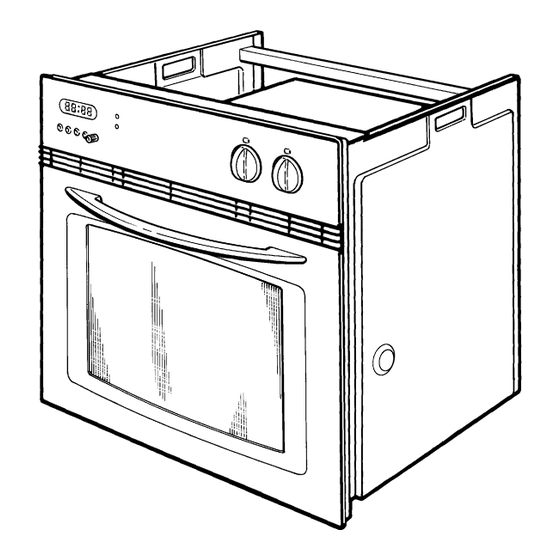
CONTROL PANEL Fig. 1 1 - Thermostat control knob 4 - Thermostat control Light 2 - Gas stop control Light (LED) 5 - Main “ON” Light 3 - Oven function control knob 6 - Electronic programmer THERMOSTAT Fig. 2 FUNCTION SELECTOR Oven Light - The oven light will be on without any cooking function. -
Page 6: 24 Hour Clock And Timer
24 HOUR CLOCK AND TIMER Minute minder Cooking duration End of cooking time Manual function Saucepan symbol – This will be displayed when a Program is in operation. Auto symbol – This will be displayed when the oven has been programmed for automatic operation. - Page 7 MANUAL OPERATION Press button to set the oven to manual operation. TO SET THE TIMER TO SWITCH OFF ONLY This is useful if you want to begin cooking immediately but have the oven switch off automatically. 1 . Set the oven function control knob and the thermostat control knob to the required settings.
-
Page 8: General Description
GENERAL DESCRIPTION The two models - EOG621B and EOG621W - differ only as regards their styling (colours). Both models are designed for the following types of cooking: - Normal gas cooking. - Electric grill cooking. - Electric grill plus spit cooking. -
Page 9: Spark Plug / Flame Detector Gaps
SPARK PLUG / FLAME DETECTOR GAPS In order to assure that the system functions correctly, the ignition spark plug and flame detector must be correctly positioned. The ignition spark plug/flame detector is secured by a rigid bracket in a precisely-determined position. If the spark plug is bent or incorrectly positioned, this will alter the gap and may result in incorrect operation. -
Page 10: Gas Circuit Diagram
GAS CIRCUIT DIAGRAM Fig. 11 TSE-P 10.00 FV 10/38 599 34 41-93... -
Page 11: Solenoid Valve
SOLENOID VALVE The solenoid valve which controls the flow of gas to the burner is powered by direct current and actioned by the electronic control unit. If the gas supply should be interrupted (the gas solenoid valve does not open), check that the electronic control unit supplies the correct voltage to the solenoid valve. -
Page 12: Control Circuit And Control Unit
CONTROL CIRCUIT AND CONTROL UNIT The control circuit for the burner consists of an electronic control unit which is actioned by the oven thermostat and the function selector knob. The electronic control unit controls the flow of gas by means of the solenoid valve positioned at the gas intake. -
Page 13: Simplified Diagram Of Control Unit Connections
SIMPLIFIED DIAGRAM OF CONTROL UNIT CONNECTIONS IGNITION SPARK PLUG/FLAME DETECTOR ELECTRONIC CONTROL UNIT GAS CONTROL SOLENOID VALVE “GAS BLOCK” LED SUPPRESSOR SPARK GENERATOR TERMINAL BLOCK ENERGY REGULATOR TSE-P 10.00 FV 13/38 599 34 41-93... -
Page 14: Safety Thermostat
SAFETY THERMOSTAT The entire electrical circuit of the oven is protected against overheating by a normally-closed ceramic thermostat (see fig. 15) which opens at a temperature of 270°C in the centre of the oven. The main cause for intervention of the safety thermostat is generally a malfunction of the tangential fan; however, the thermostat may also intervene if the appliance is not correctly built in. -
Page 15: Electronic Control Unit Test Circuit
ELECTRONIC CONTROL UNIT TEST CIRCUIT In case of doubt concerning the operation of the electronic control unit, use the test circuit shown below (figg. 17 and 18). This circuit should feature a switch with a built-in neon pilot lamp, a series of 220V neon pilot lamps indicating “appliance ON”, “gas valve open”... - Page 16 Fig. 18 1 - TEST CIRCUIT 2 - MAIN SWITCH 3 - IONIZATION SWITCH LED1 4 - “GAS BLOCK” PILOT LAMP 5 - “GAS VALVE OPEN” PILOT LAMP 6 - “IGNITION” PILOT LAMP 7 - “GAS TO ENERGY REGULATOR” PILOT LAMP 8 - ELECTRONIC CONTROL UNIT BEING TESTED 9 - 10-PIN CONNECTOR The circuit illustrated above can be used to check that the electronic control unit operates in the correct...
-
Page 17: Functional Diagram Of The Test Circuit
FUNCTIONAL DIAGRAM OF THE TEST CIRCUIT Fig. 19 Fig. 20 TIMES T1) The control unit performs an internal check T2) The burner must switch on within this period T3) Normal operation of the burner Moment at which the burner lights Moment at which the control unit blockage occurs TSE-P 10.00 FV 17/38... -
Page 18: Gas Section Troubleshooting
GAS SECTION TROUBLESHOOTING ACTION WHAT HAPPENS? CHECK..Turn the The pilot lamp indicating - the power supply function selector that the thermostat is in - the safety Klixon knob on the gas operation does not light. - closure of the programmer contacts - closure of the function selector contacts oven to (P1-1 and P2-4) -
Page 19: Instructions For The Installer
INSTRUCTIONS FOR THE INSTALLER TECHNICAL DATA OVEN Model Number : EOG 621 Grill Element 1,830 W Oven burner 2,700 W (Natural gas) APPLIANCE GAS SUPPLY: Natural Gas G20 20 mbar 2,500 W (LPG) APPLIANCE CATEGORY: II2H3+ Oven light 25 W Cooling fan 25 W CABINET DIMENSIONS... -
Page 20: Important Safety Requirements
IMPORTANT SAFETY REQUIREMENTS This appliance must be installed in accordance with the Gas Safety (Installation and Use) Regulations (current edition) and the I.E.E. Wiring Regulations. Detailed recommendations are contained in the following British Standard Codes of practice – B.S.6172, B.S.5440: Part 2 and B.S.6891: Current Editions. PROVISION FOR VENTILATION This appliance is not connected to a combustion products evacuation device. -
Page 21: Building In
BUILDING IN LOCATION OF APPLIANCE The appliance may be located in a kichen, a kitchen/diner or bedsitting room but not in a bathroom, shower room or bedroom. It is essential that there is a minimum clearance of 3 mm between the top surface of the appliance and the inside top of the cabinet. -
Page 22: Electrical Connection
SECURING THE OVEN TO THE CABINET 1 . Fit the oven into the cabinet recess, 2 . Open the oven door 3 . Secure the oven to the kitchen cabinet with four wood screws, which fit the holes provided in the oven frame. - Page 23 ELECTRICAL CONNECTION FITTING THE APPLIANCE AND CABINET The gas supply connection ramp is positioned in the front upper side of the oven, behind the control panel. To carry out the gas connection, partially insert the oven in the recess (about 30cm.) and operate on the connection ramp from the top.
-
Page 24: Conversion From Natural To Lpg Gas
CONVERSION FROM NATURAL TO LPG GAS IMPORTANT Replacement/conversion of the gas hob shoud only be undertaken by a CORGI- registered engineer. It is important to note that this model is designed for use with butane or propane gas providing the correct injectors are fitted. -
Page 25: Accessibility
ACCESSIBILITY Warning: Before gaining access to the internal parts, close the gas delivery and disconnect the electrical power supply. REMOVING THE OVEN Access to some of the components is possible by removing the oven from the cabinet only partially. With the partial removal of the oven it is possible to again access to the components of the panel and the electronic control unit;... -
Page 26: Removal Of The Control Panel
DISCONNECTION OF THE GAS SUPPLY To disconnect the gas supply proceed as follows: - remove the oven from the cabinet - unscrew the fixing screw of the gas connection pipe to the gas pipe coupling (see Fig. 33). Fig. 33 1 - OVEN GAS INLET PIPE 2 - GAS CONNECTION NUT 3 - GAS SUPPLY INLET PIPE... -
Page 27: Disassembly Of The Control Panel
DISASSEMBLY OF THE CONTROL PANEL To disassemble the control panel, proceed as follows:: - Remove the fixing screws on the front frame (see Fig. 35) - Remove the knobs. - Remove the fixing screws from the lower section of the front panel Fig. -
Page 28: Disassembly Of The Rear Panel
Fig. 37 1 - FUNCTION SELECTOR 2 - WIRING CONNECTOR 3 - ELECTRONIC CONTROL UNIT 4 - FIXING SCREWS OF ELECTRONIC CONTROL UNIT DISASSEMBLY OF THE REAR PANEL To disassemble the rear panel: - Remove the oven from the cabinet - Disconnect the gas connection. - Page 29 Fig. 38 1 - GAS SOLENOID VALVE 2 - GAS INLET PIPE 3 - OVEN LAMPHOLDER 4 - SAFETY THERMOSTAT 5 - GRILL HEATER ELECTRICAL CONNECTORS 6 - PROTECTION THERMOSTAT 7 - TANGENTIAL COOLING FAN 8 - TURNSPIT MOTOR 9 - IGNITION TRANSFORMER 10 - SUPPRESSOR 11 - ELECTRICAL CONNECTION TERMINAL BOARD...
-
Page 30: Disassembly Of The Top Panel
DISASSEMBLY OF THE TOP PANEL To disassemble the top panel: - Remove the oven from the cabinet. - Disconnect the gas connection. - Unscrew the fixing screws of the panel (see Fig. 40). Fig. 40 1 - TOP PANEL 2 - GAS SOLENOID VALVE 3 - GAS INLET PIPE 4 - PROTECTION THERMOSTAT (FAN CONTROL) -
Page 31: Disassembly Of The Tangential Cooling Fan
Fig. 42 1 - TANGENTIAL COOLING FAN 2 - OVEN LAMPHOLDER DISASSEMBLY OF THE TANGENTIAL COOLING FAN To disassemble the tangential cooling fan it is necesssary to: - Disassemble the rear panel. - Disassemble the top panel. - Disconnect the connection wires, marking the various positions. - Unscrew the fixing screws of the fan placed in the internal section (see Fig. -
Page 32: Disassembly Of The Gas Solenoid Valve
DISASSEMBLY OF GAS SOLENOID VALVE To disassemble the gas control solenoid valve it is necessary to: - Disconnect the gas connection. - Disassemble the rear panel. - Disconnect the connection wires, marking the various positions. - Unscrew the nuts which secure the gas inlet and outlet to the solenoid valve - Remove the screws from the solenoid valve assembly and detach the solenoid valve from the... -
Page 33: Disassembly Of The Safety Thermostat And Protection Thermostat
DISASSEMBLY OF THE SAFETY THERMOSTAT AND THE PROTECTION THERMOSTAT To gain access to the safety thermostat and the protection thermostat it is sufficient to: - Disassemble the rear panel. - Unscrew the nut which secures the thermostat, located inside the oven compartment. - Disconnect the connection wires, marking the various positions. - Page 34 ACCESS TO THE BURNER AND THE SPARK PLUG/FLAME DETECTOR To access the oven burner and the spark plug/flame detector, proceed as follows: Remove the bottom panel from the interior of the oven. Remove the screws which secure the burner in position (see fig. 50). Remove the burner from its seat.
- Page 35 Fig. 52 1 - OVEN BURNER Fig. 53 1 - SPARK PLUG/FLAME DETECTOR 2 - OVEN BURNER 3 - SPARK PLUG SUPPORT TSE-P 10.00 FV 35/38 599 34 41-93...
-
Page 36: Basic Diagram
BASIC DIAGRAM TSE-P 10.00 FV 36/38 599 34 41-93... -
Page 37: Wiring Diagram
WIRING DIAGRAM TSE-P 10.00 FV 37/38 599 34 41-93... -
Page 38: Wiring Diagram Legend
WIRING DIAGRAM LEGEND 1 Ignitor 59 Logic p.c.b. 2 Ignitor supply 60 Water level probe 3 Hob supply 61 Water level indicator 4 Steak cookplate 62 Residual heat pilot lamp 5 Boiler 63 Grill pilot lamp 6 Electrical connection 64 Mains on pilot lamp 7 Rotary switch 65 Microwave pilot lamp 8 Hot plate rotary switch...
Need help?
Do you have a question about the EOG621B and is the answer not in the manual?
Questions and answers