
Subscribe to Our Youtube Channel
Related Manuals for Vista SmartDisc 10IP


Summary of Contents for Vista SmartDisc 10IP
- Page 1 Vista SmartDisc 10IP Digital Video Recorder/Transmitter VLS-10DR/IP-Series Installation & Instruction Manual 1.84...
- Page 2 SmartDisc 10IP Device Manual Version 1.84 (English)
- Page 4 Vista SmartDisc 10IP Device Manual Vista SmartDisc 10IP...
-
Page 5: Limited Warranty
This manual may nevertheless include technical inexactitudes and misprints. Due to the speed of technological development, we reserve the right to include technical alterations and developments without special advance notice. Vista therefore does not make any warranty with respect to this manual or the continuing validity of these texts. Furthermore, Vista is not liable for any loss or misuse of information resulting from the use of this manual. In particular, Vista is not liable for any damages such as ... -
Page 6: Table Of Contents
..........35 Description of "Site archive" features ......39 5.1 Storage concept ................... 39 Advantages of the multi-track recording process ........39 Camera tracks ................... 39 Recording modes ..................41 Continuous recording ................42 Event triggered recording ................45 5.2 Log File ....................47 Log file command overview ............... 48 Web Server ..................53 Vista SmartDisc 10IP... - Page 7 SmartDisc 10IP Technical Data ........... 57 7.1 Technical data for the HYBRID Card 4 ........... 59 Factory settings ................61 General settings Part 1/3 ................61 Connections ....................61 Camera-specific settings ................62 Alarm ......................62 Site archive ....................63 General settings Part 2/3 ................64 EMA (IDS = intrusion detection system) ............. 64 Extras ......................64 General settings Part 3/3 ................64 Interface specifications ................66 Troubleshooting ................
-
Page 8: How To Use This Manual
19" Mount Kit please refer to the information in the installation instructions for the module or the installation kit as well. Conventions Highlighting Text referring to product names, dialog windows, buttons or illustrations is printed in bold face (e.g. SmartDisc 10IP, HYBRID Card 4, OK, Connect). Comments and special instructions are placed in grey boxes. Additional exclamation marks (see left) indicate information of special importance. Orientation Key words and program symbols on the left will help you find your way around and make it easier to get back to sections already read. - Page 9 1 How to use this manual Vista SmartDisc 10IP...
-
Page 10: Introduction
Continuous recording on integrated removable hard disk with adaptive ■ multi track management and motion (only for analogue video signals) or contact controlled recording controlled by timer with calendar feature Multi-criteria evaluation of hard disk recordings by IP and/or dial-up ■ connection, and in offline mode with PC adapter SmartDisc IP Caddy (USB) Live image replication and stored image playback parallel to background ■ recording Vista SmartDisc 10IP... - Page 11 Video multiplexer each with 4 video inputs with the HYBRID Card 4 ■ expansion card (maximum 2 cards per device) SmartDisc 10IP All options for the SmartDisc 10IP can be conveniently integrated into your options SmartDisc 10IP unit or combined with your SmartDisc 10IP. All modules and external adapters are ready for plug-in. Refer to chapter "System description" for more information (see “Accessories” on page 11). Vista SmartDisc 10IP...
-
Page 12: System Description
Please keep the original packing, if convenient. This packing will facilitate return of the product. 3.2 Accessories Hard disks and Frame mounted removable hard disk with up to 2000 GB capacity for the ■ accessories SmartDisc IP series SmartDisc IP Caddy (USB): External USB adapter for device-independent ■ evaluation of SmartDisc 10IP removable hard disks It is essential that you observe the information provided in chapter "Removable Hard Disk"(see “Removable hard disk” on page 29). Vista SmartDisc 10IP... -
Page 13: Warranty
Warranty will be voided in this case. Please maintain the ambient conditions described below when using your SmartDisc 10IP device. General safety information Make sure to carefully read and understand this manual before operating ■ the device. Do not expose the device to strong vibration or shock. ■ Avoid humidity or dust, extreme temperature fluctuations, or strong ■ magnetic fields. Vista SmartDisc 10IP... -
Page 14: Electrical Safety
SmartDisc 10IP, the power supply unit, cables, or sockets. Never touch these with wet hands. Disconnect the device from the power supply by pulling at the plug, not at ■ the cable. Never pull at the cable. If water or any other liquid enters the device, immediately disconnect the ■ power supply. Have the device checked by customer service. The device contains no components that can be adjusted or repaired by ■ the user. The device housing must never be opened ever. Only authorised staff may open the housing for installing HYBRID Card 4, ■ PSTN Cards or ISDN Cards. The instructions in the included manuals must be observed. Vista SmartDisc 10IP... -
Page 15: System Environment
Only one of the following software packets, developed by Vista especially for CCTV applications, is required for the PC based receiver/evaluation unit. SmartControl (included in SmartDisc 10IP delivery) ■ software for operation, alarm verification, and configuration for single workstations with up to 6000 transmitters SmartDisc 10IP, ... -
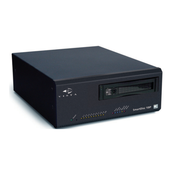
Page 16: Controls, Indicators, And Ports
An illuminated LED in combination with illuminated LED Error (4) indicates LEDs - yellow video signal failure of the respective video input. Tip: Deactivate unused camera inputs using device settings. An LED chaser light from left to right indicates hard disk initialisation. Error An illuminated red LED indicates malfunctions, such as system errors or video LED - red signal failure. Viewing the SmartDisc 10IP logfile resets the indicator. You can configure the onboard SmartDisc 10IP relays so that the error will also activate a relay. Online An illuminated LED indicates an online connection. LED - blue Vista SmartDisc 10IP... - Page 17 LED - yellow, not image write operations and system access, like transmission of date and time labelled data. Removable hard disk The continuously-lit LED indicates that the hard disk chassis is being supplied LED - green, not with power. labelled Keyswitch Keyswitch for unlocking/unlocking the removable hard disk. It is essential that you observe the information provided in chapter "Removable hard disk (see “Removable hard disk” on page 29). Removable hard disk Removable hard disk for digital video recording. It is essential that you observe the information provided in chapter "Removable hard disk" (see “Removable hard disk” on page 29). Vista SmartDisc 10IP...
-
Page 18: Rear View And Description
Card for a B channel or the optional PSTN Card to connect to an analogue data line. Modem/Nullmodem 9 pin sub D plug: Serial interface (RS-232) for direct connection of external modules for MODEM, ISDN-TA, GSM, or of PC with Vista null modem cable. Note: Pin assignment is detailed in section "Pin assignment and functionality" (see “Modem/Nullmodem” on page 23) Vista SmartDisc 10IP... - Page 19 The interface is prepared for POS functionality and serial remote control of certain SmartDisc 10IP features. Note: Pin assignment is detailed in section "Pin assignment and functionality"(see “Terminal Transp. data/Control interface” on page 25) Jack socket: Direct connection of an Electret or of an electrostatic microphone (see “Audio connections SmartDisc 10IP” on page 26). Line in Jack socket: Direct connection of an audio source with line level output (see “Audio connections SmartDisc 10IP” on page 26). Line out Jack socket: Direct connection of an audio source with line level input (see “Audio connections SmartDisc 10IP” on page 26). Vista SmartDisc 10IP...
-
Page 20: Pin Assignment And Functionality
Note: The operation of this input is independent of the status of the arm/disarm enable input "Al a/d" 11 Control in 1-5 Control Camera control inputs for external contact triggered recording and/or to input selective dial-up to a SmartControl receiver unit for video inputs 1 to 5. These control inputs can be used for event recording as well as for event optimised permanent long-term recording. ⊥ Ground Common ground for all inputs of type "control input" ⊥ Ground Common ground for all inputs of type "control input" 12V DC + Power, + Supply voltage is nominal 12V DC (Voltage input from 8-16 V DC). Only connect the device to your local power supply system using the ⊥ 12V DC Power, provided power supply unit with the prepared connection cable. Only ground use the power supply cable matching your grid (Euro/UK). Vista SmartDisc 10IP... - Page 21 ■ Switching to at least one SmartControl receiver unit with active R2 [normally open] Relay online connection ■ Error relay R2 [normally closed] Relay Aux in2 Control Auxiliary input 2: Reserved input ⊥ Ground Common ground for all inputs of type "control input" 28 Control in 6-10 Control Camera control inputs for external contact triggered recording and/or to input selective dial-up to a SmartControl receiver unit for video inputs 6 to 10. These control inputs can be used for event recording as well as for event optimised continuous recording. Speaker + Audio You can connect a 1 W/8 Ohm loudspeaker on this output to listen to the audio on the property being monitored. The output is protected against overload, but not against shorts. Using Speaker – Audio a speaker with matching maximum output is recommended. Pin assignment terminal block Vista SmartDisc 10IP...
-
Page 22: Control Inputs, Error Relay, Sabotage Protection
“Normally opened” Circuit Circuit external internal external internal (5V) (5V) 820 Ohm 820 Ohm 6,1V 6,1V Error relay The device configuration allows designation of integrated relays as error relays in order to report certain operating states or malfunctions using dry contacts. The status of the error relay then always corresponds to the status of the Error LED on the front of SmartDisc 10IP Error if Error LED on, then error relay energised ■ No error, if Error LED off, then error relay de-energised ■ Vista SmartDisc 10IP... - Page 23 For a detailed list of error messages that can trigger the error relay, refer to chapter "Log file". Viewing the Log File automatically causes reset of the error message; the error relay is de-ernergised and Error LED goes out. Refer to the manual of the respective SmartControl software for more information on log file configuration and evaluation. Sabotage protection The error relay is pulled in idle - no error. Therefore the error relay can be used as sabotage detector, as it automatically falls off in the event of power failure (e.g. caused by cut power lines). Depending on the error relay wiring, an interruption of the relay line itself can be reported as well. There is a theoretical possibility that sabotage protection will not work if error relay switching is not consistent with the operating mode. Vista SmartDisc 10IP...
-
Page 24: Ethernet And Isdn Interfaces
Connecting to the telephone line when using the PSTN Card: Connection to the telephone line Pin Layout RJ45 Pin Signal Meaning Telephone signal Telephone signal Modem/Nullmodem Connecting external dial-up devices for remote connections to SmartControl units. Use the connecting cable provided with the dial- up adapter. Serial direct connection to a SmartControl unit with the optional Vista null modem cable. This connection mode is recommended for commissioning and service. Vista SmartDisc 10IP... - Page 25 Input Data Carrier Detect Input Receive Data Output Transmit Data Output Data Terminal Ready Ground Ground Input Data Send Ready Output Ready to Send Input Clear to Send Direct connection SmartControl software and SmartDisc 10IP automatically detect a with null modem connection between interfaces connected by the optional Vista null modem cable cable. They will attempt to establish a direct connection. To this end, a special cable plug code is queried when starting SmartControl software. Ensure to plug in the null modem cable before starting the device and the SmartControl software. Vista SmartDisc 10IP...
-
Page 26: Terminal Transp. Data/Control Interface
Configuration A (typical): 9 pin Sub-D - 9 pin Sub-D ■ Configuration B (atypical): 9 pin Sub-D - 25 pin Sub-D ■ As a rule, no cables need to be prepared. The cable provided with the dial- up device can be used for remote connections, the optional Vista null modem cable can be used for direct connections. Terminal Transp. data/Control interface 1. Transparent transmission of serial data between SmartDisc 10IP and SmartControl receiver unit. Data will be transmitted unaltered between the devices, even when using different bit rates for the ... -
Page 27: Audio Connections Smartdisc 10Ip
RS-232 interface Sub-D socket Type Function Code designation Output Transmit Data Input Receive Data Ground Ground Input Clear to Send Output Ready to Send Audio connections SmartDisc 10IP With SmartDisc 10IP devices, you always should use a 3.5 mm stereo jack for the audio connections Mic, Line in and Line out. Please observe the fol- lowing table for connection details. Connections stereo jack Input Pin 1 Pin 2 Pin 3 signal no connection... -
Page 28: Hybrid Card 4
SmartControl PRO software (minimum requirement: Version 3.86 in each case). Installed The graphic shows the recorder settings for a SmartDisc 10IP with an HYBRID Card 4 installed HYBRID Card 4. For the individual camera channels for the expansion card, the DSP information is displayed (e.g. BF547 / 01.02 / 00.02 01.00). Vista SmartDisc 10IP... -
Page 29: Esata Interface
3 System description The Enabled option allows you to take the relevant analogue video inputs into operation. Please note that an enabled analogue video input always has priority over an IP camera that has been configured for the same channel. eSATA interface The eSATA interface is designed for future development. Vista SmartDisc 10IP... -
Page 30: Storage Media
SmartDisc 10IP Hard disk To avoid transport damage, SmartDisc 10IP and removable hard disks are commissioning delivered separately. Refer to additional information on commissioning on the label with the internal serial number of Vista attached to the housing cover of the removable hard disk (see illustration below). This information is important for: Unique serial number allocation for service ■ Comparing serial numbers in applications with several ... - Page 31 / Download. Furthermore, you can transfer backed-up device settings to other SmartDisc 10IP devices. These other devices must have the same number of camera inputs and the same firmware version. Offline evaluation To evaluate SmartDisc 10IP recordings offline, i.e. independent from a SmartDisc 10IP unit, the evaluation PC requires preparation for receiving the removable hard disk. Use the external SmartDisc IP Caddy (USB) for direct connection by USB interface to the evaluation PC (desktop, notebook). The advantages of option USB are: fast and convenient commissioning ■ Vista SmartDisc 10IP...
- Page 32 LED Error or the error relay, and clock error display will be deactivated. This operating mode is available only if the device does not detect any hard disk (and therefore no removable hard disk in the removable frame). If SmartDisc 10IP detects a functional hard disk after start up with option Use without hard disk drive activated, the option will be ignored and the removable hard disk will be used. If the hard disk fails during operation, all hard disk related errors will be read out until the next reset. Vista SmartDisc 10IP...
-
Page 33: Device Reset
You need a 9 pin Sub-D plug with pin 2 connected to pin 3, and pin 7 ■ connected to pin 8. Plug this reset plug into the interface labelled "Transp. data/Control ■ interface" (see “Pin assignment and functionality” on page 19). Switch the SmartDisc 10IP unit on and wait until LED Power on the front ■ starts flashing. Remove the reset plug. ■ Your SmartDisc 10IP unit will be ready again as soon as device reset and ■ re-initialisation have been completed. Pin assignment of Transp. data/Control interface RS-232 interface Connector end view / 9 pin Sub-D socket Vista SmartDisc 10IP... -
Page 34: Commissioning
(see Receiver options/Extras/ USB). If you use a network cable: Open SmartControl software in offline ■ mode. Go to menu item Settings, menu item Port A, menu item Mode. Activate option TCP/IP. In addition, include your SmartDisc 10IP unit as new transmitter in the transmitter list, including the SmartDisc 10IP TCP/IP address. The factory settings Vista SmartDisc 10IP... - Page 35 4 Commissioning are: IP address =192.168.31.95; subnet mask =255.255.255.0; Activate the transmitter list with option Dial. Refer to the SmartControl software online manual for all further steps concerning commissioning and configuration. Vista SmartDisc 10IP...
-
Page 36: General Configuration Information
The number of events will be reduced by the frame storage device if ■ storage space allocated to any camera for any single event is less than 3 MB. The device gives highest priority to image recording triggered by input ■ state change, i.e. when recording via Edge + or Edge – is enabled. If the device has detected a change on a control input, it will interrupt recording triggered by a different status, by status change or (on analogue cameras) Vista SmartDisc 10IP... - Page 37 SmartControl stations affects SmartDisc 10IP performance. You can enter up to four Telephone numbers / IP addresses that will be ■ processed in the event of an alarm, according to configurable criteria. Field one has top priority. SmartDisc 10IP always dials these numbers consecutively until one of the receivers is contacted. The number of Vista SmartDisc 10IP...
- Page 38 3 seconds. Recording is resumed after error elimination. For non recording video cameras failure will be reported after 60 seconds. If you require additional features, please refer to the additional configuration CAMTEL.INI CAMCTRL.INI options in files or . Refer to the respective SmartControl SmartControl PRO information in the or software online manuals. Vista SmartDisc 10IP...
- Page 39 4 Commissioning Vista SmartDisc 10IP...
-
Page 40: Description Of "Site Archive" Features
Refer to descriptions of the setup dialogs in the SmartControl and SmartControl PRO software online manuals. 5.1 Storage concept SmartDisc 10IP allows digital recording of up to 10 camera signals. The multi-track recording process developed by Vista allows hard disk storage capacity to be adjusted individually for each camera. Advantages of the multi-track recording process The hard disk storage capacity is used in the ideal manner. ■ The recording period is specified for each individual camera track. ■... - Page 41 Delete all pictures If special requirements for the period of image storage must be complied older than [] days with, for example for reasons of data privacy, a maximum age can be specified for archive images per camera track. Any older images will then be deleted automatically. Vista SmartDisc 10IP...
-
Page 42: Recording Modes
The illustration above shows flexible storage capacity allocation for space allocation permanent recording and event triggered recording. On the basis of set recording parameters, SmartControl or SmartControl PRO software calculate the required storage capacity. The calculated values are estimates, actual values may deviate due to changes in actual image data volume, proportion of motion, and selected resolution being considered. Vista SmartDisc 10IP... -
Page 43: Continuous Recording
When recording images from the connected IP cameras, the rate of recording may be lower. There may be delays in data transfer to the SmartDisc 10IP, brought about, for example by large-format images provided by "megapixel" cameras, or by high data volume on the IP camera network. Optimised This method can be combined with external sensors or with the integrated permanent motion detection on analogue cameras to optimise storage capacity. In this recording case SmartDisc 10IP only records in the event of the respective control input being activated or in the event of motion detection detecting a change to the image. Vista SmartDisc 10IP... - Page 44 Duration of recording Camera-selektive control inputs Rear view Illustration: Permanent recording with state sensitive control input Continuous Permanent recording can be influenced by defining a certain edge. A recording and edge normally closed contact produces a positive edge upon opening (from low to trigger high, Edge +) while a normally open contact produces a negative edge (from high to low, Edge –) upon closing. The recording interval and the number of frames to be recorded can be defined for each edge. To calculate recording time, multiply interval by number of frames. Vista SmartDisc 10IP...
- Page 45 Control input closed Control input open (default) Motion is detected Motion is detected Start Start Camera-selective Interval Interval control inputs Number of Number of images images Rear view Illustration: Continuous recording with motion detection and edge sensitive control input Vista SmartDisc 10IP...
-
Page 46: Event Triggered Recording
Later evaluation uses camera selective display. For event triggered recording, recording speed and recording duration can be specified separately for pre- and post-alarm sequences. Event triggered recording has two advantages over continuous recording: Event triggered recording with defined pre- and post-alarm sequences ■ allows for a more precise evaluation of images based on event selection. The alarm image and events before and after the alarm can be analysed directly. Event triggered recording, as a rule, only records relevant data. Evaluation ■ is therefore to the point and much faster. Vista SmartDisc 10IP... - Page 47 Control input closes Control input opens negative edge triggered positive edge triggered Alarm Alarm Start Start picture picture Interval Interval Interval Interval Pre-alarm Post-alarm Pre-alarm Post-alarm camera-selective control inputs Rear view Illustration: Event recording triggered by control input Vista SmartDisc 10IP...
-
Page 48: Log File
SmartControl PRO software with menu Extras in Site archive. In the table below these messages are marked yes in column Optional. Critical messages are indirectly connected to the error relay and marked yes in column Error relay. Column Log file entry provides the text messages and optional additional information indicated by square brackets. Additional information date and time apply to all entries. Therefore each Log file entry starts with [D&T]. For all other additional information, letters (e.g. [x]) are used, which are explained in column Description. Vista SmartDisc 10IP... -
Page 49: Log File Command Overview
The reset pushbutton on the front deletes all user names and passwords. Critical messages [D&T], Track, [x], reached Overwrite protection is activated, the percentile warning threshold warning threshold has been reached for a camera track [x]. [D&T], Hard disk full, Track, [x] Overwrite protection is activated and storage capacity for camera track [x] is depleted; no more pictures can be recorded. [D&T], Period of recording The minimum recording period for camera track [x] reached, Track, [x] can no longer be maintained. [D&T], No video signal on input, This message is written for detected video signal errors for video input [x] [D&T], HDD Read Error, [x] Hard disk read error. Check removable hard disk in offline mode e.g. with application ScanDisc. Field [x] indicates hard disk model. Vista SmartDisc 10IP... - Page 50 [D&T], Alarmcall failed: [x], AR: Alarm connection to receiver with telephone number / IP address indicated in filed [x] could not be established. Field [y] indicates the alarm reason (AR): Possible values for [y]: General, nonspecific alarm: Control input, camera 1 - 10: 01 - 10 General alarm: Panic alarm (Tamper): Device reboot (Power on): Motion alarm, camera 1 - 10: 31 - 40 Video loss, camera 1 - 10: 41 - 50 Alarm released by serial command, camera 1 - 10: 51 - 60 Fault/interruption in dedicated line: (HTconnect): Camera position authentication, camera 1 - 10: 71 - 80 IDS triggered alarm camera 1 - 10: 81 - 90 [D&T], Caller, [x], [y] Caller indicates the log in the order of the last login (0=one, 1=two etc.). Field [x] and field [y] indicates telephone number / IP address This entry is not generated for null modem connections. [D&T], Service Call, [x] The device triggered a service call to telephone number / IP Address in field [x]. Vista SmartDisc 10IP...
- Page 51 UB = USB ■ UN = Unknown Field [y]= Connection cause: ■ R= Receiver dial-up ■ A= Alarm call triggered by SmartDisc 10IP ■ S= Service call trigered by SmartDisc 10IP (every 24 hours) Field [z] = indicates the temperature observed in the device. (optional, see column "Option") [D&T], Logout, [w], [y], [z] The user indicated in field [w] terminated the connection with log in order indicated in field [y] to SmartDisc 10IP (0=first, 1=second, etc.). Field [z] indicates the cause of termination: ■ CMD = Termination by receiver software command (standard) ■ DCD = Modem, ISDN-TA, or TCP/IP alarm adapter Data Carrier Detection was deactivated (standard) ■ TI Timeout = No data transmission possible for 60 seconds (error) ■ ADC = AlarmDisConnect, caused by alarm (optional feature, to be set with device configuration) Vista SmartDisc 10IP...
- Page 52 The arm/disarm input has been closed [D&T], Alarm enable input The arm/disarm input has been opened opened [D&T], Control input [x] closed The Aux input indicated in field [x] has been closed. [D&T], Aux input [x] opened The Aux input indicated in field [x] has been opened. [D&T], V.out input closed The control output V.out has been closed. [D&T], V.out input opened The control output V.out has been opened. Status messages to the serial control [D&T], External command: The serial command XXXX was successfully XXXX,OK processed (XXXX = four-digit command) [D&T], External command: The serial command XXXX was not successfully XXXX,ERROR processed (XXXX = four-digit command) Vista SmartDisc 10IP...
- Page 53 5 Description of "Site archive" features Error Log file entry Description Optional relay Status messages for ALM50 Module [D&T], External input: xx (cam: Input for the ALM50 Module has been closed yy) closed Input for the ALM50 Module (01 - 50) Camera number configured in the sender set- up at the time the camera is triggered (01 - 10) [D&T], External input: xx (cam: Input for the ALM50 Module has been opened yy) opened Input for the ALM50 Module (01 - 50) Camera number configured in the sender set- up at the time the camera is triggered (01 - 10) Vista SmartDisc 10IP...
-
Page 54: Web Server
Mainscreen viewing mode At least one user defined in the transmitter: Reset to logon page ■ Establishing a To establish a connection to the server, enter the symbolic name (e.g. http:/ connection /your_device.your_domain.com) or the IP address (e.g. http:// 62.214.6.26) of the device in the address bar of the Web browser. Login The login page only opens if at least one user has been defined in the transmitter. If there is no user entry, the Mainscreen viewing mode opens directly. Otherwise, you will be asked to enter your Username and Password in order to access the device. When entering your username, make sure to differentiate between lower- and uppercase letters because it is case sensitive. Enter the relevant password and click Login. Vista SmartDisc 10IP... - Page 55 In addition to the drop-down menus for selecting camera and image quality, this mode also has a drop- down menu for selecting fixed positions (Preset 1 to Preset 9) – if a PTZ protocol is activated. Fixed positions can only be controlled if a PTZ camera is selected and fixed positions are defined. Log out by clicking this button. Vista SmartDisc 10IP...
- Page 56 Quality drop-down menu. ++ corresponds to the highest image quality. This mode also involves the largest amount of data transfer per image. The default setting is +. With images from IP cameras, no image quality adjustment is possible. The Quality option is not available in this case. The Camera and Quality drop-down menus are only available in Mainscreen, Quadscreen and Handheld viewing modes. Logout The Logout button is only available if at least one user has been defined in the transmitter. Clicking the Logout button logs the current user off the transmitter. The Login screen then opens. Vista SmartDisc 10IP...
- Page 57 6 Web Server Vista SmartDisc 10IP...
-
Page 58: Smartdisc 10Ip Technical Data
7 SmartDisc 10IP Technical Data 7 SmartDisc 10IP Technical Data Function Description Video Video standard CCIR/PAL and EIA/NTSC Video compression HTcompress: (M)JPEG differential image compression, compression factor adjustable per camera Image formats Transmitting video images from IP cameras: up to 4 megapixel resolution (2560x1600 pixels) and maximum image size of 1.3 MB, Recording video images from IP cameras: up to 4 megapixel resolution (2560x1600 pixels) and maximum image size of 1.3 MB Transmitting analogue video images: 720x288, 512x256, 256x128, 128x80 pixels and 16 bit colour depth; Recording analogue video images: 720x288, 512x256 pixels and 16 bit colour depth Analogue video inputs 8 x BNC, 1 V /75 Ohm with loop in outputs (automatic termination) Activation via the optional ... - Page 59 Options Removable hard disks, HYBRID Card 4 (optional expansion card, each for 4 analogue video inputs), SmartDisc IP Caddy (USB), ISDN Card, PSTN Card, Installation kit for 19", Two-part installation kit for mounting, external adapter for dial-up connections, to connect to the serial interface Warranty: 24 months Vista SmartDisc 10IP...
-
Page 60: Technical Data For The Hybrid Card
10IP after having been correctly mounted. The HYBRID Card 4 is exclusively intended for use in SmartDisc 10IP series devices. Function Description Video Video standard CCIR/PAL and EIA/NTSC Video compression HTcompress: (M)JPEG differential image compression with compression factor adjustable by camera Image formats Transmitting analogue video images: 720x288, 512x256, 256x128, 128x80 pixels and 16 bit colour depth; Recording analogue video images: 720x288, 512x256 pixel and 16 bit colour depth Analogue video inputs 4 x BNC, 1 V /75 Ohm with loop in outputs (automatic termination) Inputs and outputs are implemented mechanically in the SmartDisc 10IP basic device. General Installation In the SmartDisc 10IP basic device; in accordance with the accompanying installation instructions Dimensions 135 x 75 x 7 (WxHxD mm) Weight approx. 65 g Warranty: 24 months Vista SmartDisc 10IP... - Page 61 7 SmartDisc 10IP Technical Data Vista SmartDisc 10IP...
-
Page 62: Factory Settings
No bank holidays for timer control defined Connections Network (TCP/IP) MBit (rear panel description: Ethernet): Obtain an IP address automatically (DHCP)=not activated; IP address = 192.168.31.95; Subnet Mask = 255.255.255.0; 1 GBit (rear panel description: IP Camera): Obtain an IP address automatically (DHCP)=not activated; IP address=192.168.32.95; Subnet Mask=255.255.255.0; General: Gateway = 192.168.31.1; Port = 3000; DNS server 1=1.2.3.4; DNS server 2=1.2.3.4; Maximum transmission speed = >400 KB/s = 3.13 MBit/s (corresponding to about 500 KB/s or 3.9M Bit/s depending on device load, network load, and PC configuration) Web Server=not activated; Automatic disconnect after=30 min.; WebAPI=not activated; LAN auto detection support=activated External modem Baud rate =115000; Tone dial=not activated; Pulse dial=not activated; Number of rings=1; Initialisation prefix=not defined; Dial prefix=not defined; Last caller=not defined Internal ISDN TA/ MSN=not defined; Reset Adapter every=1 hour Modem Phone & IP numbers Phone number / IP address=not defined; Callback=not activated; Number re-dials= 4; Pause between re-dials (s)= 10; Pause between repeating list (s) = 30s; Always call all numbers = not activated Vista SmartDisc 10IP... -
Page 63: Camera-Specific Settings
Arm / Disarm input: Triggered manually or by software=not activated; Triggered by input=activated; Connect= not activated; active if= Normally closed (high active) Alarm input: Connect= activated; active if= control input closed (low active) Alarm only when trigger level stable for x s=Off Camera control For all cameras: inputs Trigger level=Normally opened; Mode=Off; Time interval for Entry/Exit mode=10 s; Linked with Motion=not activated Motion With installed HYBRID Card 4 and at least one activated analogue video channel: For all cameras: Motion alarm enabled=not activated; Sensitivity=– Motion Video loss For all cameras: Connect=not activated Camera position With installed HYBRID Card 4 and at least one activated analogue video authentication channel: For all cameras: Sensitivity=Low; Connect=not activated Vista SmartDisc 10IP... -
Page 64: Site Archive
Warning at=not activated (preset=90%); Report period less than= not activated (preset=30 days); Delete all pictures older than= not active (preset=30 days); For analogue cameras (only when using the HYBRID Card): Record preview images = not activated Event triggered For all video inputs: recording Event trigger: Trigger via contact=Normally opened; Trigger via serial command=off; Retrigger at=not activated (preset=75%); Für analoge Kameras (nur bei Einsatz der HYBRID Card) gilt: Trigger via motion detection=off; Event size: Desired number of events=5000; Duration Prealarm (s)=5; Interval Prealarm (s)=1; Duration Alarm (s)=15; Interval Alarm (s)=0 (quickest possible) Continuous For all video inputs: recording Use easy mode=activated; Record image every=1 second; Preset for non-easy mode: Contact status Closed: Rec. method/trigger=Off; Recording interval (s)=1; Number of images=1 Contact status Opening (Edge +): Rec. method/trigger = Off; Recording interval (s)=1; Number of images=1 Vista SmartDisc 10IP... -
Page 65: General Settings Part 2/3
Log file Last caller=not activated; Change of inputs=not activated; Only when armed=not activated; Temperature=activated; Video signal loss detection=not activated; Service Alarm call in case off reboot=not activated; Alarm call in case of defective Hard Disk=activated; Routine call every 24 hours=not activated (Time=12:0); Extra Use without hard disk drive=not activated; Hang-up and redial on alarm=not activated; Release access for PTZ, Relay, Audio after [] seconds = 60; Software video signal lost detection = Immediately Merge into images Merge camera names into images=not activated; Merge transmitter name into images=not activated; Only for IP cameras: Merge date and time into images=not activated; General settings Part 3/3 Upload / Download File name=not defined Firmware-Update Update device with file=not activated (optional) CI Adapter For all ALM50 Module control inputs: (optional) Vista SmartDisc 10IP... - Page 66 8 Factory settings Camera=1; Preset=Off; Alarm=Off; Entry/Exit Timeout=10 s; Link with motion=Off; Trigger event=Off; Contact=Normally opened IP Camera For all cameras: Manufacturer=Off; Model=not defined; IP address=not defined; Generic "GET" command 1=not defined; Generic "GET" command 2=not defined Configure: User=not defined; Password=not defined; Number of Presets=Off HYBRID Card 4 Forr all analogue camera channels: Function=Analogue Video; Enabled=not activated Vista SmartDisc 10IP...
-
Page 67: Interface Specifications
Maximum number of receivers (transmitter and receiver) Distance between first 15 m 1,200 m and last device Terminating resistors Max. transmission rate 115,200 Bit/s 10 MBit/s Transmitter permitted ± 25 V – 7…12 V driver output voltage Driver output signal ± 15 V ± 6 V without load Driver output signal ± 15 V ± 2 V with load Driver load 3…7 KOhm 54 Ohm Receiver input voltage ± 15 V – 7…12 V Sensitivity ± 3 V ± 200 mV Input resistance 3…7 KOhm 12 KOhm Note: As technical properties of serial interface components vary, transmission rate and line length data provided here constitute maximum limits. Vista SmartDisc 10IP... -
Page 68: Troubleshooting
This chapter will support you in evaluating errors and help you with their elimination. What to do in the event of malfunctions / sabotage Malfunction report The SmartDisc 10IP LED Error on the housing front side indicates malfunctions. In addition, a log entry will be written to the log file on the hard disk (see “Log File” on page 47). Moreover, certain messages will be reported by relay, provided this relay has been configured as an Error relay. The LED Error relay ... -
Page 69: General Errors
10 Troubleshooting General errors Frame archiving on the SmartDisc 10IP hard disk. Fault Possible causes Remedy The frame storage The frame storage device 1. Reinitialise the hard disk device is full, the was switched off during 2. Inspect the archive settings in the image number of images the initialisation process, archiving device. Has the desired recording does not correspond e.g. during initial start-up type been configured? Have the camera to the size of the hard of a new removable hard tracks been set correctly? drive disk. Frame storage device No frames archived Record some pictures before attempting to cannot be accessed access the archive. Check the archive online, message ... -
Page 70: Error Diagnosis For Direct Connections By Null Modem Cable
HDD setup is not formatted, device 2. Check the hard disk in the PC with application loaded 100%. The hard switched off too early Scandisk (with surface test, without error drive archive cannot be correction). read after establishing a connection. 3. Format the hard disk in the device and wait for a few minutes after entering the command. No remote transmission possible Problems with remote data transmission by telephone and computer networks can be caused on the transmitter side and on the receiver side. The SmartControl and SmartControl PRO software manuals provide detailed troubleshooting advice for locating errors. Error elimination is described there as well. Vista SmartDisc 10IP... -
Page 71: Image Display Errors
SmartDisc 10IP device inspected. The displayed images The SmartDisc 10IP device Consult your dealer. consist of coloured is faulty. rectangles. The displayed images 1. The PC monitor is 1. Correct the settings of your PC monitor. are too light or too configured incorrectly. 2. Use different cameras or correct the signals by dark. 2. The camera signals from using appropriate wiring, different cables, etc. the cameras connected to 3. Check the configuration of the the SmartDisc 10IP SmartDisc 10IP device, particularly with device are too strong or regard to the video inputs. too weak. SmartDisc 10IP settings for brightness and contrast, etc. are inappropriate. Vista SmartDisc 10IP... -
Page 72: Supplement
11 Supplement 11 Supplement This chapter provides information that could not be included in the manual at the time of printing. 11.1 Chronologic SmartDisc 10IP firmware history ........ 71 11.1 Chronologic SmartDisc 10IP firmware history SmartDisc 10IP firmware 1.84 2009-09-15 Support of all functions only with SmartControl/PRO 3.86 and higher Device setup with activated DHCP corrected ■ Allocation of one Gateway address for both network interfaces ■ aligned SmartDisc 10IP firmware 1.82 2009-09-01 Support of all functions only with SmartControl/PRO 3.86 and higher Support of up to two HYBRID Cards 4 for the connection of up to ■... - Page 73 11 Supplement Vista SmartDisc 10IP...
- Page 74 Vista Norbain SD Ltd 210 Wharfdale Winnersh Triangle Wokingham Berkshire RG41 5TP England 08.3147-E Phone: +44 (0) 118 912 5000 Printed in Germany Fax: +44 (0) 118 912 5001...
Need help?
Do you have a question about the SmartDisc 10IP and is the answer not in the manual?
Questions and answers