Table of Contents
Advertisement
Quick Links
Advertisement
Table of Contents

Subscribe to Our Youtube Channel
Related Manuals for Vista MiniD400


Summary of Contents for Vista MiniD400
- Page 1 Vista MiniD400 Installation & User’s Manual...
- Page 2 For more information please visit www.recyclethis.info http://www.vista-cctv.com/weee/ CE Mark This apparatus is manufactured to comply with the radio interference. European representative for manufacture (EMC): Norbain Ltd., 210 Wharfedale Road, Winnersh Triangle, WOKINGHAM.
- Page 3 The height and linearity controls located at the rear panel are for adjustments by qualifies personnel only. Safety----------------------------------------- Should any liquid or solid object fall into the MiniD400, Installation---------------------------------------- unplug the unit and have it checked by a qualified Do not install the unit in extremely hot or humid person before operating again.
-
Page 4: Table Of Contents
REMOTE CONTROL PANEL Chapter 4: Getting Started OVERVIEW OF SET UP PROCEDURES Chapter 5: Hardware Installation SD MEMORY INSTALLATION CONNECTING MiniD400 TO YOUR TV SET OR MONITOR ALARM INSTALLATION Chapter 6: OSD MODE 1. ACCESS TO OSD MENU 2. MAIN MENU 3. - Page 5 5. EVENT SETUP 5.1 ALARM SETUP 5.1.1 ALARM INPUT 5.1.2 INPUT TYPE 5.1.3 ALARM OUTPUT 5.2 MOTION DETECTION 5.2.1 SENSITIVIITY 5.3 SCHEDULE SETUP 6. SUB MENU 6.1 PASSWORD CHANGE 6.2 FILE INDEX RENEW Chapter 7: SCREEN MODE 1. LIVE SCREEN MODE 1.1 SCREEN MESSAGE 1.2 SCREEN ICON 2.
-
Page 6: Chapter 1: Packing Contents
Chapter 1: Packing Contents ▶ Contents in the package MiniD400 Main Unit Remote Controller AV-IN / AV-OUT Connector Terminal Block 12V Power Supply Installation CD Quick Guide 1GB SD Card Supplied, 8GB SD Reader (Option) Maximum allowed... -
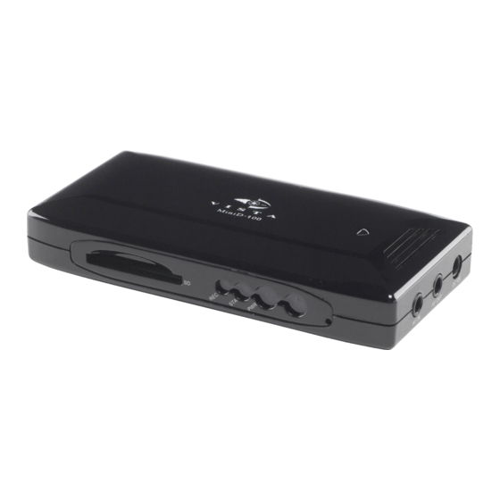
Page 7: Chapter 2: Getting To Know Your Minid400
⑧ ① This chapter briefly describes the functions of each button on MiniD400. The buttons are used to operate the basic functions of MiniD400, such as recording, playback, fast-forward, reverse play and etc. For more details on the set-up and operation of MiniD400, refer to Chapter 6, MiniD400 MENU. - Page 8 Sensor-in / Alarm-out The sensor terminal block is used to connect a sensor such as PIR to the MiniD400. This will trigger the device to event record. The alarm output terminal is used to install a single alarm device. SD Memory Slot Insert SD Card into the slot for storing data.
-
Page 9: Chapter 3: Remote Control
Chapter 3: Remote control Starts and stops MiniD400 recording. Turn the SD power off when pressing the REC button for 3 seconds. (Recording can resume after 20 seconds) Enter OSD menu. MENU On OSD menu, go to the upper menu. - Page 10 Remote Controller Functions of LIVE MODE and PLAY Remote PLABACK MODE LIVE PLAY BACK Function Stand-by Recording Stand-by Play Menu Remark RECORD MENU SEARCH MODE DOWN O: Available X: N/A ENTENT PLAY STOP PAUSE MUTE...
-
Page 11: Chapter 4: Getting Started
If you use the supplied 1GB SD Memory card, the MiniD400 can continuous record for approximately 2 hours. ● There is an exception to entering the VIEW mode at start up. If the power is turned off while MiniD400 is performing emergency recording (i.e. -
Page 12: Sd Memory Installation
Attention Do not take out the SD card or turn off MiniD400 while it is in record mode. It may damage SD card. When in record mode, turn off SD power by first pressing recording button for 3 seconds and then take... -
Page 13: Connecting Minid400 To Your Tv Set Or Monitor
Video Input/Output Connection (For TV / monitor screen display) To display images from the MiniD400, connect the video output to your monitor. Any Television with a VIDEO INPUT terminal is suitable for displaying the images. The diagram above shows the video signal connections. -
Page 14: Alarm Installation
ALARM INSTALLATION The MiniD400 has an internal switch for sounding an alarm. When a sensor is triggered, the internal alarm is also activated. There are two steps to install an alarm. 1. Connect the alarm cable to the alarm switch terminal. -
Page 15: Chapter 6: Osd Mode
MiniD400 * * * * Press the ‘MENU’ button on remote control to access to MiniD400 OSD menu. Please refer to ‘Chapter 3: Remote control’ about how to use remote control buttons. The default Password is ‘0000’. The password can be changed on ‘[SUB MENU] [PASSWORD CHANGE]’. -
Page 16: System Setup
3. SYSTEM SETUP English HIGH Configure current time and ‘DAY LIGHT SAVING’ option. On setting the current time, the field order should be as follows; 2004/02/17 = year / month / day 19:44:32 = hour /minute / second 3.1 TIME SET > DAY LIGHT SAVING SELECT ‘ON’, when you want to use day light saving time. -
Page 17: Video Setup
4. VIDEO SETUP 4CIF HIGH HIGH 30 MIN 4.1 RESOLUTION Select video resolution (4CIF / 2CIF / CIF) VIDEO INPUT (LIVE VIEW) Resolution - PAL HIGH NORMAL 4CIF 704x576 / 25fps 704x576 / 25fps 704x576 / 25fps 2CIF 704x288 / 25fps 704x288 / 25fps 704x288 / 25fps 352x288 / 25fps... -
Page 18: Video Quality
4.7 DISK OVERWRITE If overwrite is set to ON, the MiniD400 will continue recording and automatically overwriting the oldest recorded files when SD card storage capacity is full. Set to OFF, the recording will stop when the SD card is full. - Page 19 OFF when events occur. Note: In ‘Normal Close’ mode, if an intruder cuts the cable that connects the sensor to the MiniD400, the unit will start to record automatically. In ‘Normal Open’ mode, if an intruder cuts the cable that connects the sensor to...
- Page 20 6.2 FILE INDEX RENEW The index file is automatically generated and stored in the SD card when inserted into MiniD400. If the index file does not match the files actually stored in the SD card, users can synchronize the index file list and the actual file list.
- Page 21 1.1. SCREEN MESSAGE Message Description INITIALIZING… Displays when the MiniD400 is first powered up. Displays when playback and live modes are switched or when switching WAIT… between the screen mode and the OSD menu. Displays when there are no recorded files in the SD or no search result FILE NOT FOUND on search mode.
- Page 22 1.2. SCREEN ICON EMERGENCY Displays when in emergency record mode. MOTION Displays when in motion-triggered record mode. ALARM Displays when in sensor-triggered record mode. TIME Displays when in schedule record mode. Displays when there is less than 5% space remaining on the SD Card.
- Page 23 2.1.1 SEARCH FACTOR – EVENT: When you select ‘EVENT (or BOTH) on SEARCH MODE’, sub search conditions open; ALARM / MOTION / EMERGENCY / TIME (Here, the time means “scheduled time recording” using scheduling feature). More than two conditions can be selected. In this case, each condition is connected with ‘OR’ condition. * ALARM: To search recorded files triggered by alarm-in event.
- Page 24 APPENDIX TECHNICAL SPECIFICATION ITEM DESCRIPTION VIDEO Encoding H.264 Input Channel 1 Ch. Input impedance 75 ohm Unbalanced Input Format PAL/NTSC (Auto Detection), Composite, Auto detection function Maximum Input 1.0Vp-p @ 75 Ohm Unbalanced Output Channel 1 Ch. Output impedance 75 ohm Unbalanced Output Format PAL/NTSC (according to Input), Composite Maximum Output...
- Page 25 Alarm Input 1 Ch. TTL(Internal full-up) Output 1 Ch. TTL(Open collector) OPERATING MODE Searching Method Time/Event Operating Mode Live/Playback/Menu VIEWER SOFTWARE Monitoring Environment Client S/W Connection Supporting 1 Client A/Video Input 1Port, Female Stereo Phone Jack(include Jack Conversion Cable) A/Video Output 1Port, Female Stereo Phone Jack(include Jack Conversion Cable) Alarm I/O 1Port, Pluggable Terminal Block(include Plug)
- Page 26 Approximate Recording Time Table 4CIF (704x480 / D1) Recoding Time (NTSC/PAL): SANDISK – SD/SDHC MEMORY Memory Usable Memory HIGH / 4CIF / 25fps NORMAL / 4CIF /25fps LOW / 4CIF / 25fps 512 MB 480 MB 33 min 47min 1hr 26min 1 GB 960 MB 1 hr 9 min...
- Page 27 NORBAIN SD LTD 210 Wharfedale Road, Winnersh Triangle, Wokingham Berkshire RG41 5TP...
Need help?
Do you have a question about the MiniD400 and is the answer not in the manual?
Questions and answers