
Related Manuals for Vista SmartDisc 02 VLS-02DR Series


Summary of Contents for Vista SmartDisc 02 VLS-02DR Series
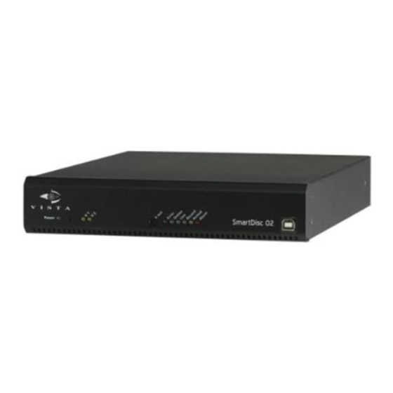
- Page 1 Vista SmartDisc 02 Digital Video Recorder/Transmitter VLS-02DR-Series Installation & Instruction Manual 1.38...
- Page 2 SmartDisc 02 Device Manual Version 1.38 (English)
- Page 4 Vista SmartDisc 02 Device Manual Vista SmartDisc 02...
-
Page 5: Limited Warranty
This manual may nevertheless include technical inexactitudes and misprints. Due to the speed of technological development, we reserve the right to include technical alterations and developments without special advance notice. Vista therefore does not make any warranty with respect to this manual or the continuing validity of these texts. Furthermore, Vista is not liable for any loss or misuse of information resulting from the use of this manual. In particular, Vista is not liable for any damages such as ... -
Page 6: Table Of Contents
................... 33 Advantages of the multi-track recording process ........33 Camera tracks ................... 33 Recording modes ..................35 Continuous recording ................36 Event triggered recording ................39 5.2 Log file ....................41 Log file command overview ............... 42 PTZ control ..................47 PTZ functions .................... 47 Camera remote control interface ............... 48 6.1 Enhanced features ................49 Control file R01 ..................49 Vista SmartDisc 02... - Page 7 General settings Part 2/2 ................58 Extras ......................58 Interface specifications ................59 10 Troubleshooting ................61 What to do in the event of malfunctions / tamper ........61 General errors ................... 62 No null modem connection possible ............62 Error diagnosis for direct connections by null modem cable ....... 63 No remote transmission possible ............... 63 Image display errors .................. 64 11 Supplement ..................65 11.1 Chronologic SmartDisc 02 firmware history ........65 Vista SmartDisc 02...
-
Page 8: How To Use This Manual
Conventions Highlighting Text referring to product names, dialog windows, buttons or illustrations is printed in bold face (e.g. SmartDisc 02, ENTER, OK, Connect). Comments and special instructions are placed in grey boxes. Additional exclamation marks (see left) indicate information of special importance. Orientation Key words and program symbols on the left will help you find your way around and make it easier to get back to sections already read. We thank you for using this hardware product and we hope that you will be satisfied with our services. Vista SmartDisc 02... - Page 9 1 How to use this manual Vista SmartDisc 02...
-
Page 10: Introduction
2 Introduction 2 Introduction Thank you for choosing a Vista security product. We use only high-quality components that meet the most stringent security requirements in our devices. They guarantee years of trouble-free operation. SmartDisc 02 is cased in a robust steel housing. It is suited to desk mounting, wall mounting, and mounting in 19 inch rack cabinets. Years of experience in developing and manufacturing CCTV software and hardware have resulted in a well thought- out and reliable product designed for a wide range of applications. SmartDisc 02 SmartDisc 02 ... - Page 11 2 Introduction Remote configuration and maintenance by IP and/or dialup connection ■ Adaptive alarm management for control inputs. Motion detection for ■ automatic dialup and recording control System and video signal monitoring ■ Camera and relay control ■ Timer control with calendar feature ■ Analog video output for manual switching, sequencer operation, and ■ alarm switching SmartDisc 02 For information on the available options for the SmartDisc 02, please refer options to the "System description" chapter (see ”Accessories” on page 11). This lists the options that can easily be fitted by the installer into the SmartDisc Vista SmartDisc 02...
-
Page 12: System Description
■ B channel The installation instructions for on-site installations are provided for both modules. External adapters Dialup adapter for integration into public and private networks (PSTN/ ■ POTS, ISDN, GSM, HSCSD) Adapter: Remote adapter with 16 remote control relays for ■ SmartDisc series devices Mounting kits 19" Mount Kit: 1RU installation kit for 19" mode mounting of up to two ■ SmartDisc 02 Vista SmartDisc 02... -
Page 13: Warranty
■ than ±5°. It is essential that you maintain the required ambient conditions for ■ outdoor installations. Protect the device against atmospheric influence. Wait for at least 10 seconds after switching off the device before turning it ■ on again. Always use the original power supply unit with the respective cable. Use it ■ only for the dedicated voltage. Ensure that the cable is intact. Never use damaged cables. Select an installation site protected against burglary and vandalism. Ensure ■ unrestricted ventilation. Make sure that specification limits are not exceeded when connecting ■ external devices. Vista SmartDisc 02... -
Page 14: Electrical Safety
Always make sure that your hands are completely dry before touching ■ SmartDisc 02, the power supply unit, cables, or sockets. Never touch these with wet hands. Disconnect the device from the power supply by pulling at the plug, not at ■ the cable. Never pull at the cable. If water or any other liquid enters the device, immediately disconnect the ■ power supply. Have the device checked by customer service. The device contains no components that can be adjusted or repaired by ■ the user. The device housing must never be opened ever. Only authorised staff may open the housing for installing ISDN Cards or ■ Audio Cards. The instructions in the included manuals must be observed. Vista SmartDisc 02... -
Page 15: System Environment
SmartDisc 02 is a standalone unit. Once installed and configured, it reacts to events, records these on a continuous or on an event-triggered basis, transmits and/or saves video and/or audio data, alarms to local and remote receiver units, and additionally logs protocols locally. Only one of the following software packets, developed by Vista especially for CCTV applications, is required for the PC based receiver/evaluation unit. SmartControl (part of SmartDisc 02 delivery) ■ software for operation, alarm verification, and configuration for single ... -
Page 16: Controls, Indicators, And Ports
3 System description 3.6 Controls, indicators, and ports Front view and description Vista SmartDisc 02 SmartDisc 02 Item Labeling/description Function SmartDisc 02 will be initialised after switch on. Depending on configuration, this may take up to 90 seconds. Avoid switching on immediately followed by switching off. This may lead to loss of data. ... - Page 17 Indicates the alarm enable status of SmartDisc 02. An illuminated LED enabled) - yellow Armed (alarm enabled) indicates alarms being forwarded to receiver units, depending on device configurations. The alarm enable status has no impact on picture recording. LED Alarm - red An illuminated Alarm LED during alarm processing indicates the SmartDisc 02 alarm status. An alarm may require confirmation by several receivers, depending on device configuration. USB port Reserved Vista SmartDisc 02...
-
Page 18: Rear View And Description
3 System description Rear view and description Vista SmartDisc 02 Item Labeling/description Function V1 in - V2 in Video input 1-4/10: BNC sockets for connecting colour or B/W video. Switching between CCIR/PAL and EIA/NTSC mode is automatic. V1 out - V2 out Video output 1-4/10: Active loop through outputs - BNC sockets - for direct connection of additional video systems/monitors. V out Video output: Analog video output with video switch and/or sequencer feature, e.g. for direct connection of a video monitor. 24 pin Terminal block with screw type terminals: Terminals for power supply, terminal block PTZ control interfaces, control inputs, relay outputs, loudspeakers (optional). Note: Pin assignment is detailed in section "Pin assignment and functionality" (see ”24 pin terminal block” on page 18) Ethernet Socket RJ-45: Ethernet interface (10/100 MBit/s) ... -
Page 19: Pin Assignment And Functionality
To activate sequencer mode, keep the control input switched to high resistance. Al in Control Alarm input for dialup with automatic switching of video input input 1 (V1 in) to a SmartControl receiver unit. Note: The operation of this input always depends on the status of arm/disarm input "Al a/d" Vista SmartDisc 02... - Page 20 SmartControl receiver unit for video inputs 1 and 2. These control inputs can be used for event recording as well as for event optimised continuous Ctrl in2 Control recording. input Pin assignment terminal block Vista SmartDisc 02...
-
Page 21: Control Inputs, Error Relay, Tamper Protection
"Log file". Viewing the Log File automatically causes reset of the error message; the error relay is de-ernergised and Error LED goes out. Refer to the manual of the respective SmartControl software for more information on log file configuration and evaluation. Tamper protection The error relay is pulled in idle - no error. Therefore the error relay can be used as tamper detector, as it automatically falls off in the event of power failure (e.g. caused by cut power lines). Depending on the error relay wiring, an interruption of the relay line itself can be reported as well. There is a theoretical possibility that tamper protection will not work if error relay switching is not consistent with the operating mode. Vista SmartDisc 02... -
Page 22: Ethernet And Isdn Interfaces
This connection mode is recommended for commissioning and service. Configuration SmartControl or SmartControl PRO software allows you to set the connection speed for remote and direct connections. In addition, AT commands can be entered for initialisation and dialling of external dialup adapters, or for defining dial mode. Refer to the respective software manual for more information. Vista SmartDisc 02... - Page 23 Ground Input Data Send Ready Output Ready to Send Input Clear to Send Direct connection SmartControl software and SmartDisc 02 automatically detect a with null modem connection between interfaces connected by null modem cable. They will cable attempt to establish a direct connection. To this end, a special cable plug code is queried when starting SmartControl software. Ensure to plug in the null modem cable before starting the device and the SmartControl software. Vista SmartDisc 02...
-
Page 24: Terminal Transp. Data/Control Interface
PRO software allows you to set important interface parameters, such as connection speed and number of data bits and stop bits. The hardware handshake lines RTS and CTS require wiring for proper operation. The operating mode in question can be selected from a drop-down menu. Refer to the respective software manual for more information. Vista SmartDisc 02... -
Page 25: Audio Connections Smartdisc 02
02 devices, you always should use a 3.5 mm stereo jack for the audio connections Line in and Line out. Please observe the following table for connection details. Connections stereo jack Input Pin 1 Pin 2 Pin 3 Line in signal no connection ground Line out signal no connection ground Vista SmartDisc 02... -
Page 26: Hard Disk
When commissioning a new hard disk in combination with a new configuration profile SmartDisc 02 unit, the factory settings stored in the SmartDisc 02 unit will be used for automatic configuration of the hard disk. After configuration with SmartControl or SmartControl PRO software you can save your personal device configuration in the form of a profile in a SmartDisc 02 flash memory and use this profile again, e.g. when changing hard disks, or for fast parameterisation of other hard disks. Reset the device as described in chapter "Device reset" if you want to reset the device to factory settings (see ”Device reset” on page 27). Vista SmartDisc 02... - Page 27 All hard disk functions, such as cyclical reset, alarm on hard disk error, activation of LED Error or the error relay, and clock error display will be deactivated. This operating mode is available only if the device does not detect any hard disk (and therefore no hard disk in the device). If SmartDisc 02 detects a functional hard disk after start up with option Use without hard disk drive activated, the option will be ignored and the hard disk will be used. If the hard disk fails during operation, all hard disk related errors will be read out until the next reset. Vista SmartDisc 02...
-
Page 28: Device Reset
You need a 9 pin Sub-D plug with pin 2 connected to pin 3, and pin 7 ■ connected to pin 8. Plug this reset plug into the interface labelled "Transp. data/Control ■ interface" (see ”Pin assignment and functionality” on page 18). Switch the SmartDisc 02 unit on and wait until LED Power on the front ■ starts flashing. Remove the reset plug. ■ Your SmartDisc 02 unit will be ready again as soon as device reset and re- ■ initialisation have been completed. Pin assignment of Transp. data/Control interface RS-232 interface Connector end view / 9 pin Sub-D socket Vista SmartDisc 02... - Page 29 3 System description Vista SmartDisc 02...
-
Page 30: Commissioning
"Pin assignment and functionality" (see ”Pin assignment and functionality” on page 18). For the installation of a camera system with PTZ control, additional information is required. Please refer to the installation instructions of the camera manufacturer and the respective supplementary documents by Vista. Also observe the information provided in chapter "PTZ control" (see ”PTZ control” on page 47). Install the SmartControl software for operation, alarm verification, and configuration from the installation CD. Please observe the installation information in the online manual of the same name. This manual is included in the installation CD. ... -
Page 31: General Configuration Information
1 MB. The device gives highest priority to image recording triggered by input ■ state change, i.e. when Edge + or Edge – recording is active. If the device detects a status change at any recording input, it will interrupt recording triggered by any different status, by status change, or by integrated motion detection in any event. For the device to positively detect control input states and status changes, ■ circuit time must be at least 0.5 seconds. Vista SmartDisc 02... - Page 32 Alarm LED will remain active until the telephone number list has been processed according to the set repeats. Select option Alarm call in case of defective Hard Disk if you want to ■ send a hard disk error message to a SmartControl station. The connection will be established approximately 45 seconds after the error occurs. If the user confirms the alarm with Report again, another call will be made 6 minutes later. If the user clicks Do not report again, the transmitter will call to report the hard disk error the next time the error is detected again with device restart. Vista SmartDisc 02...
- Page 33 Failure is reported for active cameras if the video signal has been disturbed for about 10 seconds. The check interval follows the respective recording interval. In the event of a faulty video signal, recheck takes place after 3 seconds. Recording is resumed after error elimination. For non recording video cameras failure will be reported after 60 seconds. If you require additional features, please refer to the additional configuration options in files CAMTEL.INI or CAMCTRL.INI. Refer to the respective information in the SmartControl or SmartControl PRO software online manuals. Vista SmartDisc 02...
-
Page 34: Description Of "Site Archive" Features
Each camera track can be configured with overwrite protection on ■ overrun, or for automatic overwriting. Camera tracks The SmartDisc 02 hard disk is divided into 2 camera tracks. This allows you to specify the storage space for each individual camera track. Storage capacity is displayed in GB. The illustration shows identical partitioning (factory setting) for each of the two camera tracks of a SmartDisc 02 hard disk. The required storage Vista SmartDisc 02... - Page 35 Delete all pictures If special requirements for the period of image storage must be complied older than [] days with, for example for reasons of data privacy, a maximum age can be specified for archive images per camera track. Any older images will then be deleted automatically. Vista SmartDisc 02...
-
Page 36: Recording Modes
On the basis of set recording parameters, SmartControl or SmartControl PRO software calculate the required storage capacity. The calculated values are estimates, actual values may deviate due to changes in actual image data volume, proportion of motion, and selected resolution being considered. Capacity Tool Values based on practical experience can be determined with storage capacity calculation tool Capacity Tool, developed by Vista. Vista SmartDisc 02... -
Page 37: Continuous Recording
This method can be combined with external sensors or integrated motion permanent detection to optimise storage capacity. In this case SmartDisc 02 only recording records in the event of the respective control input being activated or in the event of motion detection detecting motion. The both control inputs at the 24 pin terminal block are permanently assigned to a particular camera. Four input states can be used and configured for control. Vista SmartDisc 02... - Page 38 This image sequence is recorded This image sequence is recorded Control input closed Control input open (default) Start Start Interval Interval Duration of recording Duration of recording Camera-selektive control inputs Rear view Illustration: Permanent recording with state sensitive control input Vista SmartDisc 02...
- Page 39 Control input closed Control input open (default) Motion is detected Motion is detected Start Start Interval Interval Camera-selective Number of Number of control inputs images images Rear view Illustration: Continuous recording with motion detection and edge sensitive control input Vista SmartDisc 02...
-
Page 40: Event Triggered Recording
Later evaluation uses camera selective display. For event triggered recording, recording speed and recording duration can be specified separately for pre- and post-alarm sequences. Event triggered recording has two advantages over continuous recording: Event triggered recording with defined pre- and post-alarm sequences ■ allows for a more precise evaluation of images based on event selection. The alarm image and events before and after the alarm can be analysed directly. Event triggered recording, as a rule, only records relevant data. Evaluation ■ is therefore to the point and much faster. Vista SmartDisc 02... - Page 41 Control input closes Control input opens negative edge triggered positive edge triggered Alarm Alarm Start Start picture picture Interval Interval Interval Interval Pre-alarm Post-alarm Pre-alarm Post-alarm camera-selective control inputs Rear view Illustration: Event recording triggered by control input Vista SmartDisc 02...
-
Page 42: Log File
Other messages are optional and must be defined with SmartControl or SmartControl PRO software with menu Extras in Site archive. In the table below these messages are marked yes in column Optional. Critical messages are indirectly connected to the error relay and marked yes in column Error relay. Column Log file entry provides the text messages and optional additional information indicated by square brackets. Additional information date and time apply to all entries. Therefore each Log file entry starts with [D&T]. For all other additional information, letters (e.g. [x]) are used, which are explained in column Description. Vista SmartDisc 02... -
Page 43: Log File Command Overview
[D&T], Password disabled The reset pushbutton on the front deletes all user names and passwords. Critical messages [D&T], Track, [x], reached Overwrite protection is activated, the percentile warning threshold warning threshold has been reached for a camera track [x]. [D&T], Hard disk full, Track, Overwrite protection is activated and storage capacity for camera track [x] is depleted; no more pictures can be recorded. [D&T], Period of recording The minimum recording period for camera track reached, Track, [x] [x] can no longer be maintained. Vista SmartDisc 02... - Page 44 The clock could not be read at startup. The firmware date of manufacture has been set. This may indicate a faulty battery. [D&T], Videodecoder [x] error The video decoder has been checked at startup. This message indicates a faulty video decoder at video input [x]. Connection messages [D&T], Alarmcall failed: [x], Alarm connection to receiver with telephone AR: [y] number / IP address indicated in filed [x] could not be established. Field [y] indicates the alarm reason (AR): Possible values for [y]: Control input, camera 1 - 10: 01 - 10 Motion alarm, camera 1 - 10: 31 - 40 Alarm released by serial command, camera 1 - 10: 51 - 60 [D&T], Caller, [x], [y] Caller indicates the log in the order of the last login (0=one, 1=two etc.). Field [x] and field [y] indicates telephone number / IP address This entry is not generated for null modem connections. [D&T], Service Call, [x] The device triggered a service call to telephone number / IP Address in field [x]. Vista SmartDisc 02...
- Page 45 R= Receiver dialup ■ A= Alarm call triggered by SmartDisc 02 ■ S= Service call trigered by SmartDisc 02 ■ (every 24 hours) Field [z] = indicates the temperature observed in the device. (optional, see column "Option") [D&T], Logout, [w], [y], [z] The user indicated in field [w] terminated the see ADC connection with log in order indicated in field [y] to SmartDisc 02 (0=first, 1=second, etc.). Field [z] indicates the cause of termination: CMD = Termination by receiver software ■ command (standard) DCD = Modem, ISDN-TA, or TCP/IP alarm ■ adapter Data Carrier Detection was deactivated (standard) TI Timeout = No data transmission possible ■ for 60 seconds (error) ADC = AlarmDisConnect, caused by alarm ■ (optional feature, to be set with device configuration) Vista SmartDisc 02...
- Page 46 The Aux input indicated in field [x] has been closed closed. [D&T], Aux input [x] opened The Aux input indicated in field [x] has been opened. [D&T], V.out input closed The control output V.out has been closed. [D&T], V.out input opened The control output V.out has been opened. Status messages to the serial control [D&T], External command: The serial command XXXX was successfully XXXX,OK processed (XXXX = four-digit command) [D&T], External command: The serial command XXXX was not successfully XXXX,ERROR processed (XXXX = four-digit command) Vista SmartDisc 02...
- Page 47 5 Description of "Site archive" features Vista SmartDisc 02...
-
Page 48: Ptz Control
Please note that not all functions are supported by all camera systems. Refer to the appendix for a device-specific function overview. If your camera system is not listed, please contact your technical support centre. PTZ functions Pan and tilt ■ Variable speed ■ Zoom ■ Focus ■ Aperture control ■ Activate / deactivate auto iris ■ Actuation to base position ■ Program and call up fixed positions ■ Vector scans / program and call up rounds ■ Program and activate/deactivate privacy zones ■ Switch camera functions ■ Dome programming with OSD and key simulation ■ Vista SmartDisc 02... -
Page 49: Camera Remote Control Interface
Remote control dome cameras Illustration: Camera remote control with SmartDisc 02 Interface RS-232 Camera system data lines (e.g. Dome) are connected with terminals TxD, RxD and GND (see ”24 pin terminal block” on page 18). Please note that only one camera can be connected when using interface RS-232, for technical reasons. Interface RS-485 Camera system data lines (e.g. Dome) are connected with terminals D-, and D+ (see ”24 pin terminal block” on page 18). Up to two remote-controllable cameras can be operated at the RS-485 interface with the same data protocol with SmartDisc Refer to the enclosed installation CD for more device specific documentation on how to connect and start the camera system. Vista SmartDisc 02... -
Page 50: Enhanced Features
"C:\VISTACONT\RM\RM01" to directory "C:\VISTACONT". Note: Directory names were selected on the basis of SmartControl. Subdirectory with binary files for protocol interfaces Protocol All available protocol implementations for remote camera control can be implementations found in subdirectory "…\RM\BIN". These are binary files to be transferred to SmartDisc 02. These files are product specific and cannot be changed. You will find a full description of the R01 files and instructions on how to customise it in line with your requirements in the online manual for the PTZ Remote Adapter in the section "Control File (R01) Structure" or in the online manuals for SmartControl and SmartControl PRO in the section "Function and structure of R01 files" on the enclosed installation CD. Vista SmartDisc 02... -
Page 51: Camera System (Ptz Protocols) Overview
ULTRAK (Eurodome (6", 9", 15") / Smartscan II / Smartscan III / KD6, ■ Eurocontrol 80/160 with relay set) VCL (Dome Orbiter Microsphere and compatible VCL models) ■ Vicon (Surveyor99, Surveyer2000) ■ VideoTec (DTRXDC) ■ Videotronic infosystems (BUSTRONIC (BGALL) version 3.2 and later) ■ Vista (Vista Power Dome, PowerDome Lite & Eclipse) ■ Generic protocol ■ Additional protocols are developed for new camera systems at regular intervals. You find a current overview on the website http://www.vista-cctv.com/ Vista SmartDisc 02... -
Page 52: Web Server
Mainscreen viewing mode At least one user defined in the transmitter: Reset to logon page ■ Establishing a To establish a connection to the server, enter the symbolic name (e.g. http:/ connection /your_device.your_domain.com) or the IP address (e.g. http:// 62.214.6.12) of the device in the address bar of the Web browser. Login The login page only opens if at least one user has been defined in the transmitter. If there is no user entry, the Mainscreen viewing mode opens directly. Otherwise, you will be asked to enter your Username and Password in order to access the device (here: demo/demo). When entering your username, make sure to differentiate between lower- and uppercase letters because it is case sensitive. Enter the relevant password and click Login. Vista SmartDisc 02... - Page 53 In addition to the drop-down menus for selecting camera and image quality, this mode also has a drop- down menu for selecting fixed positions (Preset 1 to Preset 9) – if a PTZ protocol is activated. Fixed positions can only be controlled if a PTZ camera is selected and fixed positions are defined. Log out by clicking this button. Vista SmartDisc 02...
- Page 54 Clicking the Logout button logs the current user off the transmitter. The Login screen then opens. Automatic In addtion to being able to activate the Web Server function, you can also disconnect configure additionally an Automatic disconnect time for web-browser connections (see ”Web Server” on page 51). After the specified time, the disconnection is indicated by this message. Click the Reconnect button to re-establish a connection to the selected transmitter. Vista SmartDisc 02...
- Page 55 7 Web Server Vista SmartDisc 02...
-
Page 56: Technical Data Smartdisc
Transmission, recording General Video and audio transmission, simultaneous recording and replay of video; online evaluation with local and/or remote receiver stations MultiCast, Multi-Unicast Simultaneously up to 6 IP connections, or 5 IP and 1 dialup connection, or 4 IP and 2 dialup connections Web Server Up to four simultaneous IP connections via PC, Smartphone or PDA browser (in addition to five standard connections)) Video transmission of With up to 50 fps via IP (LAN internet, DSL) and dial-up connections (PSTN/ live and archive images POTS, ISDN, GSM, HSCSD/ UMTS) Recording speed Up to 50 fps depending on compression mode, image content and bit rate Recording media Integrated 2.5" hard disk (E)IDE drive (120 GB) with adaptive multi-track management (2 tracks) Trigger recording/ Contact trigger, integrated motion detection, external serial commands transmission and timer (weekly calendar) Recording modes Event triggered up to 50,000 events per camera with pre-alarm and post- alarm or continuous recording, all modes with integrated timer (weekly calendar) Recording parameters Event-triggered recording: Interval = 0-999 sec and duration = 1-999 sec (value "0" = maximum separately adjustable for pre-alarm and post-alarm; continuous recording: speed) Interval = 0-999 sec timer controlled (also event optimized) Callback Automatic callback to pre-programmed receiver station with SmartControl software Vista SmartDisc 02... - Page 57 Control outputs 2 relays - system error and/or remote control (switch on screw type bar), max. 30 V DC/1 A, 60 V DC/0.3 A, 125 V AC/0.5 A General Operating system / Embedded Linux/proprietary hardware (no PC) system design Controls and indicators Pushbutton for manual camera selection and status LEDs Setup and software Via local and/or remote receiver station with WAN and/or LAN terminals update Protocols Transmitter side event protocols of essential functions and device status Power supply External power supply unit, 100-240 V AC, 50/60 Hz, 12 V DC max. 3.5 A, 42 W Voltage range 11.4 V DC … 12.7 V DC Ambient temperature +5°C … +40°C (+41 … +104°F) Housing/mounting Desktop and wall mounting 221 x 44 x 270 (WxHxD mm) 19" mounting: ½ 19" x 1HE x 275 mm (WxHxD) Weight 1.5 kg including hard disk Certification CE (EN 50130-4, EN 50081-1, EN 60950) Options ISDN Card, Audio Card, 19" Mount Kit, SmartMount Kit, R16 Adapter, external adaptor for dialup connections for serial interface connection Vista SmartDisc 02...
-
Page 58: Factory Settings
Number repeats = 4; interval between calls (s) = 4; interval between two Repeats (s) = 30s; Always call all telephone numbers = not active Camera-specific settings Live image quality Per camera = 512x256+; per group = 512x256+; per set of 4’ = 512x256+; conditional refresh mode = active Camera settings For all cameras: Camera= active; camera name= "Camera 1", "Camera 2"; brightness= 100%; contrast= 100%; colour= on Motion detection Not active; detection areas = all active (only visible on activation of motion zones fields for the corresponding camera) Privacy zones Not defined Alarm Alarm inputs Alarm enable input: Status= enabled; connect= not active ; active if= control input open (high active) Alarm input: connect= active; active if= control input closed (low active) Camera alarm For all cameras: Trigger= normally open contact; connect= not active Motion For all cameras: motion alarm= not active; sensitivity= motion – Vista SmartDisc 02... -
Page 59: Site Archive
PTZ control No PTZ protocol assigned; Deactivate PTZ = not active Serial channel Baud rate= 9,600; Mode= 8N1 (8 data bits, no parity, 1 stop bit); Function = Transparent Video monitor Sequencer operation= active; video camera 1= active; all other cameras= not active; all switch times set to 2 s Extras Log file Last caller= not active; Change of inputs = not active; Only when armed = not active; Temperature = active; Video signal loss detection = not active; Service Alarm call in case of defective Hard Disk = active; Routine call every 24 hours = not active; Extra Operation without hard disk drive = not active; Hang-up and redial on alarm = not active; Release access for PTZ, Relay, Audio after [] seconds = 60; Software video signal lost detection = Immediately Vista SmartDisc 02... -
Page 60: Interface Specifications
115,200 Bit/s 10 MBit/s Transmitter permitted ± 25 V – 7…12 V driver output voltage Driver output signal ± 15 V ± 6 V without load Driver output signal with ± 15 V ± 2 V load Driver load 3…7 KOhm 54 Ohm Receiver input voltage ± 15 V – 7…12 V Sensitivity ± 3 V ± 200 mV Input resistance 3…7 KOhm 12 KOhm Note: As technical properties of serial interface components vary, transmission rate and line length data provided here constitute maximum limits. Vista SmartDisc 02... - Page 61 9 Factory settings Vista SmartDisc 02...
-
Page 62: Troubleshooting
Error will be indicated by LED Error and reported to a SmartControl station (depending on configuration) by the Error relay. Error on hard disk access The error will be indicated by LED Error, written to the log file on the hard disk (if still possible) and forwarded to a SmartControl station (depending on configuration). Power failure Error relay opens (if so configured). Warning for set image threshold reached The condition will be indicated by LED Error and reported by the Error relay (depending on configuration). With a warning threshold set to <100%, the device will continue operation until the respective camera track on this disk is full. Then recording on this track will be stopped until deletion will release recording again. Video signal failure The condition will be indicated by LED Error and reported by the error relay (depending on configuration). The device is switched off briefly and switched Error relay opens (if so configured). back on immediately. Fast switching off and on has the impact of a power failure. Wait for about 10 seconds after switching off the device before switching it back on again. Vista SmartDisc 02... -
Page 63: General Errors
1. Install the latest version of SmartControl cannot be evaluated archive software installed or SmartControl PRO software Install the latest Smart Player software No null modem connection possible A null modem connection between the transmitter and a SmartControl receiver station is only possible with an original null modem cable (indicated by an orange-red sticker on the cable). Standard commercial null modem cables cannot be used. Refer to the pin assignment of the null modem cable in this manual (see “Direct connection with null modem cable” on page 22). Vista SmartDisc 02... -
Page 64: Error Diagnosis For Direct Connections By Null Modem Cable
02 switched off, not set to factory Check your SmartDisc settings, or faulty. 2. Test the COM port with another terminal 4. Null modem connected to device and program (e.g. mouse or modem active device and HyperTerminal). 3. Switch the transmitter off. Connect all cables properly. Switch the transmitter back on again. No remote transmission possible Problems with remote data transmission by telephone and computer networks can be caused on the transmitter side and on the receiver side. The SmartControl and SmartControl PRO software manuals provide detailed troubleshooting advice for locating errors. Error elimination is described there as well. Vista SmartDisc 02... -
Page 65: Image Display Errors
4. Contact your retailer to have your SmartDisc 02 device inspected. The displayed images The SmartDisc 02 device is Consult your dealer. consist of coloured faulty. rectangles. The displayed images 1. The PC monitor is 1. Correct the settings of your PC monitor. are too light or too configured incorrectly. 2. Use different cameras or correct the signals by dark. 2. The camera signals from using appropriate wiring, different cables, etc. the cameras connected to Check the configuration of the SmartDisc 02 the SmartDisc 02 device device, particularly with regard to the video are too strong or too inputs. weak. SmartDisc 02 settings for brightness and contrast, etc. are inappropriate. Vista SmartDisc 02... -
Page 66: Supplement
11 Supplement 11 Supplement This chapter provides information that could not be included in the manual at the time of printing. 11.1 Chronologic SmartDisc 02 firmware history ........65 11.1 Chronologic SmartDisc 02 firmware history SmartDisc 02 firmware 1.38 Initial release ■ Vista SmartDisc 02... - Page 67 11 Supplement Vista SmartDisc 02...
- Page 68 Vista Norbain House Eskdale Road Winnersh Triangle Wokingham Berkshire RG41 5TS England 08.3143-E Phone: +44 (0) 118 944 0123 Printed in Germany Fax: +44 (0) 118 944 0999...
Need help?
Do you have a question about the SmartDisc 02 VLS-02DR Series and is the answer not in the manual?
Questions and answers