Table of Contents
Advertisement
SPECIFICATIONS ................................................................................................................................................ 2
EXTERNAL DIMENSIONS ................................................................................................................................... 3
WIRING DIAGRAM ............................................................................................................................................... 3
HOW TO OPERATE ............................................................................................................................................. 4
OPERATION INSTRUCTUINS ............................................................................................................................. 5
INSTALLATIOIN INSTRUCTIONS ...................................................................................................................... 12
DISASSEMBLING PROCEDURE ....................................................................................................................... 14
HOW TO REPAIR REFRIGERATION ................................................................................................................ 18
ELECTRICAL COMPONENT TEST .................................................................................................................... 21
MICROCOMPUTER CONTROL SYSTEM .......................................................................................................... 22
TROUBLESHOOTING GUIDE ............................................................................................................................ 26
COOLING LOAD ESTIMATE FORM ................................................................................................................... 31
RUNNING CONDITION ....................................................................................................................................... 33
PACKING AND ACCESSORIES ......................................................................................................................... 34
REPLACEMENT PARTS LIST ............................................................................................................................ 35
SHARP CORPORATION
SERVICE MANUAL
MODEL
In the interests of user-safety (Required by safety regulations in some
countries) the set should be restored to its original condition and only
parts identical to those specified should be used.
TABLE OF CONTENTS
This document has been published to be used for after
sales service only.
The contents are subject to change without notice.
1
AIR CONDITIONER
AF-06CSL
AF-06CSL
S3210AF06CSL/
Page
Advertisement
Table of Contents

Related Manuals for Sharp AF-06CSL


Summary of Contents for Sharp AF-06CSL
-
Page 1: Table Of Contents
AF-06CSL SERVICE MANUAL S3210AF06CSL/ AIR CONDITIONER AF-06CSL MODEL In the interests of user-safety (Required by safety regulations in some countries) the set should be restored to its original condition and only parts identical to those specified should be used. TABLE OF CONTENTS Page SPECIFICATIONS .............................. -
Page 2: Specifications
AF-06CSL SPECIFICATIONS Models AF-06CSL Cooling capacity BTU/h 6000 Moisture removal Pints/h ELECTRICAL DATA Phase Single Rared frequency Rated voltage Volts Rated current Amps Rated input Watts Power factor BTU/Wh 11.0 COMPRESSOR Type (Hermetically sealed rotary type) Model, Motor output 39R141AA-04P, 460W... -
Page 3: External Dimensions
AF-06CSL WIRING DIAGRAM POWER SUPPLY CORD WIRE COLOR 3A 125V 115V 60Hz : BLACK NON RIBBED : BLUE CONTROL : RED BOARD UNIT : WHITE : GREEN : GRAY OVERLOAD : ORANGE PROTECTOR THERMISTOR COMPRESSOR ( ROOM TEMP ) MOTOR... -
Page 4: How To Operate
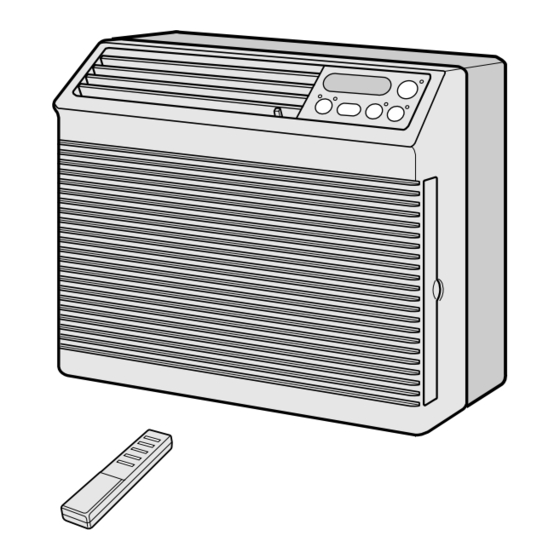
AF-06CSL HOW TO OPERATE PARTS NAMES UNIT 1Front Cabinet 2Air Inlet (Indoor Side) 3Horizontal Louvers 4Vertical Louvers 5Air Outlet (Indoor Side) 6Control Panel 7Rear Cabinet 8Air Inlet (Outdoor side) 9Filter (Pull the filter handle to the right to remove.) 0Filter Handle... -
Page 5: Operation Instructuins
AF-06CSL HOW TO OPERATE COOLING OPERATION POWER Touch POWER ON/OFF pad. indicator SELECTOR indicator • The unit is preset at 74°F and HIGH COOL. This will show in the display when the power is first turned on. POWER • POWER indicator and SELECTOR ON/OFF indicator (COOL) will light. -
Page 6: To Change Fan Speed And Operation Mode
AF-06CSL TO CHANGE FAN SPEED AND OPERATION MODE SELECTOR indicator During operation Touch SELECTOR pad and select the operation mode and fan speed. POWER ON/OFF • SELECTOR indicator and display will light in order as you touch. COOL / FAN... -
Page 7: Energy Saver
AF-06CSL ENERGY SAVER During normal operation, the thermostat automatically controls cooling and the fan runs continuously. When the ENERGY SAVER is selected, the thermostat automatically controls cooling and the fan automatically stops when the compressor is not operating. (Fan will stop 30 seconds after the compressor stops. -
Page 8: On Timer Operation
AF-06CSL ON TIMER OPERATION • This unit has a built-in timer that can be programmed to start the unit up to 12 hours in advance. You can set the timer to start in increments of 30 minutes (0.5 hours) up to 9.5 hours in advance of the start time, or in 1 hour increments from 10 to 12 hours in advance of the start time. -
Page 9: Off Timer Operation
AF-06CSL OFF TIMER OPERATION • This unit has a built-in timer that can be programmed to shut the unit off up to 12 hours in advance. You can set the timer to stop in increments of 30 minutes (0.5 hours) up to 9.5 hours in advance of the stop time, or in 1 hour increments from 10 to 12 hours in advance of the stop time. -
Page 10: Using The Remote Control
AF-06CSL USING THE REMOTE CONTROL INSTALLING BATTERIES Use two size-AAA (R03) batteries. Remove the battery compartment cover. Insert the batteries in the compartment, making sure the polarities are properly aligned. Battery compart- ment cover Replace the cover. NOTES: • The battery life is approximately one year with normal use. - Page 11 AF-06CSL OPERATING WITH THE REMOTE CONTROL TRANSMITTER POWER ON/OFF POWER ON/OFF button Push to start or stop the operation. TEMP. TEMPERATURE setting button TEMP. Raise temp. setting 1°F at a time. TEMP. TEMP. Lower temp. setting 1°F at a time.
-
Page 12: Installatioin Instructions
AF-06CSL INSTALLATION INSTRUCTIONS ACCESSORIES Accessories Q'ty Right closure assembly Left closure assembly Window sash foam seal Window sash foam seal (adhesive type) Bottom gasket Screws (L=1", 25.4mm) Screws (L= ", 10mm) Base pan angle Remote control Battery Remote control hook SUGGESTED TOOLS 1. - Page 13 AF-06CSL 3. Open the window sash and place the air conditioner 6. Loosen screws on both sides of the cabinet, then on the sill. hang the base pan angle on and secure the screws again. Balance the unit on the sill and close the window sash securely behind the top angle.
-
Page 14: Disassembling Procedure
AF-06CSL DISASSEMBLING PROCEDURE CAUTION: DISCONNECT THE ROOM AIR CONDITIONER FROM THE POWER SUPPLY BEFORE ANY SERVICE 1. Unscrew the 2 screws holding the front panel on each 5. Remove the control panel. side. 6. Unscrew the 5 screws. 3 screws are holding the control box at the top and right side. - Page 15 AF-06CSL 9. Cut the wire fixing band, slide the control box rightward 13. Unscrew the 3 screws holding the condenser shround. and remove. And remove the condenser shround. 10. Unfasten the one nut at the top of the compressor 14. Unscrew the 5 screws. 2 screws are holding the holding the terminal cover.
- Page 16 AF-06CSL 17. Unscrew the screw holding the centrifugal fan. (Remove by using a driver or wrench) 18. Remove the caseing. 19. Unscrew the 4 screws holding fan motor.
- Page 17 AF-06CSL DISASSEMBLING THE CONTROL BOX 1. Unscrew the 2 screws holding the control box cover. 5. Unscrew the 1 power supply cord grounding screw. Unscrew the earth screw. Unscrew the 1 screw holding CAUTION: DISCHARGE THE FAN MOTOR CAPACITOR AND the capacitor clamp.
-
Page 18: How To Repair Refrigeration
AF-06CSL HOW TO REPAIR REFRIGERATION Before sealed system work can be preformed a refrigerant recovery EPA and LOCALLY approved certification is required, additionally, EPA and LOCALLY approved refrigerant recovery equipment is required. SEALED SYSTEM REPAIR Sealed system repairs should be properly diagnosed before entering into a repair of the system. - Page 19 AF-06CSL PROPER FLUXING Flux is necessary when using silver solder; it is not required when using silfos on copper to copper joints. 3/8" To do a good job the flux should cover the tube surface SILVER ALLOY completely. Be careful not to introduce any flux inside the tubing.
- Page 20 AF-06CSL Type of evacuation methods 1. Piston Type Compressor No good. System parts must be above 110˚F. DIAL-CHARGE ELECTRIC CHARGING CYLINDER 2. Rotary Vacuum Pump Disavantages. VACUUM GAUGE Low CFMC. 4 oil gets dirty. LOW SIDE HIGH SIDE GAUGE GAUGE 3.
-
Page 21: Electrical Component Test
AF-06CSL ELECTRICAL COMPONENT TEST RUNNING CAPACITOR AND FAN CAPACITOR CAUTION: DISCHARGE THE RUNNING CAPACITOR AND FAN CAPACITOR BEFORE TOUCHING CAPACITOR OR WIRING. (1) Discharge capacitor by shorting terminals. (2) Take the wires off the capacitor terminals. (3) Set the selector switch of a volt-ohm-meter (or a tester) on the resistance range. -
Page 22: Microcomputer Control System
AF-06CSL MICROCOMPUTER CONTROL SYSTEM 1. Temperature control characteristic 3. Fan speed Fan speeds are given by the fan motor, “H”, “M” and 1-1 COOL operation “L”, which are available in the following operation In the “COOL” mode, the thermostat circuit is controlled mode. - Page 23 AF-06CSL 6. Safety start When you turn the air conditioner OFF and restart again soon, wait at least 3 minutes before the cooling operation starts. 7. Test mode Keep pushing both buttons “POWER ON/OFF” and “ " ” and supply the power, the system will go to the test mode.
- Page 24 AF-06CSL...
- Page 25 AF-06CSL DPWBFA244JBKZ QPWBFB438JBZZ BCN2 DPWBA244JBKZ QPWBFB438JBZZ Printed Wiring Board...
-
Page 26: Troubleshooting Guide
AF-06CSL TROUBLESHOOTING GUIDE No cooling (Operation not at all.) Measure the power supply under 100V voltage at receptacle. 120V(over 100V) The house fuse or circuit not open. breaker open ? open Is it proper current capacity of the Ask the power supply house fuse or the circuit breaker ? company for check. - Page 27 AF-06CSL No cooling (Fan operate but the compressor doesn't operate.) under 100V Measure the power supply voltage at receptacle. Ask the power supply company for check. 120V(over 100V) insufficient Is it sufficient current capacity of power equipment ? Ask the power supply Is it small wiring for power company for check.
- Page 28 AF-06CSL No cooling (The compressor operate but the fan motor doesn't operate) crack at the solder part disconnecting the connector Check BNC1 on PWB ass'y Repair with over solder. Connect the connector properly. Check the fan motor capacitor. Change the fan motor...
- Page 29 AF-06CSL Insufficient cooling(Both compressor and compressor operate) too high Check the temperature setting. Set the lower temperature. dirty Check the air filter. not dirty Clean the air filter. there is Is there high heat source or any object restricting heat radiation near the unit.
- Page 30 AF-06CSL Excessive vibration or Abnormal noise At fan only mode, Excessive vibration or Abnormal noise dirty Check the air filter not dirty Clean the air filter. Check rotating direction of centrifugal fan.(to clockwise) Check the fan motor connector. Connect properly.
-
Page 31: Cooling Load Estimate Form
AF-06CSL COOLING LOAD ESTIMATE FORM INSTRUCTIONS FOR USING COOLING LOAD ESTIMATE FORM FOR ROOM AIR CONDITIONERS (AHAM PUB. NO. RAC-1) A. This cooling load estimate form is suitable for estimating the cooling load for comfort air conditioning installations which do not require specific conditions of inside temperature and humidity. - Page 32 AF-06CSL BTU/Hr FACTORS (Quantity HEAT GAIN FROM QUANTITY x Factor) Inside Outside (Area a Shades Shades Shades Factor) 1. WINDOWS: Heat gain from sun. sq ft Northeast only sq ft Southeast sq ft South largest Southwest load sq ft Southeast...
-
Page 33: Running Condition
AF-06CSL RUNNING CONDITION Note: 1. Select mode of the Running Condition of a Room Air Conditioner. SELECTOR ....................HIGH COOL THERMOSTAT ....................64˚F 2. Data of Performance Curve is measured between 40%RH and 70%RH. If you measure the Room Air Conditioner above or below this rating, the data may miss the range of the performance curve. -
Page 34: Packing And Accessories
AF-06CSL PACKING AND ACCESSORIES TOP PAD ASSEMBLY (DPADBA004JBFZ) Top pad L Top pad R Accessories Operation manual Window sash foam seal Window sash seal Bottom gasket Screws Base pan angle Right closure assembly Left closure assembly Remote control Battery Remote control hook... -
Page 35: Replacement Parts List
AF-06CSL REPLACEMENT PARTS LIST REF. NO. PART NO. DESCRIPTION Q'TY CODE CABINET AND UNIT PARTS 1- 1 DCHS-A441JBTA Base pan ass’y 1- 2 CCAB-A316JBKZ Cabinet ass’y 1- 3 LANG-A503JBTA Top inst. angle 1- 4 PSEL-C357JBEZ Cabinet insulator 1- 5 HPNLCA802JBFC... -
Page 36: Accessory Parts
AF-06CSL REF. NO. PART NO. DESCRIPTION Q'TY CODE 3-14 LHLD-A315JBF0 Thermistor holder 3-15 PSEL-C289JBEZ Evaporator insulator 3-16 LBND-A042JBE0 Wire fixing band ACCESSORY PARTS 4- 1 TINSEA300JBRZ Operation manual 4- 2 LANGAA011JBFE Left closure frame 4- 3 LANGAA012JBFE Right closure frame... - Page 37 AF-06CSL CABINET PARTS 4-10 4-16 4-11 4-17 4-12 4-14 6-11 4-18 4-15 4-13 6-13 6-10 6-11 1-34 1-10 1-11 1-12 1-30 1-26 1-33 1-26 1-24 1-13 1-25 1-35 1-14 1-17 1-21 1-19 1-16 1-18 1-22 1-20 1-29 1-15 1-32 1-28...
- Page 38 AF-06CSL CONTROL BOX PARTS 2-17 2-10 2-12 6-12 2-11 2-16 2-10 2-13 2-14...
- Page 39 AF-06CSL CYCLE PARTS 6-14 3-13 3-12 3-11 3-10 2-15 3-15 6-15 3-14 6-15 3-16...
- Page 40 No part of this publication may be reproduced, stored in retrieval systems, or transmitted in any form or by any means, electronic, mechanical, photocopying, recording, or otherwise, without prior written permission of the publisher. ’02 SHARP CORP. (3S0.85E) Printed in U.S.A.
Need help?
Do you have a question about the AF-06CSL and is the answer not in the manual?
Questions and answers
Do I have to add water anywhere for this Unit?