
Related Manuals for Nu-Way PO160


Summary of Contents for Nu-Way PO160
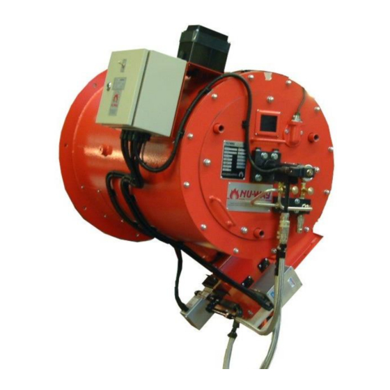
- Page 1 Installation & Maintenance Manual PO Series Automatic Oil Burner Fully Modulating Oil Burner Tel: +44 (0) 1905 794331 Fax: +44 (0) 1905 794017 Email: info@nu-way.co.uk Web: www.nu-way.co.uk...
-
Page 2: Table Of Contents
C C C C C ONTENTS ONTENTS ONTENTS ONTENTS ONTENTS ................A.4 MPORTANT NFORMATION ........................A.4 AFETY ..................A.4 MERGENCY NSTRUCTIONS (B.E.D.) ............A.4 UROPEAN OILER FFICIENCY IRECTIVE ................. B.1 ENERAL NFORMATION ....................... B.2 NTRODUCTION ....................... B.2 EATURES Burner Designation ......................B.2 Burner Capacity ........................ - Page 3 ........................D.2 AFETY ..................D.2 MERGENCY NSTRUCTIONS ......................D.2 NSPECTION ..................... D.3 NITIAL ETTINGS ......................D.3 ....................... D.3 General ..........................D.3 Oil Supply Temperature And Pressure ................. D.4 Initial Checks ........................D.4 ....................D.5 ODULATING ................... D.6 OMMISSIONING THE URNER Checking The Flame Signal ....................
-
Page 4: Important Information
It is essential that the following instructions and adjustments are carried out by qualified engineers that are experienced in forced draught pressure jet oil burner commissioning. Nu-way cannot be held responsible for any consequential damage, loss or personal injury as a result of customers failing to follow these instructions, or as a result of misuse. -
Page 5: General Information
ENERAL NFORMATION PO Series General Information Page B.1... -
Page 6: Ntroduction
For more information contact Nu-Way. accurately repeated. The temperature or pressure of the boiler must be monitored by the control... -
Page 7: Ite Onditions Nd Ervices
S S S S S C C C C C A A A A A S S S S S Oil Deliveries ONDITIONS ONDITIONS ERVICES ERVICES ONDITIONS ONDITIONS ONDITIONS ERVICES ERVICES ERVICES It is good practice to shut down boilers whilst the delivery of oil is made and allow 30 minutes for oil Flue and Chimney Requirements sediment to settle out before re-starting the... -
Page 8: Electrical Power Supply
(not supplied floor/wall mounted burner control panel by Nu-way). a pumping and heating unit, or pumping unit For PO burners, place the pumping and only for distillate oil burners, is supplied as a... - Page 9 UPPLEMENT TO ANDBOOKS PECIFICATION HANGES IRING OLOURS In accordance with the Requirements for Electrical Installations BS 7671:2001 Amendment No 2 (the IEE wiring regulations), wiring colour coding has been amended to Brown (L) and Blue (N) for single phase power circuits and Brown (L1) Black (L2) and Grey (L3) and Blue (N) in three phase power circuits from 1 June 2006.
-
Page 10: Electrical Power Supply
Electrical Power Supply Connect the power supply to the burner observing all applicable Codes and Standards. Reference should be made to the wiring diagrams provided in the instruction pack that is supplied with all P Series burners and to those wiring diagrams in the appliance manufacturer’s instructions. - Page 11 B B B B B D D D D D C C C C C URNER URNER URNER ESIGNA ESIGNA ESIGNATION TION TION TION URNER URNER ESIGNA ESIGNA TION PO Series General Information Page B.6...
- Page 12 O O O O O H H H H H T T T T T A A A A A P P P P P IL IL IL IL IL ANDLING ANDLING EMPERA EMPERA TURES TURES RESSURES RESSURES ANDLING ANDLING ANDLING EMPERA EMPERATURES...
- Page 13 T T T T T P P P P P O O O O O R R R R R M M M M M YPIC YPIC YPICAL UMPED UMPED UMPED IL IL IL IL IL YPIC YPIC UMPED UMPED PO Series General Information Page B.8...
- Page 14 PO Series General Information Page B.9...
- Page 15 AAD \PFinal\B_Gen\PO\B_Gen.pmd 250504A PO Series General Information Page B.10...
-
Page 16: Technical Specification
ECHNICAL PECIFICATION Page C.1 PO Series Technical Specification... - Page 17 B B B B B S S S S S S S S S S URNER URNER URNER PECIFIC PECIFICA A A A A TION PECIFIC TION TION TION HEET HEET HEET URNER URNER PECIFIC PECIFIC TION HEET HEET Page C.2 PO Series Technical Specification...
-
Page 18: Urner Nd Omponent Dentification
Modulating Unit specified, (see diagrams on Page C.10 Distillate Oil Control Train Schematic and on Page C.11 Residual The Nu-way modulating unit consists of a reversible Oil Control Train Schematic) consisting of : servomotor, which is directly coupled to the pumping/heating set camshaft of the modulating unit. - Page 19 motorised spill control valve The pump should not be started when the oil is cold as this can lead to damage to the pump and non-return valve couplings. The oil must be supplied and Pumping Set For Class D Fuel maintained at the temperature and pressure given The pump unit is free standing and comprises : in the Table on Page B.8.
-
Page 20: Flame Monitor
Oil Nozzle The burner sequence controller will then continue to its normal operating position (i.e. it continues The oil nozzle is of the spill-back type and is fitted to supervise the control functions and is therefore to the front end of the inner assembly and located able to shutdown the burner safely should this be in the flame tube. -
Page 21: To Enter A New Parameter
Alter the red display using the up/down buttons At any point in the procedure the original to show the new required set point, press exit or operating display can be obtained by letting the let the unit time out to return to the basic display unit time out, the value in the display at the time which should be the new set point figure. - Page 22 B B B B B A A A A A C C C C C I I I I I URNER URNER URNER OMPONENT OMPONENT OMPONENT DENTIFIC DENTIFICA A A A A TION DENTIFIC TION TION TION URNER URNER OMPONENT OMPONENT DENTIFIC DENTIFIC...
- Page 23 B B B B B C C C C C I I I I I D D D D D URNER URNER URNER AND OMPONENT OMPONENT OMPONENT DENTIFIC DENTIFIC DENTIFICA A A A A TION TION TION TION ET ET ETAIL URNER URNER...
- Page 24 O O O O O P P P P P IL IL IL IL IL UMPS UMPS UMPS UMPS UMPS Page C.9 PO Series Technical Specification...
- Page 25 All interconnecting pipework must have a minimum bore of 19mm (3/4") and must be pressure rated for 42kg/cm². Pipework connections between the burner oil system and the separate pumping set are not supplied by Nu-Way. Connections to the ring main on the air separator bottle air 1" BSP . Page C.10...
- Page 26 42kg/cm². Pipework connections between the burner oil system and the separate pumping set are not supplied by Nu-Way. Connections to the ring main on the air separator bottle air 1" BSP . On residual fuel oil burners this pipework must be maintained at the burner atomising temperature and in the case of class F and class G fuels must also be trace heated.
- Page 27 D D D D D O O O O O P P P P P S S S S S ISTILL ISTILL ISTILLA A A A A TE TE TE TE TE IL IL IL IL IL UMPING UMPING UMPING ET ET ET ET ET ISTILL ISTILL...
- Page 28 R R R R R O O O O O P P P P P /H /H /H /H /H S S S S S ESIDU ESIDUAL ESIDU AL AL AL AL IL IL IL IL IL UMPING UMPING UMPING EATING TING TING...
- Page 29 B B B B B S S S S S C C C C C & S & S & S L L L L LAL2.25 AL2.25 AL2.25 AL2.25 & S & S AL2.25 URNER URNER URNER EQUENCE EQUENCE EQUENCE ONTROLLER ONTROLLER ONTROLLER...
- Page 30 B B B B B H H H H H URNER URNER URNER URNER URNER Page C.15 PO Series Technical Specification...
- Page 31 E E E E E S S S S S D D D D D LECTRODE LECTRODE LECTRODE ETTING ETTING ETTING ET ET ETAIL LECTRODE LECTRODE ETTING ETTING Page C.16 PO Series Technical Specification...
- Page 32 M M M M M C C C C C S S S S S RWF40 RWF40 RWF40 RWF40 RWF40 ODUL ODUL ODULA A A A A TION TION TION TION ONTROLLER ONTROLLER ONTROLLER ANDIS ANDIS AND ANDIS T T T T T AEF AEFA A A A A ODUL ODUL...
- Page 33 M M M M M U U U U U ODUL ODULA A A A A TING ODUL TING TING TING ODUL ODUL TING (Cams shown in the Low Oil Cam Adjusting Screw Flame Position) Oil Cam Hub Oil Cam - A Air Cam - B Oil Spill Back Regulating Valve...
- Page 34 Page C.19 PO Series Technical Specification...
- Page 35 AAD PFinal\C_Tech\Po\RWF40\C_Tech.pmd 250504A Page C.20 PO Series Technical Specification...
-
Page 36: Commissioning
OMMISSIONING P Series Commissioning Page D.1... -
Page 37: Ndividual Etting Ecord
Ensure that all necessary tools and test oil burners. equipment are available and ready for use. Nu-way can accept no responsibility for Essential items include temperature consequential loss, damage or injury, which results measuring instruments for measuring flue gas... -
Page 38: Nitial Ettings
I I I I I S S S S S Remove the flame detector from the burner, NITIAL NITIAL ETTINGS ETTINGS NITIAL NITIAL NITIAL ETTINGS ETTINGS ETTINGS expose the detector to a flame or simulated To prepare the burner for commissioning: flame. -
Page 39: Initial Checks
C C C C C B B B B B Initial Checks OMMISSIONING OMMISSIONING URNER URNER OMMISSIONING OMMISSIONING THE OMMISSIONING URNER URNER URNER Remove the access lid on the modulating cam box unit. Establish fuel supply to the burner. Establish Establish electrical supply to the control electrical supply to the control panel and switch panel and switch the burner on. -
Page 40: Checking The Flame Signal
Reset the sequence controller and allow the Establish the electrical supply and switch on burner to start pump. Immediately the burner the burner. Allow the burner to light and starts, switch the ‘hand/auto’” selector to the operate normally. ‘hand’ position and hold the low flame until Observe the reading on the micro-ammeter the appliance is ready to accept high flame. -
Page 41: Final Checks
12. Remove pressure measuring Customer and plant details, including any equipment.Final Checks serial numbers. Operating levels and settings, including flue Final Checks gas analysis information. Check that all covers have been replaced and that all locking devices are secure. This report shall be passed to the person Check the operation of the appliance control responsible for the plant. - Page 42 P Series Commissioning Page D.7...
-
Page 43: Oil
C C C C C S S S S S OMMISSIONING OMMISSIONING OMMISSIONING HEET HEET HEET IL IL IL IL IL OMMISSIONING OMMISSIONING HEET HEET The details below are to to be completed by the Commissioning Engineer. The completed sheet must then be photocopied and a copy forwarded to the appliance manufacturer. - Page 44 AAD PFinal\C_Tech\Po\RWF40\D_Comm.pmd 250504A P Series Commissioning Page D.9...
- Page 45 Page 10 P Series...
-
Page 46: E : O Peration A Nd M Aintenance
E : O PERATION AINTENANCE PO Series Operation And Maintenance Page E.1... -
Page 47: Automatic Modulation
N N N N N O O O O O Combustion Air Pressure Switch ORMAL ORMAL PERA PERA TION TION ORMAL ORMAL ORMAL PERA PERA PERATION TION TION Check that the electrical supply to the control panel off and that the burner is off. Automatic Modulation Remove the air pressure switch cover. -
Page 48: Burner Inner Assembly
The fan motor rotates in the direction of the arrow is now ready for operation and remove the guide printed on the Nu-way nameplate mounted on the rods. Switch on the electrical and fuel supplies to fan casing. If the direction of rotation is incorrect, the burner. -
Page 49: Fan Motor Starts And Burner Goes To Lockout
ARTS ARTS ARTS The burner controller is not faulty For spare parts contact Nu-way's Parts And If there is an ignition spark but no start flame check Components Division at the address and telephone The oil supply to the burner number listed on the rear cover of this manual. -
Page 50: Urner Ervice Ecord
B B B B B S S S S S R R R R R URNER URNER URNER ERVICE ERVICE ERVICE ECORD ECORD ECORD URNER URNER ERVICE ERVICE ECORD ECORD PO Series Operation And Maintenance Page E.5... - Page 51 Page E.6 PO Series Operation And Maintenance...
- Page 52 PO Series Operation And Maintenance Page E.7...
- Page 53 N N N N N OTES OTES OTES OTES OTES Page E.8 PO Series Operation And Maintenance...
- Page 54 N N N N N OTES OTES OTES OTES OTES PO Series Operation And Maintenance Page E.9...
- Page 55 N N N N N OTES OTES OTES OTES OTES Page E.10 PO Series Operation And Maintenance...
- Page 56 Enertech Limited, P O Box 1, Vines Lane Droitwich, Worcestershire, WR9 8NA Tel: +44 (0) 1905 794331 Fax: +44 (0) 1905 794017 Email: info@nu-way.co.uk Web: www.nu-way.co.uk...
Need help?
Do you have a question about the PO160 and is the answer not in the manual?
Questions and answers