Table of Contents
Advertisement
Quick Links
Download this manual
See also:
Service Manual
Advertisement
Table of Contents

Subscribe to Our Youtube Channel
Related Manuals for Minuteman E24


Summary of Contents for Minuteman E24
-
Page 1: User Manual
User Manual E24 Walk-Behind Scrubber... -
Page 2: Introduction
Please damage resulting from such unauthorized observe the safety provisions (see chapter modification. “Safety Information”). Your authorized Minuteman dealer will be pleased to answer further questions regarding the vehicle or the operation and maintenance manual. -
Page 3: Notes On Warranty
Pingree Grove, IL 60140 unauthorized modification of the machine. U.S.A Moreover, any claim for warranty cannot be accepted if damages of the machine are caused by fitting parts or accessories without Minuteman’s prior and explicit consent or by non-compliance with the maintenance instructions. -
Page 5: Table Of Contents
Cleaning Brushes ....... 36 Labels at the Machine ......10 Maintenance and Care ..... 23 5.8.4 Installing Brushes ....... 36 Minuteman System Maintenance ..23 5.8.5 Changing Roller Bumper ....36 First Operation ........11 Maintenance document ...... 24 Squeegee ........... 37 Instruction ........... -
Page 6: Safety Information
Safety Information Safety and Warning Symbols All paragraphs in this manual referring to your personal safety, the safety of your machine and the environment protection are attributed one of the following warning symbols: Symbol Hazardous for ... Description Safety Provisions persons and goods Safety Provisions in dangerous situation caused by misuse inaccurate adherence of instructions or pres-... -
Page 7: General Provisions
Safety Information owner/operator and have the transfer cer- • When working with the machine use firm General Provisions tified! and skid proof shoes. • Apart from the provisions contained in • The warning and instruction plates at- • The machine may be used only on such this instruction manual, the general safety tached to the machine contain valuable surfaces clearly specified by the owner or... -
Page 8: Maintenance Instructions
Safety Information Adapt driving habits to local conditions. tem, shut the machine down immediately • Turn off and remove the key before in- • The machine may be used only for opera- and have it serviced. specting the machine or performing any tion on flat floors with a maximum inclina- •... -
Page 9: Information For Protection Of Environment
Safety Information Information for Protection of Environment • Observe the legal directives and local regulations for disposal of detergents. • Used batteries labelled as recyclable contain reus- able economic goods. These batteries must not be added to the normal waste. -
Page 10: Labels At The Machine
Replace manual (Fig. 1/2) missing or illegible labels immediately. B = Maximum grade of 2 % Minuteman nameplate (Fig. 1/1) (Fig. 1/2) C = Do not clean the machine by means of high-pressure cleaning equipment (Fig. -
Page 11: First Operation
Proceed with the following to set the Instruction taking the machine into operation: machine to operating mode: Only persons trained by qualified Minuteman 1. Check the area around the machine for • Disconnect mains plug of the charger from technicians are authorized to operate, signs of leakage. -
Page 12: Operation
First Operation Operation After Work Transporting the machine 1. Switch on the machine. 1. Move the machine to a suitable site for To move the machine to the place of 2. Use lever (Fig. 5/3) to lower squeegee. maintenance. use, switch it on, lift the squeegee and Vacuum motor switches on automatically. -
Page 13: Operation
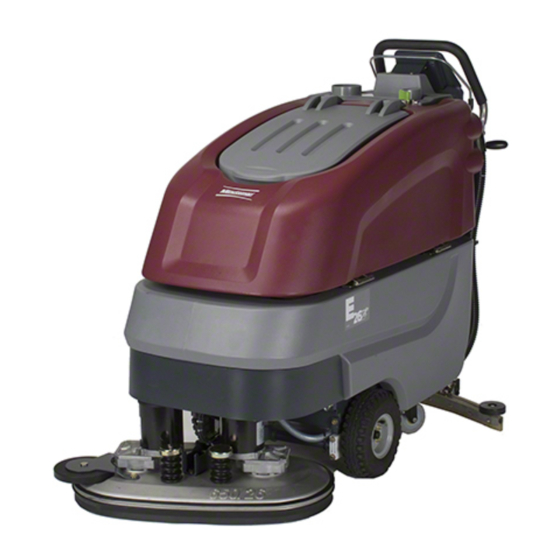
Operation 3 Operation Method of Operation General The E 24 is a vacuum scrubbing machine for wet cleaning of hard-surfaced floors. 3.1.1 Brush Deck Lower brush deck (Fig. 3/1) via pedal before scrubbing. The brushes rotate and solution supply switches on automatically. When the machine is stopped, brushes and solution supply switch off automatically. -
Page 14: Squeegee
Contact your traction drive control realises modification and squeegee blades. The soiled water is Minuteman Dealer for more of travel speed, direction as well as wiped from the floor by means of information. -
Page 15: Operating And Indicating Elements
Operation Operating and Indicating Elements 3.2.1 Operating Panel 1 Display 2 Key switch 3 Battery charge indication 4 LDS indicator 5 Symbol brush drive 6 Symbol vacuum motor 7 Hourmeter 8 Symbol Service indicator 9 free 10 Symbol Silence Kit (optional) 11 Symbol solution flow 12 Tip-switch Silence Kit (optional) 13 Tip-switch solution flow... - Page 16 Operation Display (Fig. 4/1) This panel allows centralized monitoring of 1.1.1.1 functions and detection of all available operating modes. Hourmeter (Fig. 4/7) LDS indicator (Fig. 4/4) Upon switching on, the LDS indication is Upon switching on, the hourmeter briefly displays the software version and the last output on the panel to show the current battery charge condition during operation.
- Page 17 Operation free (Fig. 4/9) Solution flow tip-switch (Fig. 4/ 13) This tip-switch is used to regulate the amount of solution. Additionally, solution amount is adapted to driving speed. The Silence Kit tip symbol (optional) display shows a six-stage symbol for the (Fig.
-
Page 18: At The Machine
Operation 3.2.2 At the machine 1 Brush deck pedal 2 Opening of solution tank 3 Squeegee lift lever 4 Solution filter 5 Recovery tank drain hose 6 Solution level indication 7 Brush ejector 8 Power connection charger unit Fig.5... - Page 19 Operation Power Connection Charger Unit Brush Deck Pedal (Fig. 5/1) (Fig. 5/8) Use this pedal to lift and lower the brush The power connection supplies the deck. charger unit with power. Opening of Solution Tank (Fig. 5/2) The solution tank is filled through the opening under the solution tank cover.
- Page 20 Operation Dirt Hopper Guiding Rail (Fig. 6/1) The dirt hopper located at the cylindrical brush deck is fastened by a guiding rail. This dirt hopper may be easily removed for cleaning. Lever for Cylindrical Brush Seating (Fig. 6/2) This lever (both sides) is used to release/ lock the cylindrical brush seating.
-
Page 21: Technical Data
Technical Data Technical Data Disc brush deck Cylindrical brush deck Machine length 59.5 in (151.1 cm) 62.6 (159 cm) Machine height 43.7 in (111 cm) 43.7 (111 cm) 26.8 in (68.1 cm) 26.8 (68.1 cm) Machine width without Squeegee Machine width with Squeegee 37.5 in (95.3 cm) 37.5 (95.3 cm) Working width... - Page 22 Technical Data Noise emission The sound pressure level measured under maximum conditions of use (LwA) according to DIN EN 60335-2-72 amounts to: dB (A) The sound pressure level measured (at the ear of the driver) under normal conditions of use (LpA) according to DIN EN 60335-2-72 amounts to: dB (A) Measurement inaccuracy (KpA):...
-
Page 23: Maintenance And Care
To be performed by qualified personnel of Please contact your local Minuteman Service determined and listed in spare part kits. authorized Minuteman Service Center in Center or Minuteman contract dealer. We... -
Page 24: Maintenance Document
Maintenance and Care Maintenance document Handing over System Maintenance I System Maintenance II System Maintenance I 125 operating hours 250 operating hours 375 operating hours Upgrade Workshop stamp Workshop stamp Workshop stamp Test drive Handing over to the customer Instruction carried out on: carried out on: carried out on:... -
Page 25: Maintenance Schedule
Maintenance and Care Maintenance Schedule System Maintenance Customer The daily and weekly maintenance intervals must be performed by the customer/operator. In te rv a l T o b e p e rfo rm e d d a ily w e e k ly F ill so lu tio n ta n k a n d p ro ce e d to ch e m ic a l a g e n t d o sa g e C h a rg e b a tte rie s C h e c k b ru s h d e ck a n d cle a n if re q u ire d... - Page 26 Maintenance and Care System Maintenance I The following maintenance work must be performed by an authorized Minuteman Service workshop. Interval To be performed every 125 hours of operation Check battery charger Check tank lid seal of the recovery tank and replace if required...
- Page 27 Maintenance and Care System Maintenance II The following maintenance work must be performed by an authorized Minuteman Service workshop. In te rv a l T o b e p e rfo rm e d e v e ry 2 5 0 h o u rs o f o p e ra tio n...
- Page 28 Maintenance and Care System Maintenance S (Safety check) The following maintenance work must be performed by an authorized Minuteman Service workshop at least once a year. Interval To be perform ed every 500 hours of operation Perform m aintenance w ork according to S ystem M aintenance II...
-
Page 29: Battery Systems
Maintenance and Care Battery Systems 1 LDS display 2 Charger indicator 3 Charger 4 Mains cable charger 5 Battery connector 6 Batteries 7 Recovery tank 8 Support 9 Wiring diagram Fig.7... -
Page 30: Charging Batteries
(ex. from lead acid to gel) the the low discharge signal sender. (Fig. 7/9). Tighten fasteners and grease charger has to be adjusted by a Minuteman poles. contract workshop. 5.4.3 Maintenance of Drive Batteries... -
Page 31: Solution Tank
Maintenance and Care Solution Tank 1 Solution tank 2 Marker 3 Fill level hose 4 Solution filter 5 Tank lid Fig.8... -
Page 32: Filling Solution Tank
Maintenance and Care 5.5.1 Filling Solution Tank 5.5.3 Solution Filter Check solution filter (Fig. 8/4) at weekly Fill solution tank (Fig. 8/1) before work or as required. Park machine on level ground. intervals and clean or replace if required. Open tank lid (Fig. 8/5) and fill tank up to the Only clean solution filter when the maximum (1/1 marker) (Fig. -
Page 33: Recovery Tank
Maintenance and Care Recovery Tank 1 Recovery tank 2 Drain hose 3 Suction filter 4 Tank lid Fig.9... -
Page 34: Emptying Recovery Tank
Maintenance and Care 5.6.2 Cleaning Recovery Tank 5.6.1 Emptying Recovery Tank Clean recovery tank (Fig. 9/1) at daily Clean recovery tank (Fig. 9/1) at daily intervals or as required. intervals, as required or upon acoustic signal 1. Empty recovery tank, see paragraph 5.6.1. (increased vacuum motor speed). -
Page 35: Disc Brush Deck
Maintenance and Care Disc Brush Deck 5.7.2 Changing Brushes 5.7.1 Cleaning Brushes 1 Brush deck lift pedal Check brushes of the brush deck for wearing Clean brushes of the brush deck (Fig. 10/2) 2 Brush deck at daily intervals or as required. at weekly intervals. -
Page 36: Cylindrical Brush Deck
Maintenance and Care 5.8.1 Cleaning Dirt Hopper 5.8.2 Removing Brushes Cylindrical Brush Deck Clean dirt hopper (Fig. 11/2) at daily intervals 1. Raise the cylindrical brush deck (Fig. 11/ 1 Brush deck lift pedal or as required. 3) using pedal (Fig. 11/1). 2 Dirt hopper Remove dirt hopper from the right machine 2. -
Page 37: Squeegee
Maintenance and Care Squeegee 5.9.1 Cleaning the Squeegee 5.9.2 Changing the Squeegee Blades Check the squeegee (Fig. 12/1) daily and Check the inner and outer squeegee 1 Squeegee clean as necessary. To clean it lift the blades on the squeegee (Fig. 12/1) weekly 2 Star-shaped knob squeegee out, pull off the suction hose (Fig. -
Page 38: Adjusting The Squeegee Blades
Maintenance and Care Fig.13... - Page 39 Maintenance and Care Height Adjustment The height adjustment is set to 3 mm at the factory. If streaks are produced, despite an optimum angle adjustment, the clearance between the rollers and floor must be adjusted by changing the number 3 mm of washers on the holder.
-
Page 41: Ec- Declaration Of Conformity
EC-Declaration of Conformity (according to Directive 98/37/EC) Minuteman International Inc. For the relevant implementation of the safety 14N845 U.S. Route 20 and health requirements mentioned in the Pingree Grove, IL 60140 Directives, the following standard (s) and/or U.S.A. technical specification(s) has (have) been... -
Page 42: Warranty
Minuteman will, at its option, repair or replace without charge, parts that fail under normal use and service when operated and maintained in accordance with the applicable operation and instruction manuals. All warranty claims must be submitted through and approved by factory authorized repair stations. - Page 43 If a difficulty develops with this machine, you should contact the dealer from whom it was purchased. This warranty gives you specific legal rights, and you may have other rights which vary from state to state. Some states do not allow the exclusion or limitation of special, incidental or consequential damages, or limitations on how long an implied warranty lasts, so the above exclusions and limitations may not apply to you.
Need help?
Do you have a question about the E24 and is the answer not in the manual?
Questions and answers