Table of Contents
Advertisement
Quick Links
Advertisement
Table of Contents

Related Manuals for JCM TAIKO PUB-7/11


Summary of Contents for JCM TAIKO PUB-7/11
- Page 1 Support: http://www.jcmglobal.com/en/contact/default.aspx Web-Site: http://www.jcmglobal.com Taiko™ Series Banknote Acceptor (PUB-7/11) Operation and Maintenance Manual (Revision 4) P/N 960-100175R_Rev. 4 {EDP #200824} Issue #4045-SME-01-04 © 2013, Japan CashMachine Co., Limited...
- Page 2 2. When an end user duplicates the Manual to maintain operation of the product or operate the product in general. JCM retains all rights to amend, alter, change or delete any portion of this Manual in whole, or in part, or add items ...
-
Page 3: Table Of Contents
Structural Specifications ......................1-7 System Configuration ....................1-7 Unit Dimensions ......................1-8 Taiko PUB-7 Standard Bezel Unit Outside Dimensions ............1-8 Taiko PUB-7/11 Unit Clearance Dimensions ................1-8 Taiko PUB-11 Standard US Bezel Unit Outside Dimensions ............1-9 International Compliance ..................1-10 Technical Contact Information .................1-11 Americas &... - Page 4 Europe, Africa, Russia & Middle East ..................3-1 JCM Europe GmbH ....................... 3-1 UK & Ireland ..........................3-1 JCM Europe (UK Office) ......................3-1 Asia ............................3-1 JCM Gold (HK) Ltd........................ 3-1 Japan Cash Machine Co, Limited (HQ) ................... 3-1 4 DISASSEMBLY/REASSEMBLY ................
- Page 5 No.7 Exit Flapper Test Procedure ....................... 6-9 7 EXPLODED VIEWS AND PARTS LISTS ............7-1 Entire Taiko Unit Exploded View ................7-1 Primary Taiko PUB-7/11 Unit Parts List ..................7-2 Complete Taiko Unit Exploded View ..................7-3 Complete Taiko PUB-7/11 Units Parts List ................7-4 Taiko Bezel Unit Exploded View ................
- Page 6 Taiko™ Series Banknote Acceptor THIS PAGE INTENTIONALLY LEFT BLANK P/N 960-100175R_Rev. 4 {EDP #200824} © 2013, Japan CashMachine Co., Limited...
- Page 7 Figure 1-12 Taiko PUB-7/11 System Configuration ..........1-7 Figure 1-13 Taiko PUB-7 Complete Unit Outside Dimensions........1-8 Figure 1-14 Taiko PUB-7/11 Banknote Acceptor’s Clearance Dimensions ....1-8 Figure 1-15 Taiko PUB-11 (US Dollar) Complete Unit Outside Dimensions ..... 1-9 Figure 2-1 Taiko Bezel Cut-Out Dimensions............
- Page 8 Figure 6-1 Required PUB-7/11 PC Download Workbench Tool ......6-1 Figure 6-2 Required PUB-7/11 Palm Pilot Download Workbench Tool....6-1 Typical Tungsten Series Palm Pilot Handheld with JCM Software Figure 6-3 Icons....................... 6-2 Figure 6-4 Taiko DIP Switch & Port Location ............6-2 Figure 6-5 Taiko PC Download Program Screen ............
- Page 9 Taiko™ Series Banknote Acceptor List of Figures Page Figure 7-3 Taiko PUB-7/11 Bezel Unit Exploded View ..........7-8 Figure 7-4 Taiko PUB-7/11 Bezel Unit Exploded View ..........7-10 P/N 960-100175R_Rev. 4 {EDP #200824} © 2013, Japan CashMachine Co., Limited...
- Page 10 Taiko™ Series Banknote Acceptor THIS PAGE INTENTIONALLY LEFT BLANK P/N 960-100175R_Rev. 4 {EDP #200824} © 2013, Japan CashMachine Co., Limited viii...
- Page 11 Table 6-4 Solenoid Error Codes................6-9 Table 6-5 LED Flash Error Codes ................6-9 Table 7-1 Primary Taiko PUB-7/11 Unit Parts List ........... 7-2 Table 7-2 Complete Taiko PUB-7/11 Units Parts List ..........7-4 Table 7-3 Taiko PUB-7/11 Bezel Units Parts List............. 7-9 Table 7-4 Taiko EBA Type Bezel Units Parts List ..........
- Page 12 Taiko™ Series Banknote Acceptor THIS PAGE INTENTIONALLY LEFT BLANK P/N 960-100175R_Rev. 4 {EDP #200824} © 2013, Japan CashMachine Co., Limited...
-
Page 13: Taiko™ Series
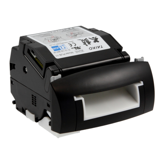
Steps, requiring the operator to perform • Specifications • specific actions are given sequential numbers System Configuration • (1., 2., 3., etc). Taiko PUB-7/11 Unit Figure 1-1 Taiko PUB-7/11 Unit P/N 960-100175R_Rev. 4 {EDP #200824} © 2013, Japan CashMachine Co., Limited 1 - 1... -
Page 14: Model Descriptions
Table 1-1 lists the Product Model Number 1. Do not allow the Unit to endure or operate at a Descriptions. high temperature, in high humidity and/or in a Table 1-1 Taiko PUB-7/11 Model Number dusty environment. Specifications 2. Do not use the Acceptor where temperature vari- ations widely fluctuate. -
Page 15: Banknote Fitness Requirements
• Shabby/warn condition • Adhering foreign objects and/or oil. Damaged Banknotes Figure 1-5 Scan Frequency Capability • This JCM patented Anti-Pullback Mechanism provides powerful protection against Banknote stringing (fishing). The drum rotates every Wrinkled Banknotes time a Banknote passes through the Unit, and... -
Page 16: Product Label
Section 1 Taiko™ Series Banknote Acceptor General Information Product Label Figure 1-9 and Figure 1-10 illustrates the simple installation instructions contained on the Taiko™ top panel label. Figure 1-6 Taiko Anti-Pullback Feature • The Taiko™ Unit can connect to a Palm Pilot ®... -
Page 17: Component Names
LED Display Lens l) DIP Switch Block f) Banknote Insertion Slot m)Bezel Installation Guide Pin g) Banknote Exit Slot Figure 1-11 Taiko PUB-7/11 Component Names P/N 960-100175R_Rev. 4 {EDP #200824} © 2013, Japan CashMachine Co., Limited 1 - 5... -
Page 18: Specifications
†† Front Panel Bezel LED, Full color illuminating (Gradation & Solid) Diagnostic Indicators Escrow: 1 note Anti-stringing Mechanism: Pull-Back (PB) Unit (Anti-pullback system - JCM Patented) ** X4: ID-003 (Serial)/MDB/Pulse/ccTalk Interface: 01: Parallel (ID-001) 03: Serial (ID-003) *. When security measures against counterfeiting are implemented, the software may not fulfill the specified acceptance rate level. -
Page 19: Electrical Specifications
Taiko™ PUB-7/11 Unit b) Palm Pilot Tungsten C c) PC (Windows 98SE/2000/XP) d) JCM Power Supply Unit (EDP# 116125, JAC Part# 501-000187RA) e) Taiko™ Harness B (EDP# 116488, JAC Part# 400-100573RA) f) Taiko™ Harness A (EDP# 121797, JAC Part# 400-100551RA) g) Host Machine (Gaming, Vending, etc.) -
Page 20: Unit Dimensions
7.87 inches Depth Below Unit 3.93 inches (200mm) or more 3.93 inches (100mm) (100mm) or more or more Figure 1-14 Taiko PUB-7/11 Banknote Acceptor’s Clearance Dimensions P/N 960-100175R_Rev. 4 {EDP #200824} © 2013, Japan CashMachine Co., Limited 1 - 8... -
Page 21: Taiko Pub-11 Standard Us Bezel Unit Outside Dimensions
General Information Taiko™ Series Banknote Acceptor Section 1 PUB-11 S US B AIKO TANDARD EZEL UTSIDE IMENSIONS Figure 1-15 illustrates the Taiko™ PUB-11 Type 5 Standard US Bezel Unit outside dimensions. 51 (Banknote Top Side Ejection Position) (Panel Thickness) Door Installation Position (Maximum Banknote Width 66) Right Side... -
Page 22: International Compliance
Section 1 Taiko™ Series Banknote Acceptor General Information International Compliance RoHS Directives • UL & c-UL Marks E142330, Subscriber 857947001, Vol. 2 • CE Mark • P/N 960-100175R_Rev. 4 {EDP #200824} © 2013, Japan CashMachine Co., Limited 1 - 1 0... -
Page 23: Technical Contact Information
Technical Contact Information To obtain further Technical Information regarding the Taiko™ PUB-7/11 Device, please contact the clos- est office to your location listed below: & O CEANIA MERICAS JCM Gold (HK) Ltd. JCM American Phone: +852-2429-7187 Phone: +1-702-651-0000 Fax: +852-2929-7003 Fax: +1-702-644-5512 Unit 1-7, 3/F., Favor Industrial Centre... - Page 24 Section 1 Taiko™ Series Banknote Acceptor General Information THIS PAGE INTENTIONALLY LEFT BLANK P/N 960-100175R_Rev. 4 {EDP #200824} © 2013, Japan CashMachine Co., Limited 1 - 1 2...
-
Page 25: Installation
Taiko™ Series Banknote Acceptor S e c t i o n 2 2 INSTALLATION This section provides installation/operation • Connector Pin Assignments instructions for the Taiko Banknote Acceptor ™ • Preventive Maintenance Series (PUB-7/11). This section contains the •... -
Page 26: Power Harness Wiring Procedure
Section 2 Taiko™ Series Banknote Acceptor Installation NOTE: DIP Switch settings may vary based on Bezel Brackets Software changes related to the specific Country using the Taiko Unit. Table 2-1 Power Connector Specifications Hexagonal Nuts Connector Part Lock Lever Socket Ribbon Cable Socket XG5M-1032-N XG4M-1030-T... -
Page 27: Clearing A Lower Area Banknote Jam
Installation Taiko™ Series Banknote Acceptor Section 2 DIP Switch Configurations 2. Press-in on the Upper Lid Open/Close Buttons and open the Upper Lid in the direction indicated The communication method and various Taiko™ in Figure 2-9 . Unit functions can be selected by using the Unit’s 3. -
Page 28: Denomination Setting Mode
Section 2 Taiko™ Series Banknote Acceptor Installation 2. Set DIP Switch No.1, No. 6 and No.7 to Table 2-3 Programming DIP Switch Settings (See Figure 2-13). 3. Re-apply Power to the Taiko™ Unit. 4. After the Front Panel LED display flashes White, set DIP Switch No.1 to the position to enter the Setting Mode. -
Page 29: Encryption Code Initialization Setting Mode
Installation Taiko™ Series Banknote Acceptor Section 2 Encryption Code Initialization Setting Table 2-5 Serial ID-003/MDB Interface Pin Mode Assignments When using the ccTalk Communication Mode (e.g., Signal The Encryption Mode) and the Encryption Code is Pin No. Function Name unknown, set the Encryption Code Initialization No Connection Setting to start the Encryption Code in order to No Connection... -
Page 30: Cleaning Procedures
Taiko™ Series Banknote Acceptor Installation Available Cleaning Card Table 2-8 Parallel ID-001 Interface Pin Assignments A JCM Waffletechnology Bill Validator Cleaning Card is now available (JCM Part No. 501-000252R, Signal Pin No. Function Name Manufacturer’s Part No. KWJCM-B5B15M). The +12V DC Power... -
Page 31: Taiko Sensor And Roller Locations
Installation Taiko™ Series Banknote Acceptor Section 2 Taiko Sensor and Roller Locations Figure 2-21 illustrated the various Taiko Sensor cleaning locations, and Table 2-9 respectively lists the Taiko Sensor Type Cleaning Methods. Dummy Head Magnetic Head Roller Figure 2-21 Taiko Sensor Cleaning Locations Table 2-9 Taiko Sensor Type Cleaning Methods Sym. - Page 32 Section 2 Taiko™ Series Banknote Acceptor Installation THIS PAGE INTENTIONALLY LEFT BLANK P/N 960-100175R_Rev. 4 {EDP #200824} © 2013, Japan CashMachine Co., Limited 2 - 8...
-
Page 39: Operational Flowcharts
Installation Taiko™ Series Banknote Acceptor Section 2 Operational Flowcharts Figure 2-27 depicts part one of a typical Taiko™ Initialization Banknote acceptance flow process. Apply Power to the Unit. a) Initializing B) Return from Figure 2-28 b) Stand-by c) Is the Banknote accepted? d) External LED distinguish e) External LED lights f) Is the Banknote inserted? -
Page 40: Operational Flowcharts (Continued)
Section 2 Taiko™ Series Banknote Acceptor Installation Operational Flowcharts (Continued) Figure 2-28 depicts part two of a typical Taiko™ Banknote acceptance flow process. A) From “Part 1” (See Figure 2-27) a) Transport the Banknote out (Carry the Banknote to the Cash Box) b) Has the Banknote transported? c) Retried carrying the Banknote out d) Has the Banknote transported? -
Page 41: Communications
3 COMMUNICATIONS This section was intentionally left out due to a Non-Disclosure Agreement requirement. If this information is required, please contact the closest office location listed below: Americas Asia & Oceania JCM A JCM G (HK) L MERICAN Phone: +1-702-651-0000... - Page 42 Section 3 Banknote Acceptor Communications THIS PAGE INTENTIONALLY LEFT BLANK P/N 960-100175R_Rev. 4 {EDP #200824} © 2013, Japan CashMachine Co., Limited 3 - 2...
-
Page 43: Disassembly/Reassembly
Taiko™ Series Banknote Acceptor S e c t i o n 4 4 DISASSEMBLY/REASSEMBLY CPU Circuit Board Removal This section provides disassembly and reassembly instructions for the Taiko PUB-7/11 Banknote To remove the CPU Circuit Board, proceed as ™ Acceptor Series. -
Page 44: Mag Board Removal (Pub-11 Only)
Section 4 Taiko™ Series Banknote Acceptor Disassembly/Reassembly MAG Board Removal (PUB-11 Only) The MAG Circuit Board is mounted in a PUB-11 Unit only below the CPU Circuit Board. To remove the MAG Circuit Board, proceed as follows: 1. Remove the Harness Connector and remove the CPU Circuit Board as previously described dur- ing “CPU Circuit Board Removal”... -
Page 45: Encoder Board And Drive Motor Removal
Disassembly/Reassembly Taiko™ Series Banknote Acceptor Section 4 Figure 4-8 Taiko Transport Drum Removal Figure 4-11 Transport Drum Separation 9. Remove the single (1) Prism Mounting Screw (See Figure 4-12 a) and remove the Prism (See Figure 4-12 b) from the Upper Center Guide Assembly (See Figure 4-12 c). -
Page 46: Entrance And Exit Solenoid Removal
Section 4 Taiko™ Series Banknote Acceptor Disassembly/Reassembly 2. Remove the single (1) Motor Drive Assembly mounting screw (See Figure 4-14 a) from the Lower Center Guide (See Figure 4-14 b). 3. Remove the Motor Drive Assembly (See Figure 4-14 c) from the Lower Center Guide Section. Figure 4-16 Lower Guide Assembly Removal Figure 4-14 Motor Drive Assembly Removal 4. -
Page 47: Figure 4-19 Entrance & Exit Solenoid Removal
Disassembly/Reassembly Taiko™ Series Banknote Acceptor Section 4 Figure 4-19 Entrance & Exit Solenoid Removal The Taiko™ Disassembly Procedure is now com- plete. Reverse all or part of the preceding instruc- tions to reassemble any of the components described during this disassembly procedure. P/N 960-100175R_Rev. - Page 48 Section 4 Taiko™ Series Banknote Acceptor Disassembly/Reassembly THIS PAGE INTENTIONALLY LEFT BLANK P/N 960-100175R_Rev. 4 {EDP #200824} © 2013, Japan CashMachine Co., Limited 4 - 6...
-
Page 49: Wiring Diagrams
Taiko™ Series Banknote Acceptor S e c t i o n 5 5 WIRING DIAGRAMS This Section provides the Taiko Banknote Accep- • PUB-7 System Wiring Diagrams ™ tor Series (PUB-7/11) Wiring Diagrams and inter- • PUB-11 System Wiring Diagrams. connect information for the following items: PUB-7 System Wiring Diagrams Figure 5-1 PUB-7 12 Volt DC System Wiring Diagram... -
Page 50: Pub-7 System Wiring Diagrams (Continued)
Section 5 Taiko™ Series Banknote Acceptor Wiring Diagrams PUB-7 System Wiring Diagrams (Continued) Figure 5-2 PUB-7 24 Volt DC System Wiring Diagram P/N 960-100175R_Rev. 4 {EDP #200824} © 2013, Japan CashMachine Co., Limited 5 - 2... -
Page 51: Pub-11 System Wiring Diagrams
Wiring Diagrams Taiko™ Series Banknote Acceptor Section 5 PUB-11 System Wiring Diagrams Figure 5-3 PUB-11 12 Volt DC System Wiring Diagram (with Mag) P/N 960-100175R_Rev. 4 {EDP #200824} © 2013, Japan CashMachine Co., Limited 5 - 3... -
Page 52: Pub-11 System Wiring Diagrams (Continued)
Section 5 Taiko™ Series Banknote Acceptor Wiring Diagrams PUB-11 System Wiring Diagrams (Continued) Figure 5-4 PUB-11 24 Volt DC System Wiring Diagram (with Mag) P/N 960-100175R_Rev. 4 {EDP #200824} © 2013, Japan CashMachine Co., Limited 5 - 4... -
Page 53: Calibration And Testing
• A Palm Pilot ® Handheld PDA - Tungsten • Calibration Procedure Series C Version (Figure 6-3 showing JCM • Performance Tests. Software a, b & c Hot Sync Cradle or Cable) Workbench Tool Requirements ® NOTE: Refer to the Palm Pilot or the VM-450 •... -
Page 54: Software Download Preparation
Palm Flash Program c) PSP-02 Program b) PalmA66US Program Figure 6-3 Typical Tungsten Series Palm Pilot Handheld with JCM Software Icons WARNING: Make sure the External Figure 6-5 Taiko PC Download Program Screen Power Supply is OFF when connecting 4. -
Page 55: Writing A New Serial Number
® to be transferred into the Palm Pilot • PC (OS: Windows ® 98 SE/2000/XP) memory first. • JCM Taiko™ Banknote Acceptor (PUB-7 or “ ” and the ID003DWN.prc PUB-11) file previously created during Step 4d. .pdb • Downloader Application (Download Program ®... -
Page 56: Figure 6-8 Taiko Re-Programming Software Tool Connection Configuration
† White ID-001 *. Use JCM Power Supply Unit (EDP# 116125, JAC# 501-000187RA) or equivalent. Or use Taiko™ Harness “A” (EDP# 127527, JAC# 400- 100551RA or JCME G00183 for ID-003 & G00182 for ID-0E3). †. Use JCM Power Supply Unit (EDP# 059307, JAC# 400-100643RA) or equivalent VM-450 Harness (EDP# 139571, JAC# 400- 100643RA). -
Page 57: Re-Programming Connection Procedure
Taiko™ Harness “A” are not required. Current Serial Number LONING ROCEDURES Perform the following steps to Clone a Taiko™ Figure 6-9 JCM Serial Number Writer Screen Unit: 3. Mouse-Click on the Screen Read Serial Number 1. Connect the Master Taiko™ Unit, the Slave Button (See Figure 6-9 a) and the current Unit’s... -
Page 58: Figure 6-10 Taiko Clone Software Tool Connection Configuration
Taiko™ Harness “B” c) VM-450 Supply Unit (EDP# 116488, JAC# 400-100573RA (EDP# 059307, JAC# 501-000026RA) or JCME G00172) d) JCM Power Supply Unit h) Taiko™ Harness “A” (EDP# 116125, JAC# 501-000187RA (EDP# 127527, JAC# 400-100551RA or JCME G00176 & G00205) or Equivalent or JCME G00183 for ID-003 &... -
Page 59: Calibration Procedures
Workbench. Calibration Tool Requirements The following equipment and tools are required to perform Taiko™ Workbench calibration: • JCM Taiko™ Banknote Acceptor (PUB-7 or PUB-11) • JCM External Power Supply (EDP# 116125, Figure 6-13 Reference Paper Insertion JAC# 501-000187RA) or equivalent 7. -
Page 60: Dip Switch Tests
Section 6 Taiko™ Series Banknote Acceptor Calibration and Testing In order to identify a failure condition’s cause, the No.2 Transport Motor Reverse Rotation Test Taiko™ Unit has to be in the TEST Mode. This Test detects the Taiko™ Unit’s reverse Motor speed rotational rate. -
Page 61: No.4 Solenoid Test Procedure
Calibration and Testing Taiko™ Series Banknote Acceptor Section 6 Table 6-3 Aging Test Error Codes (Cont.) Table 6-5 LED Flash Error Codes (Cont.) Flash No. Red Flashes Error Indicated Sensor Location & Color Motor Error Right Red Transmissive (Upper to Lower) Entrance Solenoid Error Left Red Transmissive (Upper to Lower) Exit Solenoid Error... - Page 62 Section 6 Taiko™ Series Banknote Acceptor Calibration and Testing THIS PAGE INTENTIONALLY LEFT BLANK P/N 960-100175R_Rev. 4 {EDP #200824} © 2013, Japan CashMachine Co., Limited 6 - 1 0...
-
Page 63: Exploded Views And Parts Lists
Taiko™ Series Banknote Acceptor S e c t i o n 7 7 EXPLODED VIEWS AND PARTS LISTS This section provides product exploded views and • Primary Taiko Unit Exploded View parts lists for the Taiko Banknote Acceptor ™ • Complete Taiko Unit Exploded View (PUB-7/11 ®... -
Page 64: Primary Taiko Pub-7/11 Unit Parts List
Section 7 Taiko™ Series Banknote Acceptor Exploded Views and Parts Lists Primary Taiko PUB-7/11 Unit Parts List Table 7-1 Primary Taiko PUB-7/11 Unit Parts List Ref No. EDP No. JAC Part No. Description Remark PUB-7 Unit (See Figure 7-2 for individual parts) -
Page 65: Complete Taiko Unit Exploded View
Exploded Views and Parts Lists Taiko™ Series Banknote Acceptor Section 7 Complete Taiko Unit Exploded View Figure 7-2 Complete Taiko PUB-7/11 Unit Exploded View P/N 960-100175R_Rev. 4 {EDP #200824} © 2013, Japan CashMachine Co., Limited 7 - 3... -
Page 66: Complete Taiko Pub-7/11 Units Parts List
Section 7 Taiko™ Series Banknote Acceptor Exploded Views and Parts Lists Complete Taiko PUB-7/11 Units Parts List Table 7-2 Complete Taiko PUB-7/11 Units Parts List Ref No. EDP No. JAC Part No. Description Remark 115543 451-100102RA Entrance Solenoid 115544 451-100103RA... - Page 67 Exploded Views and Parts Lists Taiko™ Series Banknote Acceptor Section 7 Table 7-2 Complete Taiko PUB-7/11 Units Parts List (Continued) Ref No. EDP No. JAC Part No. Description Remark 110889 900-101008RA Lower Guide Cover 110890 250-100557RA Spring Guide 110892 900-101009RA...
- Page 68 Section 7 Taiko™ Series Banknote Acceptor Exploded Views and Parts Lists Table 7-2 Complete Taiko PUB-7/11 Units Parts List (Continued) Ref No. EDP No. JAC Part No. Description Remark Used in PUB EDP 109360 300-100422RA CPU Board, Pub-7, TWN/GBR/SCO...
- Page 69 Exploded Views and Parts Lists Taiko™ Series Banknote Acceptor Section 7 Table 7-2 Complete Taiko PUB-7/11 Units Parts List (Continued) Ref No. EDP No. JAC Part No. Description Remark For use only in PUB-11 130880 300-200130RA Magnetic (MAG) Sensor Board NOT operating at 12/24V VC/MS Conversion Sensor Board ...
-
Page 70: Taiko Bezel Unit Exploded View
Section 7 Taiko™ Series Banknote Acceptor Exploded Views and Parts Lists Taiko Bezel Unit Exploded View Figure 7-3 Taiko PUB-7/11 Bezel Unit Exploded View P/N 960-100175R_Rev. 4 {EDP #200824} © 2013, Japan CashMachine Co., Limited 7 - 8... -
Page 71: Taiko Pub-7/11 Bezel Units Parts List
Exploded Views and Parts Lists Taiko™ Series Banknote Acceptor Section 7 Taiko PUB-7/11 Bezel Units Parts List Table 7-3 Taiko PUB-7/11 Bezel Units Parts List Ref No. EDP No. JAC Part No. Description Remark 110884 200-200384RA Bezel 110897 900-100981RA PUB-7 Bezel Guide for EURO (68mm) -
Page 72: Taiko Eba Type Bezel Unit Exploded View
Section 7 Taiko™ Series Banknote Acceptor Exploded Views and Parts Lists Taiko EBA Type Bezel Unit Exploded View Figure 7-4 Taiko EBA Type Bezel Unit Exploded View P/N 960-100175R_Rev. 4 {EDP #200824} © 2013, Japan CashMachine Co., Limited 7 - 1 0... -
Page 73: Taiko Eba Type Bezel Units Parts List
Exploded Views and Parts Lists Taiko™ Series Banknote Acceptor Section 7 Taiko EBA Type Bezel Units Parts List Table 7-4 Taiko EBA Type Bezel Units Parts List Ref No. EDP No. JAC Part No. Description Remark 127556 Face Fix Hook 187815 EBA Type Bezel A 187817... - Page 74 Section 7 Taiko™ Series Banknote Acceptor Exploded Views and Parts Lists THIS PAGE INTENTIONALLY LEFT BLANK P/N 960-100175R_Rev. 4 {EDP #200824} © 2013, Japan CashMachine Co., Limited 7 - 1 2...
-
Page 75: Index
… definitions of Exploded View System Wiring Diagram … illustrations of … Schematic diagram of External Power Supply … Part No. for Taiko PUB-7/11 Unit … photo of a Flowchart Tool Requirements Operational … … workbench 2-15 2-16 symbol language describing flow functions Troubleshooting …... - Page 76 Taiko™ Series Banknote Acceptor Index Index THIS PAGE INTENTIONALLY LEFT BLANK © 2013, Japan CashMachine Co., Limited P/N 960-100175R_Rev. 4 {EDP #200824} 8 - 2...
-
Page 77: A Troubleshooting
Taiko™ Series Banknote Acceptor A p p e n d i x A A TROUBLESHOOTING This section provides Troubleshooting instructions causes and the possible fault area. If the Validator for the Taiko Banknote Acceptor (PUB-7/11) Head has to be repaired by disassembling it, ™... - Page 78 The Software program for the specified in the specific Country’s Software Information Sheet (See Banknote inserted is not Table 1-2, “Taiko PUB-7/11 Technical Specification,” on page 1-6 of supported Section 1 in this Service Manual). The Loaded Software does not...
- Page 79 TroubleShooting Taiko™ Series Banknote Acceptor Appendix A Table A-2 Adjustment Fault Conditions Symptoms/Error Possible Fault Causes Corrective Action Required Messages Use the correct KS-070 or KS-88 specified Reference Paper for Wrong Reference Paper being calibrating the Taiko Unit. used Replace the CPU Circuit Board (See "CPU Circuit Board Removal" Adjustment Error procedure in Section 4 of this Service Manual).
-
Page 80: Error Codes And Conditions
Appendix A Taiko™ Series Banknote Acceptor TroubleShooting Table A-5 Taiko Usage Specifications (Part 2) → EDP No. 109360 137778 148060 136375 189025 900776 130880 189072 189071 195055 131072 189305 Function Board VC/MS VC/MS Board Board Ø2x14 Barcode Power Early Board Board Board Parallel... -
Page 81: B Glossary
Unit … See Page 1-6 Bezel – The Banknote input Bezel portion of a Taiko PUB-7/11 Unit … See Page 2-1 DIP Switch – acronym for a Dual In-line Package Switch - a Printed Circuit Board mountable ... - Page 82 Test Site … See Page 1-1 15 Setting Mode – various selectable Modes available for setting specific operational conditions in the Taiko PUB-7/11 Unit … See Page 2-4 P/N 960-100175R_Rev. 4 {EDP #200824} © 2013, Japan CashMachine Co., Limited...
- Page 83 Taiko™ Series Banknote Acceptor P/N 960-100175R_Rev. 4 {EDP #200824} © 2013, Japan CashMachine Co., Limited...
- Page 84 Taiko™ Series Banknote Acceptor Support: http://www.jcmglobal.com/en/contact/default.aspx Web-Site: http://www.jcmglobal.com Issue #4045-SME-01-04 P/N 960-100175R_Rev. 4 {EDP #200824} © 2013, Japan CashMachine Co., Limited...
Need help?
Do you have a question about the TAIKO PUB-7/11 and is the answer not in the manual?
Questions and answers