Table of Contents
Advertisement
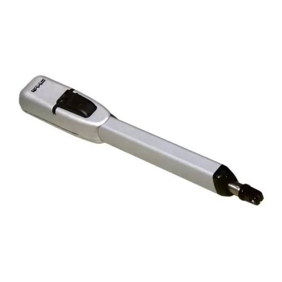
415 L LS 24V
UL325 - UL991
FAAC International Inc.
Headquarter & East Coast Operations
5151 Sunbeam Road
Suites 9-11
Jacksonville, FL 32257
Tel. 866 925 3222
www.faacusa.com
Swing Gate Operator
FAAC International Inc.
West Coast Operations
357 South Acacia Avenue
Unit 357
Fullerton, CA 92831
Tel. 800 221 8278
Advertisement
Table of Contents

Related Manuals for FAAC 415 L LS 24V


Summary of Contents for FAAC 415 L LS 24V
- Page 1 415 L LS 24V Swing Gate Operator UL325 - UL991 FAAC International Inc. FAAC International Inc. Headquarter & East Coast Operations West Coast Operations 5151 Sunbeam Road 357 South Acacia Avenue Suites 9-11 Unit 357 Jacksonville, FL 32257 Fullerton, CA 92831 Tel.
-
Page 2: Table Of Contents
= Information regarding personal safety and proper maintanence of the product. FAAC Model 415 L LS 24V - Rev: 02 - JUN 2012 FA A C M o d el 4 15 L L S 24V S w i n g G at e O p e r a t o r... -
Page 3: Important Safety Information
• Use only FAAC “Photobeam” photoelectric eyes to comply with UL325. FA A C M od e l 41 5 L L S 24V S w ing G ate Oper a tor... -
Page 4: General Safety Precautions
• Install devices such as reversing edges and photo • Use only FAAC MSE MO, CN60 or M60 edge beams to provide better protection for personal sensors. property and pedestrians. Install reversing devices that are appropriate to the gate design and application. -
Page 5: Ul325 Gate Operator Classifications
Installing the Warning Signs This FAAC swing gate operator is supplied with two warning signs to alert people that a possible hazard exists and that appropriate actions should be taken to avoid the hazard or to reduce exposure to it. -
Page 6: Description
The 415 Operator automated system was designed and built for controlling vehicle access. Avoid any other use what so ever. The FAAC 415 is an automatic gate operator for swinging gate leafs. The 415 Operator is useful in residential applica- NOTES: tions and can accommodate gate leafs up to 14 ft long. -
Page 7: Technical Specifications
TECHNICAL SPECIFICATIONS 4.2 Preliminary Checks The condition of the gate structure directly affects the reliabil- SPECIFICATION 415 L LS 24V ity and safety of the automated system. Before installing the Power Supply 24 VDC 415 Operator, prepare the gate for the operator by performing... -
Page 8: Installing The Operator
Guidelines for Determining Installation Dimensions • For 90° leaf openings: A+B=L • For leaf openings exceeding 90°: A+B<L • Smaller A and B dimensions provide higher periph- eral leaf speed. • Limit the difference between A and B dimensions to less than 1.5 inches. -
Page 9: Wiring The Operator
Fig. 9 Turn the rod one half revolution clockwise (Fig. 9, Ref. 2). Assemble the front bracket as shown in Fig. 10. Fix the operator to the rear bracket by means of the sup- plied pins as shown in Fig. 11. Fig. -
Page 10: Adjusting The Limit Switches
• Close and secure the cover with the four supplied screws (Fig. 17). Fig. 14 Figure 14 Table 415 (24 VDC) Fig. 17 POS. COLOR DESCRIPTION White Motor Lead 1 4.6 Adjusting the Limit Switches Not used Note: Limit switches are triggered during the first and the last 1.25 inches of travel. -
Page 11: Start-Up
Fig.21, Ref. 3. Open and close the leaf manually. For any repairs, contact an authorized FAAC repair center. Fig. 21 Ref. 1 FA A C M od e l 41 5 L L S 24V S w ing G ate Oper a tor... -
Page 12: 415 L Ls Parts Diagram
REAR FORK 60202215 GEAR (motor) 716148 UPPER BODY 60202205 24V MOTOR 428403 MANUAL RELEASE ASSEMBLY 709324 GASKET Code 415 L LS 24V Start Date 1/1/1900 60202145 MANUAL RELEASE CAM 60202175 ELECTRIC CABLE COVER 1/1/9999 End Date Description ELECTRO-MECHANICAL 60202155 MANUAL RELEASE LEVER... - Page 13 E024U CONTROL BOARD DESCRIPTION & CHARACTERISTICS SETTING DL14 DL15 DL16 DL17 DL18 DL19 DL20 DL21 DL22 Fig. A1 1.1 TECHNICAL SPECIFICATIONS 1.2 LAYOUT AND COMPONENTS Main power supply RADIO 115/230 V~ 50/60 Hz switchable Connector for the radio receiver Secondary power BATTERY 24 Vdc - 16 A max.
- Page 14 INPUT / OUTPUT DESCRIPTION B STP CL OP OPEN Fig. A2 LABEL FUNCTION 2 EASY 2 EASY Input for bus 2easy accessories (encoder) OPEN A N.O. Contact for total opening command OPEN B / OPEN B: N.O. Contact for opening of leaf 1 only CLOSE (with only one leaf the opening stops at 50% of traveling) CLOSE (LOGIC B-C): N.O.
- Page 15 PHOTOCELLS CONNECTIONS How to connect Normally Open contacts. How to connect Normally Close contacts. (Connect them in parallel) (Connect them in series) Fig. A3 Fig. A4 The E024U board allows the connection of several safety devices (for example photocells). With photocells you can activate the FAILSAFE function, which, before each movement of the ope- rator, tests each fotocells.
- Page 16 Connection of two pairs of closing photocells STP CL OP Other optional safety devices to connect in series RX= Photocell Receiver TX= Ptotocell Transmitter CL= Closing OP= Opening To use the FAIL-SAFE mode connect the negative power supply of the transmitters to OUT (pin 9), and set dip-switch 11 and 12 to ON on DS1 When using the FAIL-SAFE mode also the safety inputs not used (FSW CL , FSW OP) must be connected Fig.
- Page 17 Connection of a pair of closing photocells and a pair of opening photocells STP CL OP RX= Photocell Receiver TX= Ptotocell Transmitter CL= Closing OP= Opening To use the FAIL-SAFE mode connect the negative power supply of the transmitters to OUT (pin 9), and set dip- switch 11 and 12 to ON on DS1 Fig.
-
Page 18: Operating Logic
PROGRAMMING 4.1 DIP SWITCH DS1 SETTINGS FOR OPERATING LOGIC OPERATING LOGIC DS 1: SW 1 - SW 2 - SW 3 PAUSE LOGIC DESCRIPTION TIME E (default) One command opens, the next one closes. A command du- OFF OFF OFF ring opening stops the gate Semiautomatic 0 - 4... - Page 19 4.2 ADJUSTING TRIMMERS – FORCE ADJUSTMENT MOTOR 1 Turn clockwise to increase the opening and closing force TR 2 – FORCE ADJUSTEMENT MOTOR 2 Turn clockwise to increase the opening and closing force TR 3 – SPEED ADJUSTMENT FOR MOTOR1 AND MOTOR 2 Turn clockwise to increase the opening and closing speed TR 4 –...
- Page 20 4.3 DIP SWITCH DS1 SETTINGS FOR BOARD SETUP BOARD SETUP DS 1: SW 4 to SW 12 The opening of leaf 2 is delayed after the opening of leaf 1. This is to avoid OPENING DELAY SW 4 that the gate’s leafs interfere with each other during the initial part of the 0 sec (default) movement.
- Page 21 4.4 DIP SWITCH DS2 SETTINGS FOR OPERATOR TYPE AND LOCK MODE SETTING DL 1 DL 2 DL 3 DL 4 DL 5 IMPORTANT DS 2 DS 2 OPERATOR SELECTION LOCK OUTPUT MODE OPERATOR TYPE SW 1 SW 2 SW 3 OUTPUT MODE SW 4 S450H, S800H...
- Page 22 LED STATUS In BOLD the normal state with gate closed and working DESCRIPTION ON STEADY BLINKING Board working on AC Board working on LED BATTERY power battery power or ext Battery charging supply LED +24 Main power present Main power OFF SLOW BLINK (1 sec.
- Page 23 The diagnostic LED shows only one error condition at a time, with the priority of the below table. In case there is more than one error once one is eliminated the LED will show the next LED ERROR DISPLAY NUMBER OF ERROR CONDITION SOLUTION FLASHES...
- Page 24 AC connection At the point where you want the slowdown to start give an Power outlet OPEN A command with the push button or the remote that Power Supply is already stored in memory. Leaf 2 starts to slow down and and switch stops when it reaches the mechanical stop or FCA2.
- Page 25 The E024U board is powered by a high efficiency switching power supply that takes 115V or 230V in input and provides 36VDC to power the board. The power supply is preset for 115V at the fac- tory, consult with FAAC Tecnical Support for 230V wiring options. 115V 230V...
- Page 26 10. FIRMWARE UPGRADE For the upgrade you need a USB Flash Drive, where you have to copy the file supplied by FAAC. Then follow these steps: The E024U board keeps the operating firmware in a field pro- grammable memory, it can be easily upgraded through the on Disconnect the batteries if they are present.
- Page 27 LOGIC “S” PULSES SYSTEM STATUS OPEN A OPEN B CLOSE STOP FSW OP FSW CL FSW CL/OP opens released no effect no effect opens and closes no effect CLOSED leaf and closes no effect (OPEN disa- (OPEN disa- no effect after pause time (OPEN disabled) after pause time...
- Page 28 LOGIC “SP” PULSES SYSTEM STATUS OPEN A OPEN B CLOSE STOP FSW OP FSW CL FSW CL/OP opens and clo- opens leaf 1 and no effect no effect no effect CLOSED ses after pause closes after pause no effect (OPEN disa- no effect (OPEN disa- (OPEN disabled)
-
Page 29: Limited Warranty
FAAC S.p.A. intended provided it has been properly installed or FAAC International, Inc. The warranty herein and operated.
Need help?
Do you have a question about the 415 L LS 24V and is the answer not in the manual?
Questions and answers