FAAC 415 Manual
Electromechanical swing gate operator
Hide thumbs
Also See for 415:
- Manual (44 pages) ,
- Installation manual (19 pages) ,
- User manual (8 pages)
Table of Contents
Advertisement
Quick Links
Advertisement
Table of Contents

Related Manuals for FAAC 415


Summary of Contents for FAAC 415
- Page 1 115Vac 115Vac Electromechanical Swing Gate Operator FAAC International Inc. FAAC International Inc. Headquarter & East Coast Operations West Coast Operations 3160 Murrell Road 357 South Acacia Avenue Rockledge, FL 32955 Fullerton, CA 92831 Tel. 800 221 8278 www.faacusa.com...
-
Page 2: Table Of Contents
2. Technical Specifications UL325 Gate Operator Classifications 3. Features Installing the Warning Signs 4. Layout and Components 5. Electric Connections 415 OPERATOR 6. Connection of Safety Devices 11. DESCRIPTION & SPECIFICATIONS 7. Operating Logics 1.1 Technical Specifications 8. Programming 1.2 Dimensions 9. -
Page 3: Important Safety Information
Guarding is supplied for exposed rollers. IMPORTANT SAFETY INFORMATION The operator instructions shall list the maximum number of open and close entrapment protection devices capable of being connected to the operator. WARNING - to reduce the risk of severe injury or death: b) The operator is intended for installation only on gates used READ AND FOLLOW ALL INSTRUCTIONS. -
Page 4: General Safety Precautions
GENERAL SAFETY PRECAUTIONS For gate operators that utilize a contact sensor (edge sensor or similar): One or more contact sensors shall be located where Gate Construction the risk of entrapment or obstruction exists, such as at Vehicular gates should be constructed and installed in the leading edge, trailing edge, and postmounted both accordance with ASTM F2200: Standard Specification for inside and outside of a vehicular horizontal slide gate. -
Page 5: Ul325 Gate Operator Classifications
Installing the Warning Signs This FAAC swing gate operator is supplied with two warning signs to alert people that a possible hazard exists and that appropriate actions should be taken to avoid the hazard or to reduce exposure to it. -
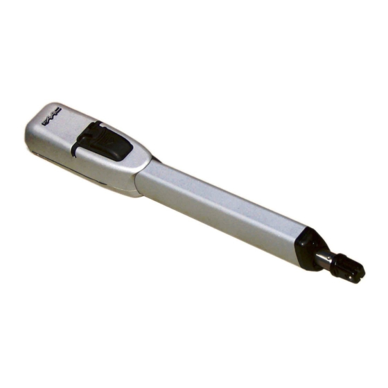
Page 6: 415 Operator
It is designed for residential applications and can ac- commodate gate leafs up to 15 ft long. The self-contained 415 operator consists of an electric motor that drives a worm screw housed in an aluminum casing. The operator has built in limit switches, that can be used in place of positive stops to limt the gate travel. -
Page 7: Installation
Therefore select A and B dimensions that utilize moving parts. the entire operator travel. Short travel ranges can restrict or Positive stops are not needed with the 415 operator, the built cancel the limit switch adjustment range. limit switches can be used to limit the rod travel. - Page 8 Fig. 9 8. Mount the operator to the rear bracket using the supplied pin as shown in Fig. 11. Warning: allow the bracket to cool down before fastening the operator to it. 9. Close the leaf and, while keeping the operator perfectly horizontal, determine the fastening point of the front bracket (Fig.12).
-
Page 9: Wiring The Operator
11. Disengage the operator’s manual release and check Limit Switches wiring instructions: that the gate opens and closes smoothly, without extra Limit switches are wired in the same terminal block where friction or resistance. Ensure that it opens and closes the motor wiring has been installed. -
Page 10: Adjusting The Limit Switches
455D control board section of the manual is different for the remove the cap, Fig.18 Ref.2. 415 operator, due to the presence of the limit switches. Read below for the specific instructions. Learning with limit-switches can be done in two different ways: SIMPLE LEARNING (without slow-down): Check that the leaves are closed, enter "BASIC PROGRAM-... -
Page 11: Manual Operation
Repairs 3. MANUAL OPERATION For repairs, refer to FAAC authorized service centers. If the gate needs to be moved manually due to power outage or an operator malfunction, proceed as follows: Turn power off at the main breaker (even in the event of a power outage). -
Page 12: 455D Control Board
Semi-automatic B / Dead-man C Opening/Closing Time: Connector J2 - Rapid Connection to RP Receivers Programmable (from 0 to 120 s) The 5 pin J2 connector allows to plug in the FAAC RP radio Pause Time: receivers Programmable (from 0 to 4 min.) Closing Leaf Delay: Programmable (from 0 to 4 min.) -
Page 13: Electric Connections
5. Electric Connections VAC MAX. 24 V DC 230 VAC LIMIT-SWITCHES 115 VAC 60 Hz For connection OPEN A of the safety 12 V AC devices, see the OPEN B Maglock next paragraph STOP Note: Capacitors are supplied with the operator or the prewired enclosure OP FSW - Opening safety devices contact (N.C.): Terminal Block J4 - Motors and Warning Lamp The opening safety input is used to protect the leaf move-... -
Page 14: Connection Of Safety Devices
To comply with the UL325 standard for gate operators every entrapment zone, as defined in ASTMF2200, must be pro- ADVANCED PROGRAMMING tected by two independent entrapment protection devices. One of the devices is inherent in the FAAC operators or the Display Function Default control board design, the other can be external, like a pho- tocell or an edge sensor. - Page 15 Only one monitored photocell can be connected to the See the following connections diagrams for example of Closing or Opening safety inputs. More than one photocell opening/closing safety wiring. or other device can be connected to the safety inputs, but they will not be monitored.
-
Page 16: Operating Logics
7. Operating Logics The following table displays the sequence of functions This is a brief description of the main operating logics of the accessible in BASIC PROGRAMMING: system. For a complete description please refer to Table 3 • E (semi-automatic): This mode requires a command to BASIC PROGRAMMING press open and a command to close. - Page 17 Display Function Default Advanced Programming: INDICATOR-LIGHT: To access ADVANCED PROGRAMMING, press and hold key F and then press key +: : the output functions as a standard indicator- light (ON at opening and pause, flashing at • Release key +, the unit displays the name of the first closing, and OFF when gate is closed).
-
Page 18: Start-Up
9. Start-up Rotation direction and force check: 1. Program the functions of the 455 D control board ac- LED Indicators: cording to need, as previously shown. The board has a two-digit display. When not in 2. Turn power off to the control board. “PROGRAMMING”... -
Page 19: Learning Operating Times
11. Final Tests 10. Learning Operating Times Once programming is complete and the proper operating WARNING: During the learning procedure, safety times are stored in the board’s memory perform a devices are disabled! Avoid crossing the leaf complete test the system. Verify that the operator(s) run properly and, most importantly, check that force is movement area when this operation is carried out. -
Page 20: Operating Modes Detailed Description
12. Operating Modes Detailed Description (1) If maintained, it prolongs the pause until disabled by the command (timer function) (2) If a new pulse occurs within 2 seconds after reversing, it immediately stops operation. (3) During the partial opening cycle, an OPEN A pulse causes total opening. NB.: Effects on other active pulse inputs in brackets. - Page 21 (1) If maintained, it prolongs the pause until disabled by the command (timer function) (2) If a new pulse occurs within 2 seconds after reversing, it immediately stops operation. (3) During the partial opening cycle, an OPEN A pulse causes total opening. NB.: Effects on other active pulse inputs in brackets.
-
Page 22: Prewired Enclosure
13. Prewired Enclosure The 455D board can be easily installed in a prewired enclosure supplied by FAAC that integrates a number of functions: Power ON-OFF switch and accessory power outlet, loop detector sockets prewired to the board, large terminal strips to easily connect activations, accessories and safeties. - Page 23 230 V AC Power Wiring Guidelines 115 V Check local wiring codes in all cases and follow all local building codes. Wiring and hookup should be performed by qualified electricians/installers only. AC power should be supplied from a circuit breaker panel and must have its own dedicated circuit breaker.
- Page 24 Maglock. The Maglock kit can be ordered separately as an accessory. Refer to this schematic for the connections. If using non-FAAC relay make sure the minimum switch volt- age is less than 12Vac 24 VDC...
-
Page 25: Spare Parts Diagram
7324755 Faac Name Plate 63000569 Bodies Group 770890 115v Ul/Csa Motor Group 63003344 Cylinder Group 718354 Front Pin + Snap Ring 728271 Front Bracket 6020278 Capacitor 25 Uf 450v 63003351 415 Small Parts 7131005 Release Key 490108 Limit Switch Assembly... - Page 26 LIMITED WARRANTY FAAC International, Inc. (“Seller”) warrants the first Purchaser All products sold by the Seller are subject to design and/or of the product to be free from defects in material and work- appearance modifications, which are production standards manship for a specific period as defined by the Warranty at the time of shipment.
- Page 27 NOTES: _________________________________________________________________________________________ _________________________________________________________________________________________ _________________________________________________________________________________________ _________________________________________________________________________________________ _________________________________________________________________________________________ _________________________________________________________________________________________ _________________________________________________________________________________________ _________________________________________________________________________________________ _________________________________________________________________________________________ _________________________________________________________________________________________ _________________________________________________________________________________________ _________________________________________________________________________________________ _________________________________________________________________________________________ _________________________________________________________________________________________ _________________________________________________________________________________________ _________________________________________________________________________________________ _________________________________________________________________________________________...
- Page 28 415 - 58I0457 - Rev.C - US © 2018, FAAC International, Inc. - All Rights Reserved Published in April 2021...
Need help?
Do you have a question about the 415 and is the answer not in the manual?
Questions and answers
da dove si scarica l'olio nel motore 422cbc che in quello che ho io di 25 anni non c'è il tappo?