Table of Contents
Advertisement
Quick Links
Advertisement
Table of Contents

Subscribe to Our Youtube Channel
Related Manuals for MCZ tube


Summary of Contents for MCZ tube
- Page 1 INSTALLATION GUIDE PELLET STOVE TUBE COMFORT-AIR NuTech Renewables Ltd Unit 11, Warrenpoint Enterprise Centre Newry Road, Warrenpoint Co.Down, BT34 3LA Tel: + 44 28 417 53031 Email: info@nutechrenewables.com www.nutechrenewables.com Translation of original instructions...
-
Page 2: Table Of Contents
TABLE OF CONTENTS INTRODUCTION ......................1 1-WARNINGS AND WARRANTY CONDITIONS ..............3 2-INSTALLATION INSTRUCTIONS ..................6 3-INSTALLATION AND ASSEMBLY ................14 4-OPERATION ......................25 5-LCD REMOTE CONTROL ...................27 6-EMERGENCY PANEL ....................32 7-SAFETY DEVICES AND ALARMS ................35 8-MAINTENANCE AND CLEANING ................39 9-PROBLEMS/CAUSES/SOLUTIONS ................44 10-WIRING DIAGRAMS ....................47... -
Page 3: Introduction
No part of this manual can be translated into another language and/or altered and/or reproduced, even partially, in another form, by mechanical or electronic means, photocopied, recorded or similar, without prior written approval from MCZ Group Spa. The company reserves the right to make changes to the product at any time without prior notice. The proprietary company reserves its rights according to the law. - Page 4 INTRODUCTION SYMBOLS USED IN THE MANUAL ATTENTION: carefully read and understand the relative message because failure to comply with that which is written can cause serious damage to the product and put the user’s safety at risk. INFORMATION: failure to comply with these provisions will compromise the use of the product. OPERATING SEQUENCES: sequence of buttons to be pressed to access the menus or make adjustments.
-
Page 5: 1-Warnings And Warranty Conditions
1-WARNINGS AND WARRANTY CONDITIONS SAFETY PRECAUTIONS • Installation, electrical connection, functional verification and maintenance must only be performed by qualified or authorised personnel. Install the product in accordance with all the local and national laws and Standards applicable in the relative place, •... - Page 6 1-WARNINGS AND WARRANTY CONDITIONS INFORMATION: Please contact the retailer or qualified personnel authorised by the company to resolve a problem. • only fuel stipulated by the company must be used. • Check and clean the smoke outlet pipes regularly (connection with the product). •...
- Page 7 1-WARNINGS AND WARRANTY CONDITIONS INTERVENTION REQUEST The company declines all liability if the product and any other accessory is used incorrectly or altered without authorisation. All parts must be replaced with original spare parts. The request must be sent to the retailer who will forward it to the Technical Assistance Department. SPARE PARTS Only original spare parts must be used.
-
Page 8: 2-Installation Instructions
2-INSTALLATION INSTRUCTIONS The requirements in this chapter refer to the regulations of the Italian installation Standard UNI 10683. In any case, always comply with the regulations in force in the country of installation PELLETS Wood pellets are manufactured by hot-extruding compressed sawdust which is produced during the working of natural dried wood. The compactness of the material is guaranteed by the lignin contained in the wood itself and allows pellets to be produced without glue or binders. - Page 9 2-INSTALLATION INSTRUCTIONS PRECAUTIONS REGARDING INSTALLATION IMPORTANT! Product installation and assembly must be carried out by qualified personnel. The product must be installed in a suitable place for it to be regularly opened and routine maintenance to be performed. The site must be: •...
- Page 10 It is forbidden to place the product in an explosive atmosphere. MINIMUM DISTANCES Room ventilation can only be set towards the rear wall if there is adequate insulated ducting of the hot air flow. TUBE Non-flammable walls Flammable walls A = 15 cm...
- Page 11 2-INSTALLATION INSTRUCTIONS CONNECTION OF THE SMOKE EXHAUST DUCT When drilling the hole for the smoke exhaust pipe, the possible presence of flammable materials must be considered. If the hole must be made through a wooden wall or thermolabile material, the INSTALLER MUST first use the relative wall fitting (minimum diam. 13 cm) and adequately insulate the pipe of the product that passes through it, using suitable insulating material (1.3 - 5 cm thick with minimum thermal conductivity 0.07 W/m°K).
- Page 12 2-INSTALLATION INSTRUCTIONS Always use pipes and fittings with appropriate seals that guarantee tightness. It must be possible to inspect all sections of the flue duct and they must be removable for periodic internal cleaning (T-fitting with inspection hole). Position the product considering all the above requirements and instructions. IMPORTANT! The following conditions must be complied with when connecting the appliance to the chimney: •...
- Page 13 2-INSTALLATION INSTRUCTIONS CONNECTION TO THE EXTERNAL AIR INLET It is essential for the room where the product is installed to be adequately ventilated in order to guarantee sufficient air for proper combustion in the appliance. This is possible by means of suitable ventilation openings in the room itself or in an interconnected room through a permanent opening between the rooms (room ventilation is excluded in the case of installation with Oyster technology, where combustion air is ducted directly from outside) For this purpose, drill a hole on the outer wall close to the product with a minimum section of 80 cm²...
- Page 14 2-INSTALLATION INSTRUCTIONS CONNECTIONS CONNECTION TO THE CHIMNEY CONNECTION TO AN CONNECTION TO THE CHIMNEY EXTERNAL DUCT WITH AN INSULATED OR DOUBLE-WALL PIPE The internal dimensions of the chimney The minimum internal dimensions of the The connection between the product and must not exceed 20x20 cm or 20 cm in external duct must be 10x10 cm or 10 cm the chimney or the smoke duct must not...
- Page 15 2-INSTALLATION INSTRUCTIONS OPERATING PROBLEMS RELATED TO DRAUGHT DEFECTS IN THE CHIMNEY Among all the weather and geographical conditions that affect chimney operation (rain, fog, snow, altitude a.s.l., exposure to sunlight, orientation to the cardinal points, etc.), the wind is certainly the most determinant. In fact, besides the thermal depression caused by the difference in temperature between inside and outside the chimney, there is another type of depression (or overpressure): dynamic pressure caused by the wind.
-
Page 16: 3-Installation And Assembly
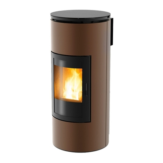
3-INSTALLATION AND ASSEMBLY DRAWINGS AND CHARACTERISTICS TUBE DIMENSIONS COMFORT AIR MODEL... - Page 17 3-INSTALLATION AND ASSEMBLY TECHNICAL CHARACTERISTICS TUBE - COMFORT AIR model Type of fuel Pellets Nominal thermal power 8 kw / 6,880 kcal Minimal thermal power 2.4 kw / 2,064 kcal Efficiency at Max 91,7% Efficiency at Min 94,1% Temperature of exhaust smoke at Max 170 ℃...
- Page 18 PREPARATION AND UNPACKING The Tube stove is delivered in a single package and the sides and the top are already fitted to the structure. Open the package, remove the four brackets (B) that block the product to the pallet by removing screws (A) and extracting the bracket (B) from under the feet "J"...
- Page 19 3-INSTALLATION AND ASSEMBLY The product must always remain in a vertical position and handled solely with a cart. Pay particular attention to the door and its glass, protecting them from mechanical knocks that would compromise their integrity. In any case, the product must always be handled with care. If possible, unpack the product near the place of installation. The packaging materials are neither toxic nor harmful, and therefore no particular disposal measures are required.
- Page 20 3-INSTALLATION AND ASSEMBLY CONNECTING THE HOT AIR DUCTING FOR COMFORT AIR MODELS Once the product is set in place, the hot air piping can be installed. The COMFORT AIR stoves are supplied as standard with a hot air diffuser, which has an air diverter E within. Therefore, the hot air that comes out from the rear flange of the stove meets this diverter inside the diffuser E and is then directed to the right and left of the room;...
- Page 21 3-INSTALLATION AND ASSEMBLY If the wall that is to be drilled through is made of flammable material, the INSTALLER MUST adequately insulate the pipe of the stove that passes through it, using suitable insulating material (1.3 - 5 cm thick with min. thermal conductivity 0.07 W/m°K). However, the pipe inserted in the wall must be adequately insulated in order not to disperse heat and soundproof the released air.
- Page 22 3-INSTALLATION AND ASSEMBLY REMOVING THE CLADDING Remove the top as follows: lift cover L. • Remove cover M; remove the three screws that fasten the slide of cover M from the structure and extract plate G from T in cover L. •...
- Page 23 3-INSTALLATION AND ASSEMBLY LATERAL SIDES "O" Proceed as follows to remove the lateral sides O: • remove the two screws Y that block panel O to the structure. Lift panel O for it come out of the pins on the lower part. •...
- Page 24 3-INSTALLATION AND ASSEMBLY FRONT PANEL "P" After having removed the lateral sides, remove: • the two screws K on the right and left of the panel. Lift the front panel P for it come out of the pins on the lower part of the stove. •...
- Page 25 3-INSTALLATION AND ASSEMBLY ELECTRICAL CONNECTION First connect the power cable on the rear side of the stove and then to a wall socket. The main switch on the rear side must only be activated when the stove is used; otherwise, it is advisable to keep it off. It is recommended to disconnect the power cable when the stove is not used.
- Page 26 3-INSTALLATION AND ASSEMBLY BEFORE START-UP GENERAL PRECAUTIONS Remove all components that could burn from the brazier and the glass (manual, various adhesive labels and any polystyrene). Check that the brazier is positioned correctly and rests properly on the base. After a long period of inactivity, remove any pellets left in the hopper (using a vacuum cleaner with a long pipe), as they could have absorbed moisture, thereby altering their original characteristics and no longer being suitable for combustion.
-
Page 27: 4-Operation
4-OPERATION It is good practice to guarantee effective ventilation in the room during the initial start-up, as the stove will emit some smoke and smell of paint. Do not stand close to the stove and air the room. The smoke and smell of paint will disappear after about an hour of operation, however, they are not harmful in any case. - Page 28 4-OPERATION LOADING THE PELLETS Fuel is loaded from the upper part of the stove by opening the door. Pour the pellets into the hopper. This is easier if performed in two steps: • Pour half the contents into the hopper and wait for the fuel to settle at the bottom. •...
-
Page 29: 5-Lcd Remote Control
5-LCD REMOTE CONTROL GENERAL SPECIFICATIONS OF THE LCD REMOTE CONTROL The remote control works at a transmission frequency of 434.5 MHz. Power the product with 3 AAA batteries as follows: • remove the cover of the battery compartment by pressing and lifting the point indicated by the arrow. •... -
Page 30: Remote Control Operation
5-LCD REMOTE CONTROL REMOTE CONTROL OPERATION GENERAL RULES Press key A for 1” to switch the product on and off. All changes are made with keys C. Key E is used to confirm the changes. Key B is used to select the product operating mode. - Page 31 5-LCD REMOTE CONTROL TIMER MODE (TIMER) Select this operating mode to switch the product on and off automatically, according to 6 customised time bands (P1 – P6). The following can be set for each time band: • start-up time. • Shutdown time.
- Page 32 5-LCD REMOTE CONTROL VARIOUS SETTINGS ROOM VENTILATION The room ventilation can be adjusted as desired in all 4 operating modes described earlier on. Simply follow the steps below: press key D on the initial display to access the VENTILATION setting. Then press key C to set the desired ventilation by selecting one of the 5 levels available.
- Page 33 5-LCD REMOTE CONTROL TIMER SETTINGS DISPLAYING THE TIMER TIME BANDS Simply press key D for 2" to display the time bands in TIMER mode. The 6 time bands can be scrolled through with key C, thereby verifying all the saved settings. Press key D or A to return to the initial display. MO TU WE TH FR SA SU 6:30 8:00...
-
Page 34: 6-Emergency Panel
6-EMERGENCY PANEL EMERGENCY PANEL There is an emergency panel on the product side, designed for any malfunction to be detected and product control if the remote control should malfunction. Three-digit display that indicates a variety of product information besides the identification code of any malfunction. GREEN LED that indicates: •... - Page 35 6-EMERGENCY PANEL EMERGENCY PANEL START-UP/SHUTDOWN If the remote control is faulty or the batteries are flat, the product can be operated in safe mode via the rear emergency panel. In this configuration, the product can only work in manual mode and one of 3 power levels can be selected. •...
- Page 36 6-EMERGENCY PANEL FEED SCREW LOADING This function can only be activated when the stove is off and allows the pellets to be loaded into the feed screw (loading system). It can be used each time the pellets finish in the feed screw and hopper (see alarm A02). It is useful to prevent failed start-ups (alarm A01) due to the hopper being empty.
-
Page 37: 7-Safety Devices And Alarms
7-SAFETY DEVICES AND ALARMS SAFETY DEVICES The product is supplied with the following safety devices: SMOKE TEMPERATURE PROBE Detects the temperature of the smoke, thereby enabling start-up or stopping the product when the temperature drops below the preset value. PELLET HOPPER SAFETY THERMOSTAT If the temperature exceeds the preset safety value, it immediately stops the product, which must cool down before being restarted. - Page 38 7-SAFETY DEVICES AND ALARMS ALARM ALERTS If an operating anomaly occurs, the product enters the shutdown phase due to an alarm and informs the user regarding the type of fault by means of a 3 digit code that remains displayed on the emergency panel. The alarm is indicated permanently by the relative 3 digit code, a flashing red LED that lights up on the emergency panel and an intermittent buzzer for the first 10 minutes.
- Page 39 7-SAFETY DEVICES AND ALARMS The spark plug is faulty. Contact an authorised service centre to have the component replaced. Pellet supply fault. Contact an authorised service centre to have the component replaced. The remote control has been out of the product Move the remote control within the product reception reception range for over 3 hours (or the batteries range (or change the batteries of the remote control if...
- Page 40 7-SAFETY DEVICES AND ALARMS BLOCKED PRODUCT The following may cause the product to be mechanically blocked: • the structure overheats (“A03”). • The smoke is overheated (“A04”). • During product operation, air that has not been controlled in the combustion chamber has entered or the chimney is clogged (“A05”). SOLUTIONS: if “A03”...
-
Page 41: 8-Maintenance And Cleaning
8-MAINTENANCE AND CLEANING EXAMPLE OF A CLEAN BRAZIER EXAMPLE OF A DIRTY BRAZIER ATTENTION! All the cleaning operations of all parts must be performed with a completely cold product and the plug disconnected. The product requires little maintenance if used with certified good quality pellets. DAILY OR WEEKLY CLEANING PERFORMED BY THE USER Before each start-up Clean the ash and any deposits in the brazier that could clog the air passage holes. - Page 42 8-MAINTENANCE AND CLEANING CLEANING THE AIR FILTER The metal mesh air filter is inserted in the rear part of the product, in line with the Ø 5 cm combustion air inlet pipe, and its aim is to prevent dirt from entering the motor body and the internal sensor. It is recommended to verify the filter is clean every 15/20 days.
- Page 43 8-MAINTENANCE AND CLEANING CLEANING THE UPPER EXCHANGER Perform the following operations with the stove switched off and cold to clean the upper exchanger. 1. Remove top A 2. Remove the lateral sides B 3. Remove the front panel C 4. Remove the upper cap D, which is beneath top A, by removing the two screws on the right side and the 2 on the left side E. Then remove the six upper screws F.
- Page 44 8-MAINTENANCE AND CLEANING CLEANING THE LOWER COMPARTMENT Once the upper exchanger is cleaned, remove plate, remove the ash pan P and brazier Q and empty them. Then remove plate R from under the ash pan P by removing the four screws S and use the nozzle of a vacuum cleaner to remove the ash and soot accumulated in the lower exchanger and around the brazier.
- Page 45 8-MAINTENANCE AND CLEANING END-OF-SEASON SHUTDOWN At the end of each season, before switching the product off, it is recommended to remove all the pellets from the hopper with a vacuum cleaner that has a long pipe. The appliance must be disconnected from the mains when it is not used. It is recommended to remove the power cable for additional safety, especially in the presence of children.
-
Page 46: 9-Problems/Causes/Solutions
9-PROBLEMS/CAUSES/SOLUTIONS ATTENTION! All repairs must only be carried out by a specialised technician, with the product switched off and the plug disconnected. If the product is NOT used as described in this manual, the manufacturer declines all liability for any damage caused to persons and property. - Page 47 9-PROBLEMS/CAUSES/SOLUTIONS ANOMALY POSSIBLE CAUSES SOLUTIONS The product works for a few minutes Start-up phase is not completed. Repeat start-up. and then switches off. Temporary power cut. Wait for the automatic restart. Clogged smoke duct. Clean the smoke duct. Faulty or malfunctioning temperature Check and replace the probes.
- Page 48 9-PROBLEMS/CAUSES/SOLUTIONS ANOMALY POSSIBLE CAUSES SOLUTIONS The product always runs at maximum The room thermostat is in the maximum Set the thermostat temperature again. power when in automatic mode. position. Faulty temperature probe. Check the probe and replace it, if necessary. Faulty or malfunctioning control panel. Check the panel and replace it, if necessary. Thermostat is set to minimum. Set the thermostat temperature again.
-
Page 49: 10-Wiring Diagrams
10-WIRING DIAGRAMS MOTHERBOARD WIRING KEY EMERGENCY PANEL GEAR MOTOR SMOKE PROBE CONTACT THERMOSTAT MODEM CONNECTION AIR FAN SWITCH SMOKE EXPULSION FAN REV CONTROL SPARK PLUG AIR DOOR SENSOR SMOKE EXPULSION FAN N.B. The wiring of the individual components is fitted with pre-wired connectors of different sizes. Technical Dept. - Page 52 MCZ GROUP S.p.A. Via La Croce n°8 33074 Vigonovo di Fontanafredda (PN) – ITALY Telefono: 0434/599599 r.a. Fax: 0434/599598 Internet: www.mcz.it e-mail: mcz@mcz.it For further technical information, regarding installation or operation please contact the TECHNICAL ASSISTANCE – AFTER-SALES DEPARTMENT Monday to Friday 8.00 to 12.00 and 14.00 to 18.00...
Need help?
Do you have a question about the tube and is the answer not in the manual?
Questions and answers