Table of Contents
Advertisement
Quick Links
This Manual is prepared for the use of trained Vulcan Service
Technicians and should not be used by those not properly
qualified.
This manual is not intended to be all encompassing. If you have
not attended a Vulcan Service School for this product, you should
read, in its entirety, the repair procedure you wish to perform to
determine if you have the necessary tools, instruments and skills
required to perform the procedure. Procedures for which you do
not have the necessary tools, instruments and skills should be
performed by a trained Vulcan Service Technician.
The reproduction, transfer, sale or other use of this Manual,
without the express written consent of Vulcan, is prohibited.
This manual has been provided to you by ITW Food Equipment
Group LLC ("ITW FEG") without charge and remains the property
of ITW FEG, and by accepting this manual you agree that you will
return it to ITW FEG promptly upon its request for such return at
any time in the future.
A product of Vulcan-Hart
SERVICE MANUAL
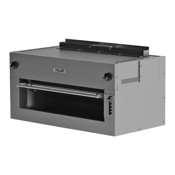
SALAMANDER ELECTRIC
BROILER
VULCAN -
36ESB
- NOTICE -
3600 North Point Blvd Baltimore, MD 21222
F45545 (0315)
Advertisement
Table of Contents

Related Manuals for Vulcan-Hart 36ESB


Summary of Contents for Vulcan-Hart 36ESB
- Page 1 ITW FEG, and by accepting this manual you agree that you will return it to ITW FEG promptly upon its request for such return at any time in the future. A product of Vulcan-Hart 3600 North Point Blvd Baltimore, MD 21222 F45545 (0315)
-
Page 2: Table Of Contents
SALAMANDER ELECTRIC BROILER TABLE OF CONTENTS GENERAL ....................3 INTRODUCTION . -
Page 3: General
Salamander Broilers. Procedures in this manual will GRID POSITION AND HEAT apply to all models unless specified. Pictures and CONTROL SETTING illustrations will be of model 36ESB unless otherwise noted. For detailed information refer to OPERATING THE All of the information, illustrations and specifications... -
Page 4: Tools
SALAMANDER ELECTRIC BROILER - GENERAL TOOLS Standard • Standard set of hand tools • VOM with ability to measure micro amp current. VOM with minimum of NFPA-70E CAT III 600V, UL/CSA/TUV listed. Sensitivity of at least 20,000 ohms per volt. Meter leads must also be rated at CAT III 600V. -
Page 5: Removal And Replacement Of Parts
SALAMANDER ELECTRIC BROILER - REMOVAL AND REPLACEMENT OF PARTS REMOVAL AND REPLACEMENT OF PARTS FRONT PANEL Disconnect the electrical power to the machine and follow lockout / tagout procedures. Remove screws that secure front panel to broiler. Remove INFINITE SWITCH / 3 HEAT SWITCH from front panel. -
Page 6: Right Side Panel
SALAMANDER ELECTRIC BROILER - REMOVAL AND REPLACEMENT OF PARTS RIGHT SIDE PANEL Disconnect the electrical power to the machine and follow lockout / tagout procedures. Remove crumb tray. Remove FRONT PANEL. Remove screws securing plate stop to broiler. Fig. 5 Remove screws securing right side panel to broiler. -
Page 7: Rack Springs
SALAMANDER ELECTRIC BROILER - REMOVAL AND REPLACEMENT OF PARTS Remove washer nut securing switch to front Loosen nuts to remove any remaining tension on panel. springs. Access the bottom of broiler and remove springs from the lower arm casting and eye bolt. Fig. - Page 8 SALAMANDER ELECTRIC BROILER - REMOVAL AND REPLACEMENT OF PARTS Fig. 13 Fig. 10 Note wire locations and disconnect wires from heating element. Grasp the rack assembly near the broiler, rotate both the rack stops horizontally and pull the rack assembly out enough for the rack assembly frame to clear the rack stops.
-
Page 9: Service Procedures And Adjustments
SALAMANDER ELECTRIC BROILER - SERVICE PROCEDURES AND ADJUSTMENTS SERVICE PROCEDURES AND ADJUSTMENTS Certain procedures in this section require electrical test or measurements while power is applied to the machine. Exercise extreme caution at all times and follow Arc Flash procedures. If test points are not easily accessible, disconnect power and follow Lockout/Tagout procedures, attach test equipment and reapply power to test. -
Page 10: Heating Elements Test
SALAMANDER ELECTRIC BROILER - SERVICE PROCEDURES AND ADJUSTMENTS If both measured values are approximately the same as listed in the machine information table, then heating elements are functioning properly. If one or both of the measured values do not agree with the values listed in the machine information table, then heating element is malfunctioning. -
Page 11: Electrical Operation
SALAMANDER ELECTRIC BROILER - ELECTRICAL OPERATION ELECTRICAL OPERATION COMPONENT FUNCTION Infinite Load Switch . . . Two switches independently control the left and right heating elements on 208V and 240V models. Depending on switch setting, provides a range of ON time from 7% to 100%. 3 Heat, 4 Position Two switches independently control the left and right heating elements on 480 volt Switch . -
Page 12: 208/240V - Wiring Diagram
SALAMANDER ELECTRIC BROILER - ELECTRICAL OPERATION 208/240V - WIRING DIAGRAM Fig. 16 F45545 (0315) Page 12 of 14... -
Page 13: 480V - Wiring Diagram
SALAMANDER ELECTRIC BROILER - ELECTRICAL OPERATION 480V - WIRING DIAGRAM Fig. 17 Page 13 of 14 F45545 (0315) -
Page 14: Troubleshooting
SALAMANDER ELECTRIC BROILER - TROUBLESHOOTING TROUBLESHOOTING TROUBLESHOOTING SYMPTOM POSSIBLE CAUSES No power to broiler. Infinite (208V/240V) or 3 heat switches (480V) are OFF or No heat. malfunctioning. Heating elements inoperative or malfunctioning. Cooking problems (product not done/ Refer to Installation & Operation Manual for recommended grid overdone).
Need help?
Do you have a question about the 36ESB and is the answer not in the manual?
Questions and answers