Table of Contents
Advertisement
Your new tool has been engineered and manufactured to WEN's highest standards for dependability,
ease of operation, and operator safety. When properly cared for, this product will supply you years
of rugged, trouble-free performance. Pay close attention to the rules for safe operation, warnings,
and cautions. If you use your tool properly and for intended purpose, you will enjoy years of safe,
reliable service.
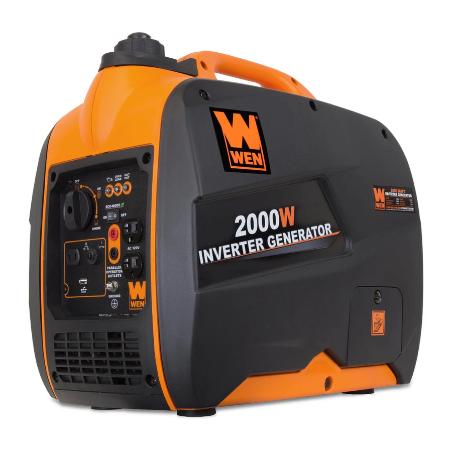
2000W INVERTER
GENERATOR
IMPORTANT:
NEED HELP? CONTACT US!
Have product questions? Need technical support?
Please feel free to contact us at:
800-232-1195
techsupport@wenproducts.com
WENPRODUCTS.COM
Model # 56200i
bit.ly/WENvideo
(M-F 8AM-5PM CST)
Advertisement
Table of Contents

Related Manuals for Wen 56200i


Summary of Contents for Wen 56200i
- Page 1 IMPORTANT: Your new tool has been engineered and manufactured to WEN’s highest standards for dependability, ease of operation, and operator safety. When properly cared for, this product will supply you years of rugged, trouble-free performance. Pay close attention to the rules for safe operation, warnings, and cautions.
-
Page 2: Table Of Contents
TABLE OF CONTENTS Generator Identification Service Record Introduction Safety Information General Safety Procedures Important Safety Instructions Generator Components Generator Preperation Starting the Generator Stopping the Generator Subsequent Starting of the Generator Using the Generator Maintenance & Care Storage & Transport Specifications Troubleshooting Exploded View and Parts List... -
Page 3: Generator Identification
GENERATOR IDENTIFICATION If assistance for information or service is required, please contact the Customer Service Help Line by calling 800-232-1195; customer will be asked to provide generator information when calling. Refer to the illustration below for the location of the serial number. Record generator information in the spaces provided below. -
Page 4: Introduction
Every effort has been made to ensure the accuracy of the information in this manual. WEN® reserves the right to change this product and specifications at any time without prior notice. Please keep this manual available to all users during the entire life of the generator. -
Page 5: General Safety Procedures
GENERAL SAFETY PROCEDURES For any questions regarding the hazard and safety notices listed in this manual or on the product, please call (800) 232-1195 M-F 8-5 CST before using the generator. DANGER: CARBON MONOXIDE Using a generator indoors CAN KILL YOU IN MINUTES. Generator exhaust contains carbon monoxide (CO). This is a poison gas you cannot see or smell. -
Page 6: Important Safety Instructions
Turn off all connected electrical devices before stopping the generator. Turn the engine switch to “OFF” position when the engine is not running. IMPORTANT SAFETY INSTRUCTIONS SAVE THESE INSTRUCTIONS – This manual contains important instructions for the WEN 2000W inverter ®... -
Page 7: Generator Components
GENERATOR COMPONENTS Use the illustrations below to become familiar with the locations and functions of the various components and controls of this generator. Fuel Cap Vacuum Relief Valve 3-in-1 Switch Recoil Starter Idle Switch 120V Duplex Receptacle Circuit Breaker Grounding Nut 12V DC Outlet USB Charger... -
Page 8: Generator Preperation
GENERATOR PREPARATION USING THE GENERATOR FOR THE FIRST TIME The following section describes steps necessary to prepare the generator for use. If after reading this sec- tion, you are unsure about how to perform any of the steps please call (800) 232-1195 M-F 8-5 CST for customer service. - Page 9 GENERATOR PREPARATION Step 2 - ADD GASOLINE WARNING: This generator may emit highly flammable and explosive gasoline vapors, which can cause severe burns or even death if ignited. A nearby open flame can lead to explosion even if not directly in contact with gasoline. Use fresh (within 30 days from purchase), lead-free gasoline with a minimum of 87 octane rating.
-
Page 10: Starting The Generator
STARTING THE GENERATOR Before starting the generator, make sure you have read and performed the steps in the “Generator Preperation” section of this manual. If you are unsure about how to perform any of the steps in this manual please call (800) 232-1195 M-F 8-5 CST for customer service. -
Page 11: Starting The Engine
STARTING THE GENERATOR STARTING THE ENGINE To start the generator, perform the following steps: 1. Unplug all electrical devices from the generator during starting. Otherwise it can be difficult for the engine to start. 2. Check that the generator is properly grounded (Refer to “Ground the Generator”). 3. -
Page 12: Stopping The Generator
STARTING THE GENERATOR IDLE CONTROL SWITCH (ESC) This generator is equipped with an Idle Control Switch. En- gaging the switch will automatically adjust the engine speed. When an electrical device comes on line, the generator en- gine will automatically speed up to supply the power needed and will slow down as the need decreases. - Page 13 SUBSEQUENT STARTING OF THE GENERATOR To check or add oil, follow these steps: 1. Place the generator on a level surface. 2. Open access panel. Clean around oil fill hole. Remove dipstick and wipe the dipstick with a clean rag. In- sert the dipstick into the oil fill opening without screwing in.
-
Page 14: Using The Generator
The surge wattage ability of the generator covers this extra power requirement. Item Rated (Running) Wattage Surge Wattage 56200i 1600 2000 Figure 6 - Generator Wattage The total running wattage requirement of the electrical devices connected to the generator should not exceed the rated wattage of the generator itself. - Page 15 USING THE GENERATOR CAUTION: The generator can run at its surge wattage capacity for only a short time. Connect electrical devices requiring a rated (running) wattage equal to or less than the rated wattage of the generator. Never connect devices requiring a rated wattage equal to the surge wattage of the generator.
- Page 16 USING THE GENERATOR CAUTION: Do not connect 50Hz loads to the generator. SOME NOTES ABOUT POWER CORDS Long or thin cords can drain the power provided to an electrical device by the generator. When using such cords, allow for a slightly higher rated wattage requirement by the electrical device. See Figure 8 for recommended cords based on the power requirement of the electrical device.
-
Page 17: Maintenance & Care
MAINTENANCE & CARE CLEANING THE GENERATOR Never clean the generator when it is running! Never clean with a bucket of water or a hose. Water can get inside the working parts of the generator and cause a short circuit or corrosion. Always try to use the generator in a cool, dry place. - Page 18 MAINTENANCE & CARE To refill the crankcase with oil, follow these steps: 1. Make sure the generator is on a level surface. Tilting the generator to assist in filling will cause oil to flow into engine areas and will cause damage. Keep generator level! 2.
- Page 19 MAINTENANCE & CARE SPARK PLUG MAINTENANCE The spark plug is important for proper engine operation. A good spark plug should be intact, free of deposits, and properly gapped. Refer to Recommended Maintenance Schedule in Figure 9. To inspect the spark plug: 1.
-
Page 20: Storage & Transport
MAINTENANCE & CARE DRAINING THE FUEL TANK Clean fuel tank each year or before storing the generator for extended periods of time. To drain the fuel tank and carburetor: 1. Set idle control switch to “ON” position. Start generator without any device connected to it. Turn the fuel valve to “off”... -
Page 21: Specifications
SPECIFICATIONS DC output Rated Voltage 12 VDC Rated Amperage 8.3 A Rated Wattage 100 W USB Charger 5V, 1 A AC output Rated Wattage 1600 Watts Surge Wattage 2000 Watts Rated Voltage 120 V Rated Amperage 13.3 A Frequency 60 Hz Phase Single Length: 20.50 inches... -
Page 22: Troubleshooting
TROUBLESHOOTING IMPORTANT: If trouble persists, please call our customer help line at (800) 232-1195 M-F 8-5 Central Time. Problem Cause Solution Engine will not start Engine switch in “OFF” position Set engine switch to “CHOKE” position. Engine is filled with Change the fuel in the tank. -
Page 23: Exploded View And Parts List
EXPLODED VIEW AND PARTS LIST FIG.1 Engine FIG.2 Fuel Tank ITEM # STOCK # DESCRIPTION Fig.2-1 56200-0201 FUEL TANK ITEM # STOCK # DESCRIPTION Fig.2-2 56200-0202 FUEL FILTER Fig.1-1 56200-0101 ENGINE Fig.2-3 56200-0203 FUEL TANK COVER Fig.1-2 56200-0102 SCREW Fig.2-4 56200-0204 OIL SEAL CLAMP Fig.2-5... - Page 24 EXPLODED VIEW AND PARTS LIST FIG.4 DECORATION SHEILD ITEM # STOCK # DESCRIPTION Fig.4-1 56200-0401 RIGHT COVER Fig.4-2 56200-0402 RIGHT SHELL Fig.4-3 56200-0403 LEFT SHELL Fig.4-4 56200-0404 LEFT COVER Fig.4-5 56200-0405 RIGHT DECORATION COVER Fig.4-6 56200-0406 WASHER AND SCREW Fig.4-7 56200-0407 BOLT Fig.4-8...
- Page 25 EXPLODED VIEW AND PARTS LIST FIG.5 INVERTOR ASSEMBLY FIG.6 CONTROL PANEL ITEM # STOCK # DESCRIPTION Fig.6-1 56200-0601 SCREW Fig.6-2 56200-0602 DC OUTLET ITEM # STOCK # Fig.6-3 56200-0603 IDEL SWITCH DESCRIPTION Fig.6-4 56200-0604 GROUNDING TERMINAL Fig.5-1 56200-0501 BOTTOM PLATE Fig.6-5 56200-0605 DUPLEX RECEPTACLE Fig.5-2...
- Page 26 EXPLODED VIEW AND PARTS LIST FIG.7 ROTOR/STATOR FIG.8 CYLINDER HEAD/ SPARK PLUG ITEM # STOCK # DESCRIPTION Fig.7-1 56200-0701 BOLT ITEM # STOCK # Fig.7-2 56200-0702 MOTOR SHROUD DESCRIPTION Fig.7-3 56200-0703 STATOR COMP CYLINDER HEAD Fig.8-1 56200-0801 Fig.7-4 56200-0704 ROTOR COMP GASKET CYLINDER HEAD Fig.7-5...
- Page 27 EXPLODED VIEW AND PARTS LIST FIG.9 CRANKCASE/CRANKCASE COVER FIG.10 PISTON RING SET / CONNECTING ROD ITEM # STOCK # DESCRIPTION ITEM # STOCK # DESCRIPTION CRANKCASE 56200-0901 Fig.10-1 56200-1001 CRANKSHAFT Fig.9-1 ASSEMBLY 56200-0902 OIL-SEAL Fig.9-2 Fig.10-3 56200-1003 CONNECTING ROD 56200-0903 BEARING Fig.9-3 Fig.10-4 56200-1004 PISTON 56200-0904 CRANKCASE...
- Page 28 EXPLODED VIEW AND PARTS LIST FIG.13 CARBURETOR ASSEMBLY FIG.14 AIR CLEANER ITEM # STOCK # DESCRIPTION ITEM # STOCK # DESCRIPTION Fig.14-1 56200-1401 AIR CLEANER CARBURETOR 56200-1402 AIR CLEANER Fig.13-1 Fig.14-2 56200-1301 GASKET GASKET CARBURETOR AIR CLEANER Fig.13-2 Fig.14-3 56200-1403 56200-1302 INSULATOR PLATE INTAKE DUCT...
-
Page 29: Wiring Diagram
WIRING DIAGRAM... -
Page 30: Warranty Statement
WEN® will repair or replace, at its discretion, any part that is proven to be defective in materials or workman- ship under normal use during the two (2) years warranty period. Warranty repairs or replacements will be made without charge for parts or labor.
Need help?
Do you have a question about the 56200i and is the answer not in the manual?
Questions and answers