Table of Contents
Advertisement
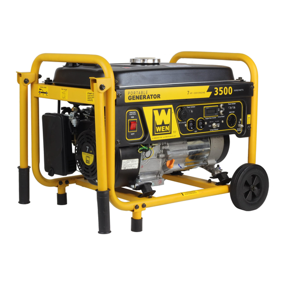
MODEL 3500
HP Generator
Item # 56352
Owner's Manual
Manual del Propietario
Questions? Problems?
Please call our customer help line:
(800) 232-1195
M-F 8-5 CST
FEATURES
3500 Surge Watt Output
3000 Rated Watt Output
Powerful Enough to Run Essential Appliances During Power Outages
120 and 240 Volt AC Outputs
Low Oil Automatic Shutoff
Circuit Breaker for Overload Protection
4 Gallon Fuel Tank Capacity
Engine Hour Counter
Cigarette Lighter Style 12V DC Outlet
Spark Arrester
Meets EPA Emission Standards
Advertisement
Table of Contents

Related Manuals for Wen 3500


Summary of Contents for Wen 3500
- Page 1 Please call our customer help line: (800) 232-1195 M-F 8-5 CST FEATURES 3500 Surge Watt Output 3000 Rated Watt Output Powerful Enough to Run Essential Appliances During Power Outages 120 and 240 Volt AC Outputs Low Oil Automatic Shutoff ...
-
Page 3: Generator Identification
GENERATOR IDENTIFICATION For information and questions, please contact the Customer Service Help Line by calling 800-232- 1195. Certain information will be requested by the Customer Service Representative and to facilitate that, please fill in the information below. Refer to the illustration below for the location of Serial Number. Record generator information in the spaces provided below. -
Page 4: Table Of Contents
TABLE OF CONTENTS GENERATOR IDENTIFICATION ....................i SERVICE RECORD ......................... i INTRODUCTION ..........................1 SAFETY INFORMATION ......................2 GENERAL SAFETY PROCEDURES ................... 3 IMPORTANT SAFETY INSTRUCTIONS ................... 5 PACKAGE CONTENTS ......................... 8 GENERATOR COMPONENTS ..................... 9 ASSEMBLY ............................ 10 Attach Feet ..........................10 Attach Handles ......................... -
Page 5: Introduction
INTRODUCTION Thank You for Purchasing a WEN Power Product. This manual provides information regarding the safe operation and maintenance of this product. Every effort has been made to ensure the accuracy of the information in this manual. WEN Power reserves the right to change this product and specifications at any time without prior notice. -
Page 6: Safety Information
SAFETY INFORMATION Before operating this generator read and observe all warnings, cautions, and instructions on this sheet, on the generator, and in the Owner’s Manual. NOTE: The following safety information is not meant to cover all possible conditions and situations that may occur. Read the entire Owner’s Manual for safety and operating instructions. -
Page 7: General Safety Procedures
GENERAL SAFETY PROCEDURES For any questions regarding the hazard and safety notices listed in this manual or on the (800) 232-1195 M-F 8-5 CST product, please call before using the generator. DANGER : CARBON MONOXIDE. Using a generator indoors CAN KILL YOU IN MINUTES. - Page 8 WARNING : This generator produces powerful voltage, which can result in electrocution. ALWAYS ground the generator before using it (see the “Ground the Generator” portion of the “GENERATOR PREPARATION” section). Generator should only be plugged into electrical devices, either directly or with an extension cord.
-
Page 9: Important Safety Instructions
IMPORTANT SAFETY INSTRUCTIONS SAVE THESE INSTRUCTIONS – This manual contains important instructions for WEN 3500 generator that should be followed during installation and maintenance of the generator. Generators vibrate in normal use. During and after the use of the generator, inspect the generator as well as extension and power supply cords connected to it for damage resulting from vibration. -
Page 12: Package Contents
PACKAGE CONTENTS Your generator comes with the items listed below. Please check to see that all of the following items are included with your generator. (800) 232-1195 If there are any damaged or missing items, please call M-F 8-5 CST for customer service. -
Page 13: Generator Components
GENERATOR COMPONENTS Please familiarize yourself with the locations and functions of the various components and controls of your generator. (1) Fuel Cap- Access to the fuel tank for adding (9) 12V Cigarette lighter Style DC Receptacle. (10) Oil Fill and Dipstick- Location for checking and fuel. -
Page 14: Assembly
ASSEMBLY In order to best protect the generator while in the package, this product comes with some components disassembled. Please complete the following assembly steps before proceeding to use the generator. For ease of assembly, we recommend attaching the components in the order listed in this manual. -
Page 15: Attach Handles
Attach Handles The handles attach to the same end of the generator as the feet. To attach the handles to the generator, perform the following steps: 1. Place one handle onto the upper portion of the generator frame as shown in figure 3. 2. - Page 16 Figure 4- supporting the generator Figure 5- axle assembly Figure 6- wheel installation...
-
Page 17: Generator Preparation
GENERATOR PREPARATION Using the Generator for the First Time The following section describes steps necessary to prepare the generator for use. If after (800) reading this section, you are unsure about how to perform any of the steps please call 232-1195 M-F 8-5 CST for customer service. -
Page 18: Step 2- Add Gasoline
Gasoline can age in the tank and make it hard to start up the generator in the future. Never store generator for extended periods of time with fuel in the tank. Model number 3500 Fuel tank 15 L (4 gallons) -
Page 19: Step 3- Ground The Generator
Step 3- Ground the Generator WARNING: Failure to properly ground the generator can result in electrocution. Ground the generator by tightening the grounding nut against a grounding wire (see figure 11). A generally acceptable grounding wire is a No. 12 AWG (American Wire Gauge) stranded copper wire. -
Page 20: Starting The Generator
STARTING THE GENERATOR Before starting the generator, make sure you have read and performed the steps in the “Generator Preparation” section of this manual. If you are unsure about how to perform any (800) 232-1195 M-F 8-5 CST of the steps in this manual please call for customer service. -
Page 21: Subsequent Starting Of The Generator
To start your generator, perform the following steps: 1. No electrical devices should be connected to the generator during starting. Devices can make it difficult for the engine to start. 2. Check that the generator is properly grounded (see “Ground the Generator”). 3. -
Page 22: Step 2 - Check The Fuel Level
To check or add oil, follow these steps: 1. Make sure the generator is on a level surface. Clean around oil fill. 2. Remove the oil filler/dipstick cap and check oil level. 3. If oil level is below the second thread from the lip of the oil fill opening, slowly add oil until the engine crankcase is filled. -
Page 23: Using The Generator
Model Number Rated(Running) Wattage Surge Wattage 3500 3000 3500 Figure 15- generator wattage by model number. The total running wattage requirement of the electrical devices connected to the generator should not exceed the rated wattage of the generator itself. - Page 24 When the rated wattage requirement of each electrical device has been determined, add these numbers to find the total rated wattage needed. If this number exceeds the rated wattage of the generator, DO NOT connect all these devices. Select a combination of electrical devices, which has a total rated wattage lower than or equal to the rated wattage of the generator.
- Page 25 2. Push in the circuit reset buttons to the “on” position (NOTE: They may be pushed in already). 3. Move the voltage selector to the desired position. Move the switch to the left to use the standard 120 Volt receptacles. Move the switch to the right to use the 240/120 Volt NEMA receptacle.
-
Page 26: Dc Usage
Device Requirements Max. Cord Length (ft) by Wire Gauge Amps Watts (120V) Watts (240 V) #8 wire #10 wire #12 wire #14 wire #16 wire 1000 1200 1800 1200 2400 1800 3600 2400 4800 3000 6000 3600 7200 4800 9600 *NR= not recommended Figure 18- Maximum Extension Cord Lengths by Power Requirement DC Usage... -
Page 27: Maintenance / Care
MAINTENANCE / CARE Proper routine maintenance of your generator will help prolong the life of your machine. Please perform maintenance checks and operations according the schedule in figure 19. If you have questions about any of the maintenance procedures listed in this manual, please call (800) 232-1195 M-F 8-5 CST. -
Page 28: Changing/ Adding Oil
Figure 20- Checking the oil Changing/ Adding Oil Change the oil according to the maintenance schedule in figure 19. Change the oil when the engine is warm. This will allow for complete drainage. Change oil more often if operating under heavy load or high ambient temperatures. -
Page 29: Air Cleaner Maintenance
Air Cleaner Maintenance Routine maintenance of the air cleaner helps maintain proper air flow to the carburetor. Check that the air cleaner is free of excessive dirt. 1. Unhinge the clasps at the top and bottom of the air cleaner cover (see figure 23). 2. -
Page 30: Spark Plug Maintenance
Spark Plug Maintenance The spark plug is important for proper engine operation. A good spark plug should be intact, free of deposits, and properly gapped. To inspect the spark plug: 1. Pull on the spark plug cap to remove it. 2. -
Page 31: Storage / Transport Procedures
STORAGE / TRANSPORT PROCEDURES Never place any type of storage cover on the generator CAUTION: while it is still hot. If the generator is being stored for short periods of time (30 – 60 days), add stabilized fuel to the fuel tank until full. -
Page 32: Specifications
SPECIFICATIONS Generator AC Output Rated Wattage 3000 W Surge Wattage 3500 W Rated Voltage 240V/120 V Rated Amperage 12.5A/25A Rated Frequency 60 Hz Phase Single Dimensions(in): length= 24.4 width= 17.7 height= 18.5 Weight 111.2 lbs Engine 4-stroke OHV single cylinder with forced air... -
Page 33: Troubleshooting
TROUBLESHOOTING IMPORTANT: If trouble persists please call our customer help line at (800) 232-1195 M-F 8-5 Central Time. Problem Cause Solution Engine will not Engine switch is set start to "OFF". Set engine switch to "ON". Fuel valve is turned to "OFF". -
Page 34: Exploded View And Parts List
EXPLODED VIEW AND PARTS LIST Engine exploded view... - Page 35 Engine parts list Item Order # Description Item Order # Description Oil drain plug Woodruff key P54000 P54122 Washer Crankshaft assembly P54002 P54123 Bearing 6205 Lock nut P54004 P54128 Crankshaft oil seal Sleeve P54008 P54130 Crankcase Valve rocker P54011 P54132 Regulating sway bar Adjusting bolt for valve gap P54014...
- Page 36 Generator exploded view...
- Page 37 Generator parts list Item Order # Description Item Order # Description Stator &rotor assembly P54868 Gasoline engine P54360 P54237 Frame comp P54369 Fuel tank (Black) P54242 Bottom rubber A P54368 Fuel cap P54244 Bottom rubber B P54372 Fuel filter P54246 Flange nut M8 P54374 Fuel gauge assembly...
-
Page 38: Wiring Diagram
WIRING DIAGRAM... - Page 39 NOTES:...
-
Page 40: Warranty Statement
Power Pro Technology along with a copy of the receipt. The information is required to process warranty claims. WEN Power™ will repair or replace, at its discretion, any part that is proven to be defective in materials or workmanship under normal use during the two (2) year warranty period.
Need help?
Do you have a question about the 3500 and is the answer not in the manual?
Questions and answers
I have a WEN generator it’s a 3500. I need to know what type of oil to put into it. I live in Phoenix Arizona.