Table of Contents
Advertisement
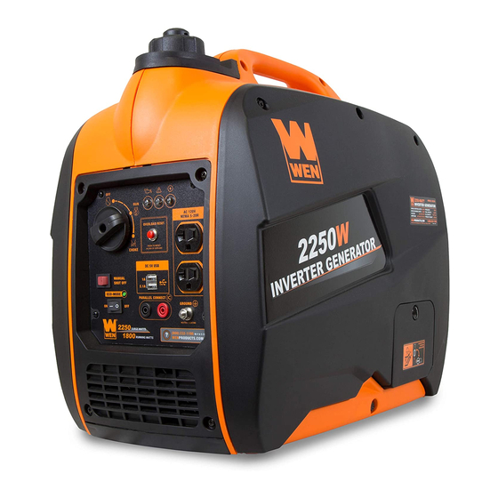
MODEL 56225i
2250W INVERTER
GENERATOR
Instruction Manual
NEED HELP? CONTACT US!
Have product questions? Need technical support? Please feel free to contact us:
1-800-232-1195 (M-F 8AM-5PM CST)
TECHSUPPORT@WENPRODUCTS.COM
IMPORTANT: Your new tool has been engineered and manufactured to WEN's highest standards for dependability,
ease of operation, and operator safety. When properly cared for, this product will supply you years of rugged,
trouble-free performance. Pay close attention to the rules for safe operation, warnings, and cautions. If you use
your tool properly and for its intended purpose, you will enjoy years of safe, reliable service.
WENPRODUCTS.COM
For replacement parts and the most up-to-date instruction manuals, visit
Advertisement
Table of Contents

Related Manuals for Wen 56225i


Summary of Contents for Wen 56225i
- Page 1 1-800-232-1195 (M-F 8AM-5PM CST) TECHSUPPORT@WENPRODUCTS.COM IMPORTANT: Your new tool has been engineered and manufactured to WEN’s highest standards for dependability, ease of operation, and operator safety. When properly cared for, this product will supply you years of rugged, trouble-free performance. Pay close attention to the rules for safe operation, warnings, and cautions. If you use your tool properly and for its intended purpose, you will enjoy years of safe, reliable service.
-
Page 2: Table Of Contents
CONTENTS WELCOME Specifications ....................3 Introduction ..................... 4 SAFETY Safety Information ................... 5 Generator Safety Warnings ................6 BEFORE OPERATING Know Your Inverter Generator ................9 Generator Preparation ..................11 OPERATION & MAINTENANCE Starting Your Generator ................. 15 Using Your Generator ..................17 Shutting Off Your Generator ................ -
Page 3: Welcome
SPECIFICATIONS GENERATOR Rated Wattage 1800 Watts Surge Wattage 2250 Watts AC: 120V Rated Voltage DC: 5V AC: 15A Rated Amperage DC: 1A (Top), 2.1A (Bottom) Phase Single Frequency 60Hz Length: 19 in. Product Dimensions Width: 11.5 in. Height: 18.2 in. Product Net Weight 48.5 lbs ENGINE... -
Page 4: Introduction
INTRODUCTION Thanks for purchasing the WEN 2250-Watt Inverter Generator. Refer to the illustration below for the location of the serial number on the side of the engine. Record the generator information in the spaces provided below. If assis- tance for information or service is required, please contact customer service by calling 1-800-232-1195, M-F 8-5 CST;... -
Page 5: Safety
WEN reserves the right to change this product and specifications at any time without prior notice. At WEN, we are continuously improving our products. If you find that your tool does not exactly match this manual, please visit wenproducts.com for the most up-to-date manual or contact customer service at 1-800-232-1195, M-F 8-5 CST. -
Page 6: Generator Safety Warnings
GENERATOR SAFETY WARNINGS DANGER! CARBON MONOXIDE Using a generator indoors CAN KILL YOU IN MINUTES. Generator exhaust contains carbon monoxide (CO). This is a poison gas you cannot see or smell. If you can smell the generator exhaust, you are breathing CO. But even if you cannot smell the exhaust, you could be breathing CO. - Page 7 GENERATOR SAFETY WARNINGS WARNING! Do not let comfort or familiarity with the product replace strict adherence to product safety rules. Failure to follow the safety instructions may result in serious personal injury. OPERATING ENVIRONMENT 3. If any part of the generator, electrical device or pow- er cord is broken, damaged, or defective, make sure 1.
- Page 8 GENERATOR SAFETY WARNINGS WARNING! Do not let comfort or familiarity with the product replace strict adherence to product safety rules. Failure to follow the safety instructions may result in serious personal injury. TO MAXIMIZE THE LIFESPAN OF YOUR GENERATOR: We recommend running your generator at least once a month for 20 to 30 minutes.
-
Page 9: Before Operating
KNOW YOUR INVERTER GENERATOR TOOL PURPOSE Inverter Generators provide you with clean and quiet power, when and where you need it most. Refer to the fol- lowing diagrams to become familiarized with all the parts and controls of your Generator. The components will be referred to later in the manual for assembly and operation instructions. - Page 10 KNOW YOUR INVERTER GENERATOR CONTROL PANEL AC 120V RESET CHOKE DC 5V MANUAL SHUT OFF ECO-MODE PARALLEL CONNECT GROUNDING 1. 3-In-1 Dial Switch 6. DC 5V USB Port Choke, Run, Off 1A & 2.1A for charging various electronic devices. 2. Indication Lights 7.
-
Page 11: Generator Preparation
GENERATOR PREPARATION The following section describes the necessary steps to prepare the generator for use. If you are unsure about how to perform any of the steps please call 1-(800) 232-1195 M-F 8-5 CST for customer service. Failure to perform these steps properly can damage the generator or shorten its life. STEP 1 - ADD / CHECK OIL The generator is shipped without oil. - Page 12 TIP: Your WEN generator is compatible with the WEN 55201 Magnetic Oil Dipstick (not included), available for purchase at wenproducts.com. The dipstick’s industrial-strength magnetic tip will collect metal shavings from your generator’s oil tank to help preserve the engine and extend your...
- Page 13 GENERATOR PREPARATION STEP 2 - ADD / CHECK FUEL WARNING! RISK OF EXPLOSION. HIGHLY FLAMMABLE: This generator may emit highly flammable and explosive gasoline vapors, which can cause severe burns or even death, if ignited. A nearby open flame can lead to explosion even if not directly in contact with gasoline.
- Page 14 GENERATOR PREPARATION STEP 3 - GROUND THE GENERATOR Fig. 7 To reduce the risk of electric shock and to maximize safety, the generator should be properly grounded. Ground the generator by tightening the grounding nut on the front control panel (Fig. 7) against a grounding wire. A gen- erally acceptable grounding wire is a No.
-
Page 15: Operation & Maintenance
STARTING YOUR GENERATOR Before starting the generator, make sure you have read and performed the steps in the “Generator Preparation” section of this manual, page 11. If you are unsure about how to perform any of the steps in this manual please call 1-(800) 232-1195 M-F 8-5 CST for customer service. - Page 16 STARTING YOUR GENERATOR Before starting the generator, check the following: Fig. 8 1. Place the generator outside on a dry, level surface. Allow at least two feet of clearance on all sides of the generator. 2. Make sure all electrical devices are unplugged from the gen- erator during ignition.
-
Page 17: Using Your Generator
USING YOUR GENERATOR CALCULATING THE WATTAGE OF YOUR DEVICE(S) Connect electrical devices running on AC current according to their wattage requirements. Calculate the total run- ning wattage and starting wattage of the device(s) you wish to connect, and MAKE SURE that they are within the capacity of your generator and the capacity of each individual outlet. - Page 18 USING YOUR GENERATOR CALCULATING THE WATTAGE OF YOUR DEVICE(S) - CONTINUED The chart below serves as a reference for the estimated wattage requirements of common electrical devices. How- ever, do not solely rely on this chart - all electronics and appliances are built differently. Always check the wattage listed on the electrical device before consulting this chart.
- Page 19 USING YOUR GENERATOR CONNECTING ELECTRICAL DEVICES When the rated wattage requirement of each electrical device has been determined, add these numbers to find the total rated wattage needed. If this number exceeds the rated wattage (1800W) of the generator, DO NOT connect all these devices.
- Page 20 1350W. PARALLEL OPERATION The parallel connection ports allow you to connect two WEN generators to increase the total available electrical power. The WEN Parallel Connection Kit can be purchased from wenproducts.com. Follow the instructions included with your parallel connection kit for proper installation and operation.
- Page 21 USING YOUR GENERATOR SOME NOTES ABOUT POWER CORDS Long or thin cords can drain the power provided to an electrical device by the generator. When using such cords, allow for a slightly higher rated wattage requirement by the electrical device. Device Requirements Max.
-
Page 22: Shutting Off Your Generator
OPTION 1: FUEL SHUT OFF (RECOMMENDED) The WEN 2250W Inverter Generator is equipped with automatic fuel shutoff. This feature turns off the flow of fuel, allowing for the generator to use up the remaining fuel from the carburetor before turning off. -
Page 23: Maintenance
MAINTENANCE Proper routine maintenance of the generator will help prolong the life of the machine. Please perform maintenance checks and operations according to the schedule in Table 4. CAUTION! Never perform maintenance operations while the generator is running. Before maintaining or servicing the generator, turn OFF the generator, disconnect all devices and allow the generator to cool down. -
Page 24: Cleaning The Generator
TIP: Your WEN generator is compatible with the WEN 55201 Magnetic Oil Dipstick (not included), available for purchase at wenproducts.com. The dipstick’s industrial-strength magnetic tip will collect metal shavings from your generator’s oil tank to help preserve the engine and extend your... - Page 25 MAINTENANCE DRAINING THE CARBURETOR We recommended draining the carburetor after every use (not necessary if the generator is shut off using the “FUEL OFF” option), and before storing the generator. Draining the carburetor can prevent the fuel from clogging up the carburetor and preventing the generator from starting. 1.
- Page 26 MAINTENANCE AIR FILTER MAINTENANCE Check every 50 hours of operation (refer to Table 4 - Recommended Maintenance Schedule). Routine maintenance of the air filter helps maintain proper airflow to the carburetor. Occasionally check that the air cleaner is free of excessive dirt. To inspect and clean the air filter: Fig.
- Page 27 MAINTENANCE DRAINING/CHANGING OIL Change the oil according to the Recommended Maintenance Schedule in Table 4. Change the oil MORE OFTEN if operating under heavy load or high ambient temperatures. It is also necessary to drain the oil from the crankcase if it has become contaminated with water or dirt. Changing the oil when the engine is warm allows for complete drainage.
-
Page 28: Spark Plug Maintenance
MAINTENANCE SPARK PLUG MAINTENANCE Refer to Recommended Maintenance Schedule in Table 4 for maintaining the spark plug. The spark plug is important for proper engine operation. Check the spark plug regularly to maintain proper engine operation. A good spark plug should be intact, free of deposits, and properly gapped. To inspect or replace the spark plug: Fig. -
Page 29: Spark Arrestor Maintenance
Replace the spark arrestor if it is damaged (replacement spark arres- tors can be purchased from wenproducts.com by search- ing the part no. 56225i-1509). 4. Reinstall the spark arrestor in the muffler and secure it in place with the screw. -
Page 30: Transportation & Storage
TRANSPORTATION & STORAGE TRANSPORTING THE GENERATOR To prevent fuel spillage when transporting, be sure to perform the following: 1. Tighten the fuel cap and turn the vacuum relief valve to “OFF”. 2. Set the engine switch to “OFF”. 3. Drain the fuel tank if possible (see “DRAINING THE FUEL TANK”). 4. -
Page 31: Troubleshooting Guide
TROUBLESHOOTING GUIDE WARNING: Stop using the generator immediately if any of the following problems occur or risk serious personal injury. If you have any questions, please contact our customer service at (800) 232-1195, M-F 8-5 CST or email us at techsupport@wenproducts.com. PROBLEM POSSIBLE CAUSE SOLUTION... -
Page 32: Wire Diagram
WIRING DIAGRAM... -
Page 33: Exploded View & Parts List
EXPLODED VIEW & PARTS LIST FIG. 1 - ENGINE PART NO. DESCRIPTION QTY. Fig. 1-1 56225i-0101 Engine Assembly FIG. 2 - FUEL TANK ASSEMBLY FIG. 3 - MUFFLER COVER PART NO. DESCRIPTION QTY. PART NO. DESCRIPTION QTY. 56200- Cover, Muffler Fig. - Page 34 EXPLODED VIEW & PARTS LIST FIG. 4 - SIDE CASING PART NO. DESCRIPTION QTY. PART NO. DESCRIPTION QTY. Side Panel Fig. 4-14 56200-0414 Jacket, Rubber 56200- Fig. 4-1 (Right)/Service 56200- Guide Starting 0401B Fig. 4-16 Panel 0416B Rope Fig. 4-2 56200-0402 Shell, Right Fig.
- Page 35 Bracket, Cush- Fig. 5-9 56200-0509 ion Rubber Bracket, Cush- Fig. 5-10 56200-0510 ion Rubber Support, In- Fig. 5-11 56200-0511 verter 56225i- Fig. 5-12 Inverter 0512 Sleeve, Fuel Fig. 5-15 56200-0515 Tank Rubber Sleeve, Fuel Fig. 5-16 56200-0516 Tank Rubber Fig. 5-17 56200-0517 Bolt Fig.
- Page 36 DESCRIPTION QTY. Fig. 6-1 56200-0601B Screw Fig. 6-20 56200-0620 Handle Choke Eco-Mode Idle Fig. 6-21 56200-0621B Cover Plate Fig. 6-3 56225i-0603 Switch Fig. 6-23 56200-0623 Ball, Steel Grounding Fig. 6-4 56200-0604 Spring, Stopper Terminal Fig. 6-24 56200-0624B Adjusting 120 Volt Duplex Fig.
- Page 37 FIG. 7 - ROTOR / STATOR ASSEMBLY PART NO. DESCRIPTION QTY. Fig. 7-1 56200-0701 Bolt Fig. 7-2 56200-0702 Shroud, Motor Fig. 7-3 56225i-0703 Stator Assembly Fig. 7-4 56200-0704 Rotor Assembly Fig. 7-5 56200-0705 Impeller Fig. 7-6 56200-0706 Bolt Fig. 7-7 56200-0707 Fig.
- Page 38 EXPLODED VIEW & PARTS LIST FIG. 8 - CYLINDER HEAD ASSEMBLY FIG. 9 - CRANKCASE ASSEMBLY PART NO. DESCRIPTION QTY. PART NO. DESCRIPTION QTY. Gasket, Cylinder Crankcase Fig. 8-1 56200-0801 Fig. 9-1 56200-0901 Head Subassembly Head Subassembly, Fig. 9-2 56200-0902 Oil-Seal Fig.
- Page 39 FIG. 11 - VALVE TRAIN / CAMSHAFT ASSEMBLY PART NO. DESCRIPTION QTY. PART NO. DESCRIPTION QTY. Camshaft Fig.10-1 56200-1001 Crankshaft Assy. Fig.11-1 56225i-1101 Assembly Fig.10-2 56225i-1002 Rod, Connecting Fig.11-2 56200-1103 Tappet, Valve Fig.10-3 56200-1003 Piston 56200-1104.1 Inner Valve Fig.11-3 Fig.10-4 56200-1004 Clip, Piston Pin 56200-1104.2...
- Page 40 FIG. 13 - CARBURETOR ASSEMBLY FIG. 12- RECOIL START ASSEMBLY PART NO. DESCRIPTION QTY. PART NO. DESCRIPTION QTY. Recoil Starter Fig.13-1 56200-1301 Gasket, Carburetor Fig.12-1 56225i-1201 Assembly Plate, Carburetor Fig.13-2 56200-1302 Fig.12-2 56200-1202B Bolt Insulator Fig.12-3 56200-1203 Bolt Gasket, Carburetor Fig.13-3...
- Page 41 56200-1502 Shroud Muffler Fig.16-2 56200-1602 Subassembly Screw Cross Fig.15-3 56200-1503 Fig.16-3 56200-1603 Bolt Groove Pan Fig.15-4 56200-1504 Muffler Assy. Fig.16-4 56225i-1604 Igniter Fig.15-5 56200-1505 Fig.16-5 56200-1605 Sensor, Engine Oil Gasket, Exhaust Fig.16-6 56200-1606 Bolt Fig.15-6 56200-1506 Outlet Fig.16-7 56200-1607 Clamp Fig.15-7...
-
Page 42: Warranty Statement
(2) years from date of purchase or 500 hours of use; whichever comes first. Ninety days for all WEN products if the tool is used for pro- fessional or commercial use. - Page 43 NOTES...
- Page 44 THANKS FOR REMEMBERING V. 2019.07.11...
Need help?
Do you have a question about the 56225i and is the answer not in the manual?
Questions and answers