Table of Contents
Advertisement
Quick Links
Advertisement
Table of Contents

Subscribe to Our Youtube Channel
Summary of Contents for Miller 1036
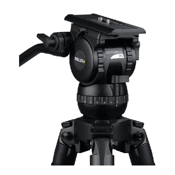
- Page 1 Fluid Head OPERATOR’S MANUAL #1036 Compass 20 Fluid Head...
-
Page 2: Features And Controls
Features and Controls Sliding Platform Sliding Platform Lock Camera Screws Pan Handle Clamp Tilt Lock Pan Lock Pan Handle Threaded Stud Clamp Nut Fig. 1... - Page 3 Features and Controls Camera Plate 1/4” + Pin Carriage Release Knob Quick Release Knob Safety Tab Tilt Drag Control Accessory Mounting Counterbalance Selector Bubble Level Pan Drag Control Fig. 2...
-
Page 4: Safety Instructions
Introduction Thank you for purchasing the Compass 20 Fluid Head. The Compass 20 Fluid Head has been designed to suit payload capacities from HDV to standard configuration XDCAM and P2HD cameras. The robust design and construction of the Compass 20 Fluid Head offers maximum stability, accuracy and durability and includes precision ball bearing mounted Fluid Drag Plate system in the Pan and Tilt assembly to deliver true fluid drag performance over the... -
Page 5: Technical Data
Technical Data Weight 2.7 kg (6.0 lb) Payload Range 2.0 – 12.0 kg (4.4 - 26.5 lb) Max. Capacity 20.0 kg (44.0 lb) Tilt Drag 5 Selectable fluid drag positions + 0 Tilt Range + 90˚ / -75˚ Tilt Lock Positive Lock caliper brake system Pan Drag 5 Selectable fluid drag positions + 0... -
Page 6: Operating Instructions
Operating Instructions The operating instructions are described in six steps. Please read and understand these instructions before using this equipment. Do not omit any steps. 1 Fluid Head Set-up 1.1 Loosen the PAN HANDLE CLAMP fully then rotate the PAN HANDLE until it is approximately perpendicular to the THREADED STUD (fig. - Page 7 The 1/4”and 3/8” screws can be stored underneath the SLIDING PLATFORM (fig. 1). 2.3 Attach camera accessories and the battery to the camera, it is recommended to estimate the camera’s Centre of Gravity (C of G) for the purpose of correctly positioning the camera on the CAMERA PLATE.
- Page 8 Operating Instructions 3. Counterbalance Control The counterbalance system was designed to neutralise the effect of the camera weight when it is tilted. The Compass 20 Fluid Head offers a 4 position counterbalance system which can be operated via the COUNTERBALANCE SELECTOR (fig. 2).
- Page 9 Operating Instructions 4. Pan / Tilt Drag Control. The Compass 20 Fluid Head offers 5 selectable positions of fluid drag + zero setting in the Pan and Tilt. The settings are equally stepped from light drag in position 1 up to heavy drag in position 5, the drag plates are completely disengaged in position zero.
-
Page 10: Maintenance
Maintenance The Compass 20 Fluid Head offers high quality surface coatings. Miller recommends keeping the Fluid Head clean at all times by using soft brushes and lint free cloth to wipe over the surfaces. • Do not immerse the Fluid Head in any liquid. •... -
Page 11: Spare Parts And Accessories
MILLER CAMERA SUPPORT EQUIPMENT 30 Hotham Parade, Artarmon, Sydney, NSW 2064 Australia Tel: +61 2 9439 6377 Email: sales@miller.com.au ITEM NO. MILLER CAMERA SUPPORT (LLC) USA P7715 218 Little Falls Road, Cedar Grove, New Jersey 07009-1231 USA #1208 Tel: (973) 857 8300 P0037 Email: sales@millertripods.us... - Page 12 MILLER CAMERA SUPPORT EQUIPMENT 30 Hotham Parade Artarmon, Sydney NSW 2064 Australia Tel: +61 2 9439 6377 Fax: +61 2 9438 2819 Email: sales@miller.com.au D 7881-1 07/09...


Need help?
Do you have a question about the 1036 and is the answer not in the manual?
Questions and answers