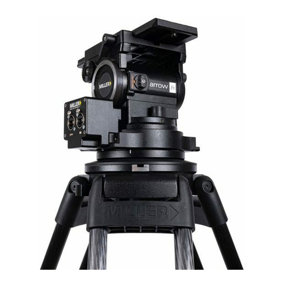
Summary of Contents for Miller Arrow Fx 16 CB Plus Series
- Page 1 Fluid Head OPERATOR’S MANUAL 1078 Arrow 3 Fluid Head 1080 Arrow 5 Fluid Head 1082 Arrow 7 Fluid Head...
- Page 2 Features and Controls Sliding Platform Lock Camera Plate Camera Screws Sliding Platform Quick Release Knob Counterbalance Selector Tilt Lock Pan Lock Pan Drag Control Illumination Button Encoder Housing Bubble Level Tilt Drag Control D100 Claw Ball CB Plus Selector Knob Clamp Nut Fig.
-
Page 3: Table Of Contents
Contents ntroduction Safety Instructions................Operating Instructions................1. Attaching Mounting Base.............. 2. Attaching Encoder Housing............3. Integration..................4. Camera Set-up................5. Counterbalance Control..............6. Pan-Tilt Drag Control..............7. Pan-Tilt Lock Control..............8. Illumination.................. Maintenance..................Battery Replacement................Storage....................Spare Parts and Accessories............... Warranty.................... -
Page 4: Safety Instructions
Ensure that all This Miller product provides the user precise pan and tilt coordinates through seperated (pan and tilt) outputs. These equipment is operating correctly and free from defects and... -
Page 5: Operating Instructions
Operating Instructions 1. Attaching Mounting Base D100 Claw Ball Mitchell Base Adapter Fig. 3 Fig. 4 The Arrow fluid head comes standard with the D100 Claw Available as an optional accessory is the Mitchell Base Adapter Ball which is attached by 3 x M5 screws, these are fixed to head (1225) which can be attached using the 4 x 3/8”... -
Page 6: Attaching Encoder Housing
Operating Instructions 2. Attaching Encoder Housing The Arrow has a removeable encoder housing which allows The output signal from the Arrow fluid head is a pulse signal (A,-A, B, -B) with a reference signal (Z,-Z) (one count for easy serviceability. The encoder housing contains the Read heads which intrepret the coordonates from the magnetic rings per revolution). -
Page 7: Integration
Operating Instructions 3. Integration The ArrowFX fluid head can be integrated in two ways. 1) The ArrowFX, coupled with a camera, can transit positional data of camera feed to allow for augmented/virtual feed overlays (fig. 7). 2) The ArrowFX can be used to control a remote head (with camera) (fig. 8). For details on an integrated Egripment control system refer to Appendix (pg 14). -
Page 8: Camera Set-Up
Operating Instructions 4. Camera Set-up 2.1 Remove the CAMERA PLATE by pulling down the SAFETY TAB while rotating the QUICK RELEASE KNOB to the left. The CAMERA PLATE should pop out. 2.2 Refer to the Camera’s owners manual for correct C of G method of attachment to the CAMERA PLATE. -
Page 9: Counterbalance Control
Operating Instructions 5. Counterbalance Control The counterbalance system was designed to neutralise the effect of the camera weight when it is tilted. The Arrow fluid head offers a 16 position counterbalance system which is operated with the CB SELECTOR KNOB and the CB PLUS SELECTOR KNOB. -
Page 10: Pan-Tilt Drag Control
Operating Instructions 6. Pan-Tilt Drag Control. Tilt Drag Setting Illumination Button Counter Balance Selector The Arrow fluid head offers 7 selectable positions of fluid drag + zero setting in the pan and tilt (5 for AFX 3). The settings are equally stepped from light drag in position 1 up to heavy drag in position 7, the drag plates are completely disengaged in position zero. -
Page 11: Maintenance
Maintenance The Arrow fluid head offers high quality surface coatings, dust and moisture seals. Miller recommends keeping the fluid head clean at all times by using soft brushes and lint free cloth to wipe over the surfaces. • Do not immerse the fluid head in any liquid. -
Page 12: Specifications
Specifications 1078 Arrow 1080 Arrow 1082 Arrow Weight 4.8kg (10.6lbs) 5.1kg (11.3lbs) 5.1kg (11.3lbs) Payload range 1-19kg (2.2-41.8lbs) 2-21kg (4.4-46.2lbs) 6-25kg (13.2-55.1lbs) Pan-tilt drag 5 selectable fluid drag positions + 0 7 selectable fluid drag positions + 0 Pan range 360˚... - Page 13 Technical Illustrations 194 (7.6") 237 (9.3") 100 (3.9") 200 (7.9") Fig. 13...
-
Page 14: Storage
Miller Authorised Service Agents must carry out all service recommends storage in a Miller soft case and the following: and repair work. Failure to observe this requirement may void warranty. It is advisable to notify Miller or a Miller authorised. • Remove battery. -
Page 15: Warranty
Appendix When the Arrow is integrated with the third party Egripment remote system head use the following network diagram. Reference only, refer to Egripment. Fig. 14 Fig. 15... - Page 16 MILLER CAMERA SUPPORT EQUIPMENT 30 Hotham Parade Artarmon, Sydney NSW, 2064, Australia Tel: +61 2 9439 6377 Fax: +61 2 9438 2819 Email: sales@miller.com.au D11800-1...


Need help?
Do you have a question about the Arrow Fx 16 CB Plus Series and is the answer not in the manual?
Questions and answers