
Related Manuals for Miller 1012


Summary of Contents for Miller 1012
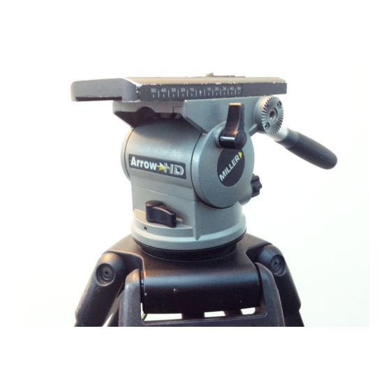
- Page 1 The Arrow Series Fluid Head Operator’s Manual #1020 Arrow 30 with Euro camera platform #1012 Arrow with Euro camera platform #1014 Arrow HD with Euro camera platform...
- Page 2 FEATURES AND CONTROLS 1/4” AND PIN ADAPTOR CARRIAGE Arrow 30 only SLIDING PLATFORM Arrow 30 and Arrow - 70mm range Arrow HD - 100mm range TILT LOCK TILT DRAG CONTROL BUBBLE LEVEL FIG 1 CAMERA SCREWS CAMERA PLATE QUICK RELEASE LEVER SAFETY TAB COUNTERBALANCE SELECTOR PAN DRAG CONTROL...
-
Page 3: Features And Controls
FEATURES AND CONTROLS PAN HANDLE TELESCOPIC CLAMP PAN HANDLE CLAMP SLIDING PLATFORM LOCK BOWL CLAMP NUT PAN LOCK FIG 2... -
Page 4: Table Of Contents
CONTENTS FEATURES AND CONTROLS SAFETY INSTRUCTIONS INTRODUCTION TECHNICAL DATA OPERATING INSTRUCTIONS 1. Install and level the Head 2. Mount Your Camera 3. Centre Your Camera on the Head 4. Counterbalance Your Camera 5. Drag Control 6. Illumination MAINTENANCE 7. Battery Replacement CLEANING STORAGE SPARE PARTS AND ACCESSORIES... -
Page 5: Technical Data
DATA Arrow 30 WEIGHT 3.2kg MAX REC. LOAD 15kg (see graph on Page 9) BALL LEVELLING BASE 100mm PAN MECHANISM Stepped Fluid Drag Adjustment 7 selectable positions + zero Rotation 360º Lock Calliper disc brake system TILT MECHANISM Stepped Fluid Drag Adjustment 7 selectable positions + zero + _ 90º... -
Page 6: Operating Instructions
OPERATING INSTRUCTIONS The Operating Instructions for Arrow series fluid heads are described in six (6) steps. Please read and understand these instructions before using this equipment. Do not omit any step. 1 INSTALL AND LEVEL THE HEAD 1.1 Unscrew the CLAMP NUT from its threaded stud. 1.2 Place the head in your 100mm tripod bowl and re-fit the CLAMP NUT. -
Page 7: Mount Your Camera
CAMERA PLATE CENTRE AXIS FIG 4 2 MOUNT YOUR CAMERA Arrow is equipped with a sliding platform for balance fine tuning, plus a quick-release camera plate and standard camera mounting screws (Arrow and Arrow 30 have 70mm sliding range, Arrow HD has 100mm sliding range). Please note that best camera control can be achieved by balancing the camera centre of gravity (C of G) over the centre axis of the head. -
Page 8: Centre Your Camera On The Head
2 MOUNT YOUR CAMERA Continued 2.5 Attach your camera to the fluid head by holding your camera slightly ‘lens down’ and place the attached CAMERA PLATE under the front lip on the top of the SLIDING PLATFORM. Lower the back of the camera until the QUICK RELEASE snaps automatically to the locked position. -
Page 9: Counterbalance Your Camera
4 COUNTERBALANCE YOUR CAMERA The Arrow 30, Arrow and Arrow HD include a variable counterbalance system that provides fingertip control through its tilt range and allows the camera to be set at any angle within that range. The counterbalance control can be set in one of four (4) positions depending on your camera payload. -
Page 10: Drag Control
5 DRAG CONTROL 5.1 Arrow heads provide seven (7) incremental settings for tilt and pan drag control as well as a zero (0) freewheeling position. There are no half stops. When changing drag settings, pan and tilt movements must be stopped. There is an endstop between Position 7 and Zero. -
Page 11: Battery Replacement
ILLUMINATION BUTTON BATTERY BATTERY DOOR FIG 7 7 BATTERY REPLACEMENT The Arrow illumination feature uses a standard long–life alkaline 12v battery. Under most operating conditions the battery will provide two years of operation. Miller approves use of the following batteries: Duracell MN21, Eveready A23, Vinnic L 1028. -
Page 12: Storage
#694 Email: sales@millertripods-europe.com #692 WEB SITE www.millertripods.com #684 P3836 #360 MILLER Camera Support (LLC) USA 216 Little Falls Road, Cedar Grove, New Jersey 07009-1231 USA Tel: (973) 857 8300 Fax: (973) 857 8188 Email: sales@millertripods.us MILLER TRIPODS Canada 1055 Granville Street...
Need help?
Do you have a question about the 1012 and is the answer not in the manual?
Questions and answers