Table of Contents
Advertisement
Quick Links
Advertisement
Table of Contents

Related Manuals for Miller Compass 25


Summary of Contents for Miller Compass 25
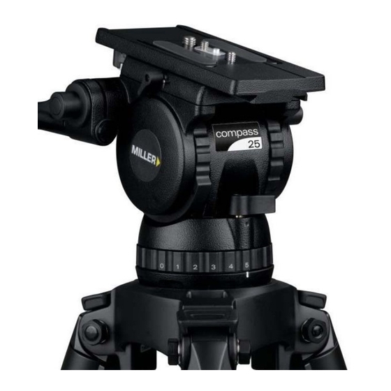
- Page 1 Fluid Head OPERATOR’S MANUAL #1038 Compass 25 Fluid Head...
-
Page 2: Features And Controls
Features and Controls Sliding Platform Sliding Platform Lock Pan Handle Clamp Tilt Lock Pan Lock Pan Handle Threaded Stud Clamp Nut... - Page 3 Features and Controls Camera Screws Camera Plate Release Knob Quick Release Knob Safety Tab Tilt Drag Control Accessory Mounting Counterbalance Selector Bubble Level Pan Drag Control Fig. 2...
-
Page 4: Safety Instructions
The robust design and construction of the Compass 25 Fluid Head secure and that the bowl is approximately horizontal when offers maximum stability, accuracy and durability and includes attaching the camera. -
Page 5: Technical Data
Technical Data Weight 2.8 kg 175 (6.9) 165 (6.5) Payload Range 4.0 – 14.0 kg 90 (3.5) Max.Payload Capacity 20 kg Tilt Drag 5 Selectable fluid drag positions + 0 Tilt Range + 90˚ / -75˚ Tilt Lock Positive Lock caliper brake system 102 (4.0) Pan Drag 5 Selectable fluid drag positions + 0... -
Page 6: Operating Instructions
Operating Instructions The operating instructions are described in six steps. Please read and understand these instructions before using this equipment. Do not omit any steps. Pan Handle Clamp F l u i d H e a d S e t - u p . Loosen the PAN HANDLE CLAMP fully then rotate the Pan Handle PAN HANDLE until it is approximately perpendicular to... - Page 7 Operating Instructions C a m e r a S e t - u p . 2.1 Remove the CAMERA PLATE by pulling down the SAFETY TAB while rotating the QUICK RELEASE KNOB to the left. The CAMERA PLATE should pop out. 2.2 Refer to the Camera’s owners manual for correct method of attachment to the CAMERA PLATE.
- Page 8 C o u n t e r b a l a n c e C o n t r o l The counterbalance system was designed to neutralise the Counterbalance Performance effect of the camera weight when it is tilted. The Compass 25 Fluid Head offers a 4 position counterbalance system which can be operated via the COUNTERBALANCE SELECTOR (fig.
- Page 9 P a n / T i l t D r a g C o n t r o l . The Compass 25 Fluid Head offers 5 selectable positions of fluid drag + zero setting in the Pan and Tilt. The settings are equally stepped...
-
Page 10: Maintenance
• B a t t e r y R e p l a c e m e n t . The Compass 25 Fluid Head uses a single 11A type - 6 Volt battery for Illumination. Miller recommends the following batteries to provide long life performance –... - Page 11 Service, Sales and Support Miller Authorised Service Agents must carry out all service and The Compass 25 Fluid Head can be stored for extended periods; repair work. Failure to observe this requirement may void Miller recommends storage in a Miller Soft Case and the following: warranty.
- Page 12 MILLER CAMERA SUPPORT EQUIPMENT 30 Hotham Parade Artarmon, Sydney, NSW 2064 Australia Tel: +61 2 9439 6377 Fax: +61 2 9438 2819 Email: sales@miller.com.au D7885-1...
Need help?
Do you have a question about the Compass 25 and is the answer not in the manual?
Questions and answers