Table of Contents
Advertisement
Quick Links
READ AND SAVE THESE INSTRUCTIONS
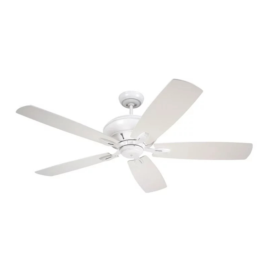
58" Ceiling Fan Owner's Manual
CF790BS00
Brushed Steel with
Walnut/Dark Mahogany Blades
CF790SW00
Satin White with
Satin White/Maple Blades
Questions, problems, missing parts: Before returning to the store call
Emerson Electric Customer Service 8 a.m. - 6 p.m., Eastern, Monday-Friday
Part No. F40BP74940000
Revision: 150610
CROFTON
Model Numbers
Net Weight:
1-800-654-3545
www.emersonfans.com
™
CF790VNB00
Venetian Bronze with
Walnut/Dark Mahogany Blades
CF790VS00
Vintage Steel with
Walnut/Riverwash Blades
25.5
Lbs.
• Español - página 29
• Français - page 57
Form No. BP7494
ETL Model No.: CF790
Advertisement
Table of Contents

Related Manuals for Emerson CROFTON CF790BS00


Summary of Contents for Emerson CROFTON CF790BS00
- Page 1 Satin White/Maple Blades 25.5 Net Weight: Lbs. Questions, problems, missing parts: Before returning to the store call Emerson Electric Customer Service 8 a.m. - 6 p.m., Eastern, Monday-Friday 1-800-654-3545 • Español - página 29 • Français - page 57 www.emersonfans.com Part No.
-
Page 2: Table Of Contents
Electric Co. Substitution of parts or accessories not 1. To avoid possible shock, be sure electricity is turned designated for use with this product by Emerson could off at the fuse box before wiring, and do not operate result in personal injury or property damage. -
Page 3: Unpacking Instructions
Fan Blade Flanges Emerson Electric Co. Substitution of parts or accessories not designated for use with this product Ceiling Fan Reversible Blades by Emerson Electric Co. could result in personal injury Hanger Bracket or property damage. Hanger Ball/4.5” Downrod Assembly... -
Page 4: Tools Needed For Assembly
WARNING Turning off wall switch is not sufficient. To avoid Please call Emerson technical support possible electrical shock, be sure electricity is turned off at the main fuse box before wiring. All wiring must 1-800-654-3545 if you have any questions about be in accordance with National and Local codes and installation and operation of this ceiling fan. -
Page 5: Ceiling Fan Assembly
3. Ceiling Fan Assembly WARNING Turning off wall switch is not sufficient. To avoid Disconnect electrical power to the branch circuit at the possible electrical shock, be sure electricity is turned off at the main fuse box before wiring. All wiring must circuit breaker or fuse box before attempting to install be in accordance with National and Local codes and the ceiling fan mounting plate on the outlet box. - Page 6 3. Ceiling Fan Assembly (Continued) Loosen the two setscrews in the motor coupling. Place the 4.5” downrod into the motor coupling, aligning the clevis pin holes in the downrod with the holes in the motor coupling (Figure 3). 4.5" DOWNROD HAIRPIN The clevis pin must go through the holes in the motor CLIP...
- Page 7 3. Ceiling Fan Assembly (Continued) 4.5" DOWNROD Place the ceiling cover over the downrod. Be sure both the ceiling cover and the coupling cover are oriented correctly (Figure 6). CEILING COVER Figure 6 4.5" DOWNROD NOTE: Only use the hanger ball supplied with this ceiling fan.
- Page 8 3. Ceiling Fan Assembly (Continued) 3.10 PARTIALLY ASSEMBLED Carefully turn the partially assembled ceiling fan over CEILING FAN and place it on the styrofoam for final preparation (Figure 9). STYROFOAM Figure 9 3.11 SHIPPING SPACER SCREW Remove the shipping spacers and the spacer SHIPPING SPACER attachment screws from the motor before installation of blade assemblies (Figure 10).
- Page 9 3. Ceiling Fan Assembly (Continued) 3.13 BLADE/FLANGE ASSEMBLIES (5) Loosely attach one blade/flange assembly to the motor 1/4-20 x 1/2" ROUND HEAD hub by securing the two 1/4-20 x 1/2” round head SCREWS WITH LOCKWASHERS (2 per blade/flange assembly) screws with lockwashers (Figure 12). MOTOR HUB Make sure the screws are NOT tightened.
- Page 10 Retain the screws for future use in Step 3.19. Spare #8-32 x 5/16” flat head screw is provided in parts NOTE: If you are using an Emerson light fixture bag if needed. with your fan. Remove the screw plug from the...
-
Page 11: How To Hang Your Ceiling Fan
4. How to Hang Your Ceiling Fan WARNING CEILING The fan must be hung with at least 7' of clearance from floor to blades (Figure 17). AT LEAST FLOOR Figure 17 WARNING The outlet box and joist must be securely mounted and capable of supporting at least 50 lbs. - Page 12 4. How to Hang Your Ceiling Fan (Continued) NOTE: SUPPLY WIRES AND FAN WIRES OMITTED FOR CLARITY. Carefully lift the fan and seat the hanger ball/ downrod assembly on the hanger bracket that was just OUTLET attached to the outlet box (Figure 19). Be sure the groove in the ball is engaged with the anti-rotation tab HANGER on the hanger bracket (Figure 19).
-
Page 13: How To Wire Your Ceiling Fan
Emerson Electric Co. Substitution of parts or WARNING accessories not designated for use with this product by Emerson Electric Co. could result in personal injury Turning off wall switch is not sufficient. To avoid or property damage. possible electrical shock, be sure electricity is turned off at the main fuse box before wiring. - Page 14 5. How to Wire Your Ceiling Fan (Continued) RECEIVER WHITE WIRE Securely connect the supply white (neutral) wire to the receiver white (AC IN N) wire using the wire connector SUPPLY (supplied) (Figure 22). WHITE WIRE (NEUTRAL) Securely connect the fan motor white wire to the receiver white (TO MOTOR N) wire using the wire connector (supplied) (Figure 22).
- Page 15 5. How to Wire Your Ceiling Fan (Continued) RECEIVER BLACK WIRE Wiring diagram of complete wiring of ceiling fan with RECEIVER RED RCFP receiver (supplied) (Figure 25). GROUND WIRE WIRE RECEIVER BLUE WIRE GREEN GROUND WIRE FROM HANGER BALL GREEN FAN MOTOR GROUND WIRE FROM...
-
Page 16: Wall Control Procedures
Code switches in the transmitter may be set in 32 different positions. If your fan and light turn on and Your Emerson Ceiling Fan/Light Control consists of off without using your control, you may be getting SW405 wall mounted transmitter and a receiver located interference from other remote units such as garage inside the motor assembly. -
Page 17: Wall Control Installation
7. Wall Control Installation SINGLE-POLE INSTALLATION WARNING CAUTION: To reduce the risk of electrical shock, Turning off wall switch is not sufficient. To avoid disconnect the electrical supply circuit before possible electrical shock, be sure electricity is turned installing the fan, light kit or receiver. off at the main fuse or circuit breaker box before wiring. - Page 18 7. Wall Control Installation (Continued) SCREWS (2) SW405 FAN/LIGHT Before installing the SW405 wall control, place the WALL WALL CONTROL SW405 wall control in “OFF” mode by pushing “ON/OFF” switch to the “OFF” position..Connect one black wire of the SW405 wall control to the “hot”...
- Page 19 LIGHT LIGHT CONTROL WALL WARNING FAN OFF PURCHASED CONTROL FAN OFF EMERSON ® EMERSON ® SEPARATELY BLACK Turning off wall switch is not sufficient. To avoid possible electrical shock, be sure electricity is turned LOAD off at the main fuse or circuit breaker box before TRAVELER wiring.
- Page 20 7. Wall Control Installation (Continued) 3-WAY WIRING DIAGRAM: NEW CONSTRUCTION NOTE: Retrofit 3-way installations are likely to STANDARD WIRING FOR EXISTING include two traveler wires between the two wall 3-WAY CONTROLS boxes. In new construction, only one traveler wire Is required (See Figure 32).
-
Page 21: Programming The Receiver Operating Frequency
8. Programming the Receiver Operating Frequency PROGRAMMING THE RECEIVER OPERATING FREQUENCY IMPORTANT: Ceiling fan blades MUST be installed If programming is unsuccessful, retry the above before high speed conditioning can begin. instructions after cycling the SW405 wall control ON/OFF switch to restart the 1 minute programming time period. -
Page 22: Using Your Ceiling Fan
9. Using Your Ceiling Fan WARNING USING YOUR CEILING FAN Fan installation must be completed, including the installation of the fan blades, before testing the SW405 Your SW405 wall control has full control of your fan and wall control. NOTE: Prior to operation of the ceiling fan and light light. -
Page 23: Maintenance
Emerson Electric Co. Substitution of parts or accessories not designated for use with this product The use of any other control not specifically approved by Emerson Electric Co. could result in personal injury for this fan could result in fire, shock and personal or property damage. -
Page 24: Repair Parts
13. Repair Parts ....PARTS BAG ETL Model No.: CF790... -
Page 25: How To Order Repair Parts
13. Repair Parts Listing Model Numbers Description CF790BS00 CF790SW00 CF790VNB00 CF790VS00 Hanger Ball Assembly, Consisting of: 761655-17 761655-92 761655-89 761655-93 Hanger Bracket (1) — — — — Hanger Ball (1) — — — — 4.5” Downrod Assembly (1) — — —... -
Page 26: Trouble Shooting
14. Trouble Shooting WARNING: FOR YOUR OWN SAFETY TURN OFF POWER AT FUSE BOX OR CIRCUIT BREAKER BEFORE TROUBLE SHOOTING YOUR FAN. TROUBLE PROBABLE CAUSE SUGGESTED REMEDY 1. Fan will not start. 1. Reversing switch in neutral position. 1. Make sure reversing switch position is all the way to one side. -
Page 27: Ceiling Fan Limited Warranty
What We Will Do To Correct Problems: If during the one (1) year warranty period the motor or any component or accessory of your Emerson Ceiling Fan is defective in materials or workmanship, or if during the expected lifetime of the Emerson Ceiling Fan (when used in accordance with the User Manual or other instructions) the motor is defective in materials or workmanship, you must contact Emerson during the applicable warranty period. - Page 28 Air Comfort Products DIVISION OF EMERSON ELECTRIC CO. 8100 W. Florissant • St. Louis, MO 63136 Questions, problems, missing parts: Before returning to the store call Emerson Electric Customer Service 8 a.m. - 6 p.m., Eastern, Monday-Friday 1-800-654-3545 www.emersonfans.com Retain this manual for future use.
Need help?
Do you have a question about the CROFTON CF790BS00 and is the answer not in the manual?
Questions and answers