
Related Manuals for AstroJet M1


Summary of Contents for AstroJet M1
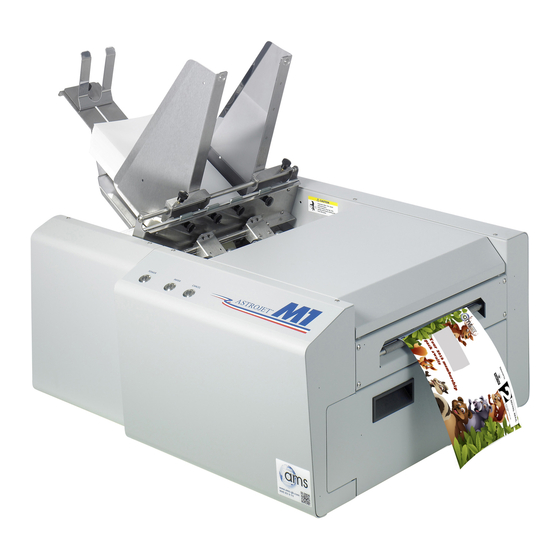
- Page 1 AstroJet COLOR PAGE PRINTER OPERATOR MANUAL ASTRO MACHINE CORP. 630 Lively Blvd. Elk Grove Village, IL 60007 Phone: (847) 364-6363 Fax: (847) 364-9898 www.astromachine.com...
-
Page 2: Safety Precautions
SAFETY PRECAUTIONS THIS EQUIPMENT PRESENTS NO PROBLEM WHEN USED PROPERLY. HOWEVER, CERTAIN SAFETY RULES SHOULD BE OBSERVED WHEN OPERATING THE ASTROJET M1 PRINTER. BEFORE USING THE PRINTER, YOU SHOULD READ THIS MANUAL CAREFULLY AND FOLLOW THE RECOMMENDED PROCEDURES, SAFETY WARNINGS, AND INSTRUCTIONS: ... -
Page 3: Table Of Contents
Install the Ink Tanks Install the Printhead Cartridge Removing the Head Media Guide Install/Remove Envelope Attachment Spacers Setting up the Feed SECTION 3 – Operating the M1 Printer Setting Up a Job in MS Word Printer Driver Properties General Tab Layout Tab... - Page 4 TABLE OF CONTENTS NOTES ______________________________________________________ ______________________________________________________ ______________________________________________________ ______________________________________________________ ______________________________________________________ ______________________________________________________ ______________________________________________________ ______________________________________________________ ______________________________________________________ ______________________________________________________ ______________________________________________________ ______________________________________________________ ______________________________________________________ ______________________________________________________...
-
Page 5: Section 1 - Getting Acquainted
SECTION 1 GETTING ACQUAINTED SECTION 1 – Getting Acquainted Front View Cancel LED Button – Cancels the job being printed. Paper LED Button – Press to stop printing, press to restart printing. Press switch to continue printing. ON/OFF LED Button – Use to turn power ON or OFF during idle time and maintenance. -
Page 6: Rear View
SECTION 1 GETTING ACQUAINTED Rear View Main Power Switch, Receptacle and Fuse – Plug in power cord here. Switch turns main power ON/OFF. (Use the Control Panel LED Power switch to turn off machine for cleaning and maintenance). Fuse protects the Printer’s electronic circuits. USB Port Connection –... -
Page 7: Print Engine View
SECTION 1 GETTING ACQUAINTED Print Engine View Printhead Latch – When closed, connects the Ink Revolver Couplings with the Printhead Cartridge. When opened, retracts the Ink Couplings from the Printhead Cartridge and provides access to the Printhead Cartridge for cleaning and replacement. WARNING! Never attempt to open the Printhead Latch manually, severe damage will result. -
Page 8: Ink Tank Door View
SECTION 1 GETTING ACQUAINTED Ink Tank Door View Ink Tank Securing Latches – Used to hold the Ink Tanks in the slots. NOTE: Please be sure that both sides at the bottom part of the latch are engaged. Ink Tanks – Printer has 5 Ink Tanks: Cyan, Yellow, Magenta, Black, Black Ink Waste Tray –... -
Page 9: Control Panel Button/Led Indicators
SECTION 1 GETTING ACQUAINTED Control Panel Button/LED Indicators The Control Panel has 3 buttons with LED indicators. POWER (ON/OFF) – Turns Printer power ON and OFF. Turn off power for cleaning and maintenance PAPER (STOP JOB/RESUME) – Stops Paper Feed or Resumes Printing. -
Page 10: Section 2 - Installing The Printer
SECTION 2 INSTALLING THE PRINTER SECTION 2 – Installing the Printer Contents of Packaging M1 Printer Ink Tanks – Cyan, Magenta, Yellow, Black, Black Printhead Cartridge Media Side Guides: Registration (Fixed) and Adjustable – mounting screws attached to Printer Rear Media Support Guide –... -
Page 11: Remove Service Station Transport Tab And Shipping Tape
SECTION 2 INSTALLING THE PRINTER Remove Service Station Transport Tab and Shipping Tape 1. Open the Top Cover. 2. Release the two latches (one on either side of the Print Engine). Open the top half of the Clamshell by lifting both levers at the same time. CAUTION HOLD ONTO BOTH LATCHES WHEN OPENING AND CLOSING THE PRINT ENGINE CLAMSHELL TO PREVENT DAMAGE. -
Page 12: Assembling The Printer
SECTION 2 INSTALLING THE PRINTER Assembling the Printer Install the Adjustable Side Guide with two screws [1]: Install the Envelope/Paper Side Guide with the two screws [2] provided. Attach the Rear Paper Support using the knob [3] provided. NOTE: The two outside holes fit over the socket head screws. Install the Rear Guide using the thumbscrew and washer [4] provided. -
Page 13: Connecting The Printer
SECTION 2 INSTALLING THE PRINTER Connecting the Printer Plugging in the Printer Plug the power cord into the receptacle [1] at the rear of the Printer. The internal power supply in the Printer is rated 115 to 240VAC, 50/60 Hz. CAUTION DO NOT USE AN ADAPTER PLUGS OR EXTENSION CORDS TO CONNECT THE PRINTER TO THE WALL RECEPTACLE. -
Page 14: Install The Printer Driver
SECTION 2 INSTALLING THE PRINTER Install the Printer Driver For the Printer software to operate properly check that the computer system meets these minimum requirements: Operating System: Windows XP, Windows Vista, Windows 7, Windows 8/8.1. Supports 32 and 64 bit systems. - Page 15 SECTION 2 INSTALLING THE PRINTER 3. License Agreement. Check “I accept…” then click “Next>”. 4. Printer Connections. Click “Configure to print using USB”. Then click “Next>”. 5. Installing Printer Software. Software download begins. 6. Would You Like to Install This Device Software? Click “Install”.
-
Page 16: Install The Ink Tanks
SECTION 2 INSTALLING THE PRINTER 8. Finished software installation. Do not check the Print Test Page as the Printer is not set up yet. You can check the “Set this printer as the default printer” at this time. Click “Next>”. 9. - Page 17 SECTION 2 INSTALLING THE PRINTER 3. Open the Ink Tank Door (hinged at bottom). Open the three Latches [A]. 4. Remove the Ink Tank(s) from packaging. 5. Insert the Ink Tanks (labels up) into their appropriate color slots [B]. Close the three Ink Tank Latches.
-
Page 18: Install The Printhead Cartridge
SECTION 2 INSTALLING THE PRINTER Install the Printhead Cartridge The Printhead Cartridge is a delicate precision device. Handle with extreme care to avoid damage and issues that could degrade print quality. CAUTION Use electrostatic discharge (ESD) protection when handling. ... - Page 19 SECTION 2 INSTALLING THE PRINTER 2. [A] Carefully remove the Printhead Cartridge from the foil packaging. Tear at notch or cut end with scissors. [B] Remove the protective plastic cover. Hold the Printhead by the handle and unclip the cover from the Printhead. [C] Remove protective strip from the Printhead Electrical Contacts.
- Page 20 SECTION 2 INSTALLING THE PRINTER 4. Wet the Printhead Surface. This ensures that the Printhead will prime correctly. Open the Top Cover. Release and lift the two latches at the same time to raise the Print Engine Clamshell. Moisten the Printhead nozzles using distilled water and a damp, lint-free cloth, wiping end to end.
-
Page 21: Removing The Head Media Guide
SECTION 2 INSTALLING THE PRINTER Removing the Head Media Guide You can remove the Head Media Guide if you are primarily printing on thin, flat stock (that is, you are not printing large batches of envelopes) and are encountering print quality issues. The attachment is used to flatten the envelope flap for better print consistency. -
Page 22: Install/Remove Envelope Attachment Spacers
SECTION 2 INSTALLING THE PRINTER Install/Remove Envelope Attachment Spacers Install the Envelope Attachment Spacers if you are printing large volumes of envelopes. Remove the Spacers if you are primarily printing sheet stock. DO NOT use the spacers without the Envelope Attachment (Head Media Guide). -
Page 23: Setting Up The Feed
SECTION 2 INSTALLING THE PRINTER Setting up the Feed The Printer is equipped with four Sheet Separators, two Side Guides and a Rear Media Guide. The Sheet Separators are adjusted individually as follows: 1. Move the Left-hand Side Guide into position. This Guide has two positions. The position closest to the Side Frame is for 9.5"... - Page 24 SECTION 2 INSTALLING THE PRINTER 4. Adjust the Right-hand Side Guide so that it is about 1/32-inch from the sides of the media. Tighten the locking knob on the Side Guide. Place a stack of media in the machine. Press and hold the Paper key to feed one piece through the Separator.
-
Page 25: Section 3 - Operating The M1 Printer
SECTION 3 OPERATING THE ASTROJET M1 SECTION 3 – Operating the M1 Printer Once the Printer Driver is installed on your computer and the Printhead is primed, you are ready to start printing. Set up your job and send it to the Printer. The Printer will start and print. - Page 26 SECTION 3 OPERATING THE ASTROJET M1 Printing a Typical Job on 8.5-inch by 5.5-inch Paper The Printer can print edge-to-edge on an 8.5" x 5.5" document. Follow these steps to set up a job: 1. Go to File, then Page Setup and select 0" margins.
-
Page 27: Printer Driver Properties
SECTION 3 OPERATING THE ASTROJET M1 Printer Driver Properties The Printer Driver for the Printer works the same as any other Printer Driver for Windows. It does have some enhancements to help you maximize the ability of the Printer to print variable addressed pieces quickly and efficiently. -
Page 28: Layout Tab
SECTION 3 OPERATING THE ASTROJET M1 Media – Choose a type of media or MEDIA PROFILE MEDIA TYPE different size media than the Plain Paper document was originally designed Plain Paper Bright White Paper for. Type: Chart at right lists the... - Page 29 SECTION 3 OPERATING THE ASTROJET M1 Using Layout Tab Printing Adjustments Image Position – Left Adjustment moves the image area away (-3mm left to +200mm right) from the left edge of the media. Top Adjustment moves the image up or down (-5mm up to +200mm down) from the top left corner of the media used.
-
Page 30: Import/Export Tab
SECTION 3 OPERATING THE ASTROJET M1 Import/Export Tab Import/Export is used to preserve any custom Media Sizes, Watermarks and/or Print Settings you may have developed and saved for various jobs when you update the Printer firmware. Export – Send the custom settings to a holding file before downloading the new firmware. -
Page 31: Using The Printer Toolbox
SECTION 3 OPERATING THE ASTROJET M1 Using the Printer Toolbox Once the Printer Driver is installed you have access to the Printer Toolbox. The Toolbox lets you check printer status, monitor ink usage, perform diagnostic checks, print reports and run maintenance tasks on the Printer from your computer. - Page 32 SECTION 3 OPERATING THE ASTROJET M1 [B] SETUP Settings – Let you adjust automated service and cleaning intervals, adjust the feeder speed for a job, manually set the gap between pieces and adjust the Printer for pre-printed media. KWS Setting – (Keep Wet Spitting) Keeps Printhead hydrated while running a job.
- Page 33 SECTION 3 OPERATING THE ASTROJET M1 [C] SERVICE buttons control functions that require the machine to be out of service for extended periods of time while they are being performed. Replace Ink Tanks – Disconnects Printer communication with Ink Tank Sensor.
- Page 34 SECTION 3 OPERATING THE ASTROJET M1 [E] Firmware Download – Get the latest version of firmware for your Printer. NOTE: This is an alternative method for downloading the firmware. See “Updating Firmware” for the recommended procedure. WARNING: This procedure should only be performed by qualified service personnel.
-
Page 35: Ink Usage
SECTION 3 OPERATING THE ASTROJET M1 Ink Usage Allows you to monitor the estimated amount of ink left in each of the five Ink Tanks. You can monitor ink use and consumption and schedule Tank changes (saving down-time during a print run.) NOTE: Ink Usage only... -
Page 36: Service Menu
SECTION 3 OPERATING THE ASTROJET M1 2. The “Network Configuration” page opens. Use Network Settings to enter the correct settings for your network. 3. Connect Ethernet cable to Network Port on Rear Panel of Printer. Service Menu For authorized personnel only. Provides access to more advanced Printer control and maintenance menus. -
Page 37: Updating Firmware
SECTION 3 OPERATING THE ASTROJET M1 Updating Firmware Get the latest version of firmware for your Printer. NOTE: Use this procedure to update the firmware AFTER you have updated the Printer Driver. The Printer Driver update procedure is included with an “Update Package”... -
Page 38: Section 4 - Maintenance
SECTION 4 MAINTENANCE SECTION 4 – Maintenance General, periodic maintenance is needed to keep the Printer in good working order. This section covers how to care for the Ink Tanks, Printhead Cartridge, Service Station, and clear paper jams. Replacing the Ink Tanks Replace the Ink Tanks when the ink runs out. -
Page 39: Cleaning Ink Tank Contacts
SECTION 4 MAINTENANCE 6. Click “Continue” on the Confirm screen, then “Refresh Ink Levels” on the User Interface screen. The ink colors fill in as the Ink Tanks are installed. If the ink colors do not fill in after a few seconds, click “Replace Ink Tanks”... - Page 40 SECTION 4 MAINTENANCE 2. Open the Front Cover, release the Ink Tank Latch(es) [A] and remove the Ink Tank(s) [B] that did not refresh. 3. Clean the Ink Level Prism [A] and QA Chip contacts [B] with a clean, dry, lint-free cloth. NOTE: You can dampen the cloth with distilled water to wipe the Prism, but DO NOT get the QA Chip contacts wet.
-
Page 41: Cleaning/Replacing The Printhead Cartridge
SECTION 4 MAINTENANCE Cleaning/Replacing the Printhead Cartridge Cleaning The Printhead in the Printer is cleaned automatically each time the machine is turned on or when the “Quick Clean Printhead” routine is performed by the operator. This can be found under the Service Tab, “Quick Clean Printhead”... - Page 42 SECTION 4 MAINTENANCE Replacing the Printhead Cartridge 1. Open the Toolbox. On the User Interface screen System Status information appears in the upper left corner. 2. Open the Top Cover. Press the Printhead Latch Release button [1]. The Printer pumps any ink in the system back into the Tanks.
- Page 43 SECTION 4 MAINTENANCE 4. [A] Carefully remove the Printhead Cartridge from the foil packaging. Tear at notch or cut end with scissors. [B] Remove the protective plastic cover. Hold the Printhead by the handle and unclip the cover from the Printhead. [C] Remove protective strip from the Printhead electrical contacts.
- Page 44 SECTION 4 MAINTENANCE 7. Wet the Printhead Surface. This ensures that the Printhead will prime correctly. Open the Top Cover. Release and lift the two latches at the same time to raise the Print Engine Clamshell. Moisten the Printhead nozzles using distilled water and a damp, lint-free cloth, wiping end to end.
-
Page 45: Printhead Service Life
SECTION 4 MAINTENANCE Printhead Storage Store and transport the cartridge as indicated by the "this side up" arrow symbol on the packaging. The cartridge and ink supply must be within the operating temperature range before attempting to prime the cartridge with ink and starting to print. - Page 46 SECTION 4 MAINTENANCE Return Procedure: 1. Verify eligibility for return. Check the page count printed by this Printhead, if the page total is more than 40,000 pages, the replacement policy does not apply. NOTE: This is NOT the Printer page count. Make sure the Printer is powered up and connected via USB or network.
-
Page 47: Replacing The Service Station
SECTION 4 MAINTENANCE Replacing the Service Station The Service Station (located above the Ink Tank Station) cleans the Printhead Cartridge of excess ink and debris, keeps the Printhead hydrated and protected when not in use, captures ink used to keep nozzles clear, and acts as a base to support media during printing. - Page 48 SECTION 4 MAINTENANCE 3. Carefully slide the Service Station out of the Service Station port. NOTE: DO NOT pull the Service Station all the way out until you disconnect the Ribbon Cable. USEFUL TIP: Place an absorbent towel under the Service Station before you remove it to catch any drips or leaks.
- Page 49 SECTION 4 MAINTENANCE 6. Slide the Latch open on the Service Station Circuit Board. 7. [1] Plug the Ribbon Connector (blue side up) into the space under the Latch. [2] Close the Latch. 8. [1] Slide the Service Station into the Service Station port until it touches the bar. Align with tracks along sides and Guide on Service Station dock floor.
- Page 50 SECTION 4 MAINTENANCE 9. GENTLY push the Service Station while turning the large Gear on right side of Print Engine clockwise. Gear should engage gear on Service Station Roller and pull it in. Once the Service Station starts moving, stop turning the gear. 10.
-
Page 51: Replacing The Ink Waste Tray
SECTION 4 MAINTENANCE Replacing the Ink Waste Tray The Ink Waste Tray soaks up any excess ink that may drip from the Print Engine during operation. After a period of time it may become saturated and need replacement. 1. Open Ink Tank Door. 2. -
Page 52: Jams In The Printer
SECTION 4 MAINTENANCE Jams in the Printer If a jam occurs, STOP the Printer. Some possible causes for jamming are: 1. Feeding more than one piece of media (double-feeding). 2. Damaged media, such as dog-eared (turned down corners). 3. Media that is not stiff enough may not be usable. Media that meets Postal stiffness requirements for automated feeding is acceptable in the Printer 4. -
Page 53: Cleaning
SECTION 4 MAINTENANCE Cleaning WARNING! THE PRINTER IS A PRECISION MACHINE. CLEAN REGULARLY TO INSURE MANY YEARS OF SERVICE. BEFORE PERFORMING ANY MAINTENANCE, DISCONNECT THE MACHINE FROM ITS POWER SOURCE! DO NOT REMOVE SIDE COVERS! HIGH VOLTAGES PRESENT. Clean the Printer regularly to remove accumulated paper dust and ink. Depending on the types of media that are run, paper dust may accumulate inside the Printer and on the Transport. -
Page 54: Print Engine
SECTION 4 MAINTENANCE Print Engine Areas in the Print Engine can become glazed with a buildup of dust, paper lint and accumulated ink and have to be cleaned regularly. Open the Top Cover. Open the Clamshell Assembly by releasing the two latches. -
Page 55: Shipping Or Transporting The Printer
SECTION 4 MAINTENANCE Shipping or Transporting the Printer If you have to ship or transport the Printer for any reason, the unit will have to be prepared. Once the Printer is prepared, carefully package the Printer, Printhead Cartridge, Service Station and Ink Tanks in their original packaging. - Page 56 SECTION 4 MAINTENANCE Remove the Service Station 1. Open the Front Cover (hinged at bottom). Open the Top Cover. Release the two latches and open the Print Engine Clamshell. The Service Station will not fully eject with the Clamshell closed. 2.
- Page 57 SECTION 4 MAINTENANCE Disconnect the Ribbon Cable. Slide the Latch open on the Service Station Circuit Board to release the Ribbon Cable. Remove the Service Station. Remove the Ink Tanks 1. Open the Front Cover (hinged at bottom). Unlatch the three Locks [A] and pull the Ink Tank(s) out of the Printer.
-
Page 58: Section 5 - Troubleshooting Guide
SECTION 5 TROUBLESHOOTING SECTION 5 – Troubleshooting Guide The following Troubleshooting Guides are provided to assist you in solving any problems that might occur with the Printer. We have tried to make them as complete as possible. The best advice we can offer is to make sure that the system is set up properly, plugged in, and that it has an adequate supply of ink before attempting to troubleshoot any problem. -
Page 59: The Printer
SECTION 5 TROUBLESHOOTING The Printer CONDITION PROBLEM SOLUTION Ink Tank installed, no Ink Ink Tank contacts dirty, Remove Ink Tank(s). Clean prism Level indication in Toolbox preventing Printer/Ink Tank and QA Chip contacts, see communication. Maintenance, Cleaning Ink Tank Contacts. Extra lines;... -
Page 60: Errors And Warnings
SECTION 5 TROUBLESHOOTING Errors and Warnings Printer Alert Window Messages Messages sent from the driver and displayed on PC screen in a small popup window. MESSAGE SOLUTION Wait until the message disappears. The Printer will start printing your job once Cleaning in Progress the cleaning process is complete. -
Page 61: Toolbox System Status Messages
SECTION 5 TROUBLESHOOTING Toolbox System Status Messages Displayed in in the M Series Toolbox utility. (Valid for printers with firmware version 20130820 or higher installed.) SYSTEM STATUS SOURCE SOLUTION Out of Paper Load media into Printer and press the PAPER button to Media is not reaching resume printing. - Page 62 SECTION 5 TROUBLESHOOTING Toolbox System Status Messages (Continued) SYSTEM STATUS SOURCE SOLUTION X = Color. Replace empty Ink Tank(s), using the “Replace Ink Tanks” One or more Ink command from EWS. Tanks are out of ink. Verify that the Ink Tanks are seated firmly and the latches are fully closed.
- Page 63 SECTION 5 TROUBLESHOOTING Toolbox System Status Messages (Continued) SYSTEM STATUS SOURCE SOLUTION Mechanical error Visually inspect the component stated as a “Reason” for failure. One of the Printer's mechanical Using the Scan Sensors page in components was not the Toolbox, perform the toggle properly registered at test on the Sensor responsible the expected position.
- Page 64 SECTION 5 TROUBLESHOOTING Toolbox System Status Messages (Continued) SYSTEM STATUS SOURCE SOLUTION Printhead missing and Install Printhead. one or more of the Ink Install Ink Tanks. Tanks are missing. When this error occurs, Multiple EWS monitoring is disabled. No Printhead installed If the Printer was just powered or Printhead not on, wait a minute;...
-
Page 65: Appendices
APPENDICES Appendix A – AstroJet M1 Specifications Best: 1600 x 1600 DPI PRINT RESOLUTION Normal: 1600 x 800 DPI SPEED Up to 3600 letter size pages or 9000 envelopes per hour (color or mono) Minimum: 3" x 4.2" (76 mm x 107 mm) MEDIA SIZE Maximum: 9.5"... -
Page 66: Index
INDEX #10 Envelope Setup 9.5" x 17" Paper Setup Head Media Guide Adjustable Media Guide 1, 2, 8 Import/Export Tab, Printer Driver Assembling Printer Indicators, Control Panel Button Ink Revolver Couplings Cancel Button Ink Revolvers Cartridge, Printhead Ink Tanks Choose Location Cleaning Contacts Clamshell Latches Disposal... - Page 67 INDEX Troubleshooting Package Contents Paper Button Rear Guide 1, 2, 8 Power Button Rear Guide Support 1, 2, 20 Power Connection Rear Paper Support Print Engine Receptacle, Power Cleaning Remove/Replace Ink Revolvers Envelope Attachment Print Ink Channels Envelope Attachment Spacers Printhead Release Button Head Media Guide Service Station...
- Page 68 INDEX Unpacking USB Port 2, 9, 11 User Interface, Toolbox Using Printer Toolbox Warning Messages...
-
Page 69: Printer Maintenance Schedule
PRINTER MAINTENANCE SCHEDULE General, periodic maintenance is needed to keep the Printer in good working order. Many tasks can be performed by operators with basic supplies, no special tools needed. Other tasks should only be performed by trained service personnel. NOTE: High volume usage may require more frequent maintenance. Maintenance Supplies &... - Page 70 NOTES ______________________________________________________ ______________________________________________________ ______________________________________________________ ______________________________________________________ ______________________________________________________ ______________________________________________________ ______________________________________________________ ______________________________________________________ ______________________________________________________ ______________________________________________________ ______________________________________________________ ______________________________________________________ ______________________________________________________...
-
Page 71: Control Panel Led Sequences
Control Panel LED Sequences Print and cut out this chart to mount on the printer if desired. Suggested location: Top Cover. - Page 74 Copyright © 2014 ASTRO MACHINE CORP. Elk Grove Village, IL 60007 12/02/2014 Part Number: 200-M1, Rev. T...
Need help?
Do you have a question about the M1 and is the answer not in the manual?
Questions and answers