
Related Manuals for Abus TVVR50011


Summary of Contents for Abus TVVR50011
-
Page 1: User Manual
ABUS Digital Recorder TVVR50011 / TVVR50021 TVVR60010 / TVVR60020 User manual Version 1.4... - Page 2 A list of contents with the corresponding page number can be found in the index. Pay attention to the information in the separate quick guide, plus the notes on the CD and in the ac- companying documentation on “Web server control” and “Clients Software”. These can be found on the Internet under www.abus-sc.com.
-
Page 3: Device Overview
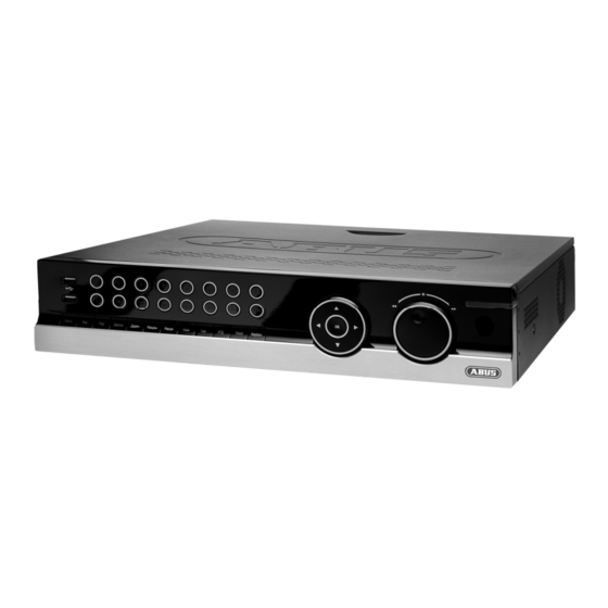
Device overview Device overview See System operation on page 13. Front Rear The diagram shows the TVVR50021 version with 16 channels. The models TVVR50011, TVVR60010 and TVVR60020 are similar. - Page 4 Device overview Remote control (TVAC40930 optional available)
-
Page 5: Table Of Contents
Contents Device overview ................................3 Quick guide..................................8 Before you start ................................8 Installing the HDD ................................8 Establishing the connections ............................8 Configuring the device ..............................8 Important safety information ............................9 Explanation of symbols ..............................9 Proper use ..................................9 General information ................................. - Page 6 Contents Digital Zoom ................................22 Secondary monitor ..............................22 System Settings ................................23 Setting the camera output............................23 Record Settings ................................24 Set-up..................................... 24 General settings ................................ 24 Advanced settings ..............................24 Schedule ................................... 25 Manual Record ................................25 Playback ..................................26 General information ...............................
- Page 7 Contents System Settings: RS232 ............................43 System Settings: Display ............................43 System Settings: Exception ............................44 System Settings: User .............................. 44 System Settings: UVV .............................. 45 Maintenance .................................. 46 Upgrading the device ..............................46 Log Search ................................47 Default Settings ................................ 48 Import / Export Configuration ............................
-
Page 8: Quick Guide
Note Check that the connections are secure. Check that the connections are secure. Check the ABUS homepage ( Check the ABUS homepage (www.abus- Close the housing. sc.com) if for this device any firmware updates ) if for this device any firmware updates... -
Page 9: Important Safety Information
Important safety information Important safety information Important safety information Important safety information Explanation of symbols General information The following symbols are used in this manual and on the The following symbols are used in this manual and on the Before using the device for the first time, read the follo Before using the device for the first time, read the follow- device: ing instructions carefully and pay attention to all war... -
Page 10: Overloading / Overvoltage
Important safety information To avoid the possibility of fires, the plug should a To avoid the possibility of fires, the plug should al- Installation location / operating enviro / operating environ- • ways be disconnected from the network socket if the onnected from the network socket if the ment device is not used for long periods. -
Page 11: Care And Maintenance
Important safety information Important safety information Care and maintenance Putting into operation Maintenance is necessary if the device has been da sary if the device has been dam- Observe all safety and operating instructions before Observe all safety and operating instructions before •... -
Page 12: Introduction
ABUS S at any time and without prior warning. ABUS Se- curity-Center GmbH is not liable or responsible for... -
Page 13: System Operation
System operation System operation Name General information Function The device can be controlled as follows: Camera selection keys (1, 2, 3...): Using the operating elements on the front of the de- • Displays the camera status: vice • White: Camera is connected Using the remote control •... -
Page 14: Connections On The Rear Of The Device
System operation Connections on the rear of the device Operating elements on the remote control Note Note Pay attention to the overview on page 3. Pay attention to the remote control diagram on page 4. Name Function Name Function VIDEO SPOT OUT: BNC video output DEV: When using a HDMI/VGA monitor: •... -
Page 15: Mouse Operation
System operation Name Mouse operation Function Note Not used Further descriptions in these operating instruc- Not used tions are made with the mouse. Zoom +: Zooms in on the image section in PTZ mode The device is suitable for use with a USB mouse. Connect the mouse to the USB port. -
Page 16: On-Screen Keyboard
System operation On-screen keyboard Switching off, locking and rebooting the , locking and rebooting the The on-screen keyboard appears after clicking on a text screen keyboard appears after clicking on a text device entry field with the mouse: Click on “ShutDown” in the main menu own”... -
Page 17: Status Displays
Status displays Status displays Camera selection keys – status LED General information State Function The following status displays indicate the current operat- Off: No camera connected ing state: White (constantly lit): Camera is connected LEDs on the front of the device •... -
Page 18: Setup Wizard
Setup wizard Setup wizard Setting up the system Setting up the administrator Setting up the administrator The setup wizard guides you through the necessary b The setup wizard guides you through the necessary ba- Warning sic system settings. The DVR is then set up for recording sic system settings. -
Page 19: Hdd Management
Setup wizard To transfer this schedule to other cameras, first s To transfer this schedule to other cameras, first se- HDD Management lect the camera (or “All” if all cameras should have lect the camera (or “All” if all cameras should have Click on “Enter”. -
Page 20: Camera Management
Setup wizard Camera Management Note Click on Enter. You can edit all of the settings after exiting the wizard. To do this, open the menu (see page 32). Click on Status. The camera overview opens. Deactivate the analogue camera inputs by uncheck- ing the boxes. -
Page 21: Live View
Live view Live view Status symbols Overview The following symbols are displayed depending on The live view starts automatically after the device is • the operating status of the device: switched on. Symbol Meaning You can also go back to the live view by pressing the Event detected Menu key repeatedly. -
Page 22: Digital Zoom
Live view Secondary monitor Single Camera Full-screen view for selected camera Multi Camera Various camera layouts The secondary monitor is used to display a different view to that on the main monitor. The Switch Monitor com- Next Screen Displays the next camera(s) mand is used to switch from the main monitor to the sec- Stop Auto- Starts the camera sequence... -
Page 23: System Settings
Live view Setting the camera output System Settings Up to 16 cameras can be set simultaneously in the live Note view. The live view can be set as follows. Click on “Set”. Open the main menu, then click on “System Settings” and then “Display Settings”: Select the display mode. -
Page 24: Record Settings
Record Settings Record Settings More Settings Set-up Detailed settings Pre-alarm Recording period before an alarm Open the main menu, then click on “System Settings” (in seconds) and then “Record Settings”: Post-alarm Recording period after an alarm (in seconds) Expiration Period (in days) after which the re- cording is deleted automatically at 00:00. -
Page 25: Schedule
Record Settings Specify the recording type in the drop-down menu: Schedule Normal • The schedule is used to specify the recording times and triggers (recording type) for the cameras. Click on the Motion detection • “Schedule” tab: Alarm • Motion detection or alarm •... -
Page 26: Playback
Playback Playback Fast-forward General information Slow-motion advance Playback can be made in three different ways: Next recording / day Through the video search in the main menu • Time bar: From the live view • Click on the time bar with the mouse to con- •... -
Page 27: Playback: Advanced Video Search
Playback The following settings are available: Playback from the live view screen Camera Camera to be set Click on playback whilst the live view screen is shown: Video Type Schedule, motion detection, alarm or mo- Playback is controlled on the control panel: tion detection and/or alarm, manual re- cording, all File Type... -
Page 28: Ptz Control
In order to open the menu of ABUS PTZ- • Cameras enter Preset 95. By using the naviga- tion buttons you can move within the menu. -
Page 29: Ptz Settings
Exit the settings by pressing “Apply” and “OK”. Exit the settings by pressing “Apply” and “OK”. Note Note When using ABUS PTZ-Cameras with the Pelco- Compare the settings with the technical data of D protocol some presets are predefined and can- the connected camera. -
Page 30: Tour Settings
PTZ control Call a tour set in the PTZ-Camera Tour Settings You can also configure tours directly in the camera. The Patrols are defined tours from position to position that are advantage is that other control devices, e.g. keyboard, accessed in sequence on the PTZ camera. The individual can call the tours as well. -
Page 31: Pattern Settings
PTZ control Pattern Settings Patterns are defined tours from position to position that are accessed in sequence on the PTZ camera. Patterns are recorded live. The system saves the parameters used whilst you move and adjust the cameras in se- quence to the corresponding positions at a defined speed. -
Page 32: Device Menu
Device menu Device menu Menu overview When the mouse cursor is pointed at a menu, it is • marked and a short description of the menu is shown The following overview shows all menus used to set and at the bottom. control the device. -
Page 33: Manual Record
Device menu Manual Record Video Search Note Parameters for Video Search Only active cameras can be selected for manual “General” tab recording. Analog Overview of analogue cameras The recording starts immediately. Used for searching the selected cameras Select the camera by checking the corresponding box. -
Page 34: Results
Device menu Results Set the parameters that should be used for search- ing for a recording. After making a search, the results screen is displayed: When searching in the “General” tab, you can open the overview by pressing “Details”: Highlight the searched recording. •... -
Page 35: Video Export
Device menu Video Export 4. Click on Export to access the export screen. Note Select the connected medium used for data storage from the drop-down menu. The export function is used to store important re- cordings on connected external media, such as: If the medium is not displayed, click on Refresh. -
Page 36: Manual Alarm
Device menu Manual Alarm HDDs Note The device manages up to eight 3.5" SATA hard up to eight 3.5" SATA hard disk drives. Each of the installed HDDs must be initialised b Each of the installed HDDs must be initialised be- fore the device can be used for fore the device can be used for recording. -
Page 37: Initialising The Hdd
Device menu Initialising the HDD Note If the initialised HDD is not displayed, check the connections. Select the HDD by checking the corresponding box. Start the process by clicking on “Init”. Confirm the prompt by pressing OK. The status bar shows the progress of the initialisa- tion. -
Page 38: Adding A Network Hdd
Device menu Checking the HDD status status Warning: The status of each HDD can be checked in the “Maint The status of each HDD can be checked in the “Mainte- If only one HDD is installed and this is set to If only one HDD is installed and this is set to nance”... -
Page 39: System Settings
Device menu System Settings Menu Setting Page RS232 Parameters on the serial conne Parameters on the serial connec- tion Display Display settings and assignment Display settings and assignment of the event output of the event output Exception Behaviour of the device in exce Behaviour of the device in excep- tional cases (HDD full, network tional cases (HDD full, network... -
Page 40: System Settings: Camera
Device menu “DST Settings” Setting System Settings: Camera Activated when box is checked From / To Date of DST start / end DST Bias Daylight Saving Time Bias: Correc- tion of the DST to the reference time “More Set- Setting tings”... -
Page 41: Setting Up Of Zones
Device menu “General” tab Setting “Advanced” tab Setting Camera Selection of the camera (only previ- Video Loss Detection Activation according to the de- ously activated cameras can be se- finable schedule and notifica- lected) tion (display, acoustic alarm, notification of surveillance Camera Name Clear identification of the camera centre, e-mail, trigger of an... -
Page 42: Zones: Schedule And Notification
Device menu Zones: Schedule and notification Enter the notification type: Parameter Notification Note Pop-up Image on Moni- Message appears on moni- You can assign the surveillance parameters indi- vidually and control the notification type for tamper Audio Warning The device emits a repeat- monitoring, motion detection and video loss detec- ing tone tion. -
Page 43: System Settings: Record
Device menu Note Check the entered values if the network camera does not appear in the overview. Check the network (see page 49). Setting the network camera Open the recording settings and enter the parameters for the network camera (see page 24). System Settings: Record Note See description on page 24. -
Page 44: System Settings: Exception
Device menu System Settings: Exception To add a new user, select To add a new user, select Add. Note Parameter Setting Enter the trigger under “Exception Type”, for e the trigger under “Exception Type”, for ex- User Name Unique identification Unique identification ample: Password... -
Page 45: System Settings: Uvv
Device menu Setting the access rights System Settings: UVV Control the access rights of the user by clicking on “Permission”: Note Only for TVVR50010 and TVVR50020. Note Settings are loaded according to accident preven- The user can make the settings locally (i.e. on the tion guidelines (UVV): device) or change the parameters. -
Page 46: Maintenance
Device menu Upgrading the device Maintenance Note A device upgrade can be made from a USB de- Note vice or over the network via FTP. This menu is used for device maintenance, and should only be operated by experienced users. Copy the upgrade file to the main directory of a •... -
Page 47: Log Search
Device menu Log Search Type Minor type / sub-parameter Operation • Switch On • ShutDown • Irregular ShutDown • Local Reboot • Local Login / Local Logout • Local Settings • • Local Recording Begin / • Local PTZ Control •... -
Page 48: Default Settings
Device menu Information Default Settings Note Note The technical data of the device is displayed in the The technical data of the device is displayed in the In this process, the device is reset to the factory d In this process, the device is reset to the factory de- information menu. -
Page 49: Network
Network Network General information Parameter Setting Correct network settings are essential in the following Name The name server is responsible for as- cases: server signing a unique IP address to a web ad- When using network cameras (IP cameras) dress or URL (e.g. www.google.de). Also •... -
Page 50: Network Layout
Network Network layout Parameter Setting The device must be physically connected to the network The device must be physically connected to the network NIC Type Set the transmission speed of the i Set the transmission speed of the in- over a CAT5 cable (see connections on page over a CAT5 cable (see connections on page 3). - Page 51 OTHERS Email Used to specify the e-mail settings To use the ABUS DDNS function, you must first set which are sent as an e-mail to a spe- up an account under www.eytronserver.com. Please cific address in the event of an alarm.
- Page 52 Network Setting the HOST / OTHERS Setting up an e-mail address Leg en Si e i In the event of an alarm, the device can send a message by e-mail. Enter the e-mail configuration here: Leg en Si e i Parameter Setting Alarm Host IP...
- Page 53 Network Enter the parameters of the e-mail notification. Click on Test to send a test e-mail. Note The device sends an e-mail to the specified re- cipients. If the e-mail is not received, check the settings and correct them. If necessary, check the spam filter of your e-mail client.
-
Page 54: Alarm
Alarm Alarm Alarm overview Parameter Setting The alarm settings regulate the type of camera surveil- Setting Check the box to make exception lance in a detailed fashion and control the device behav- settings and notification settings iour (for example, in the event of motion detection or (see page 42). - Page 55 PC with ABUS CMS soft- should be activated. For example, if ware. The software must be you have installed the ABUS IP alarm enabled and the recorder module, then you can use the set to surveillance mode on Secvest Key to activate guard mode the PC.
-
Page 56: Alarm Output
Alarm Output IP alarm module Click on “Alarm Output” in the “Alarm Settings” You can add up to three ABUS IP alarm modules menu. (CASA10010) here. After successfully connecting via the network, two alarm inputs and two alarm outputs are added to each of the “Alarm Input”... -
Page 57: Troubleshooting
Troubleshooting Troubleshooting Before calling the Service department, read the following information to determine the possible cause of a malfunction. Malfunction Cause Solution No power Mains cable not connected Connect the mains cable securely to the socket Power switch set to OFF Turn the power switch to ON No current in the power socket Use another device on the socket, where... -
Page 58: Index
Index Index Access rights 45 Dwell Time 40 N.C. 54 Settings 24 Address range 49 Email 52, 55 N.O. 54 Remote alarm 52 Admin 44 E-mail 42 Name server 49 Remote control 4, 14 Admin Password 18, Enable Password 39 Network 49 Reset 48 Encoding 24... -
Page 59: Technical Data
Technical data Technical data Subject to alterations and errors. The dimensions are approximate values. ABUS digital recorder TVVR50011 TVVR50021 Video compression H.264 √ Hybrid-compatible Camera inputs 8 x BNC (1.0 V p-p, 75 ) 16 x BNC (1.0 V p-p, 75 ) 8 x BNC (1.0 V p-p, 75 ) –... - Page 60 GlossaryTechnical data ABUS digital recorder TVVR60010 TVVR60020 Video compression H.264 √ Hybrid-compatible Camera inputs 8 x BNC (1.0 V p-p, 75 ) 16 x BNC (1.0 V p-p, 75 ) 8 x BNC (1.0 V p-p, 75 ) – 16 x BNC (1.0 V p-p, 75 ) –...
-
Page 61: Hdd Storage Capacity
2048 6 x 2 TB On the included CD you can find a program in order to calculate the required amount of memory. In addition you find this software for download on our homepage together with the ABUS CMS software. -
Page 62: Disposal
Disposal Disposal Information on the EU directive on wa Information on the EU directive on waste Change low batteries in good time. Change low batteries in good time. • electrical and electronic equipment electrical and electronic equipment Always change all the batteries at the sam Always change all the batteries at the same time and •... -
Page 63: Glossary
An address in the computer network based on the Inter- Name used for the identification of websites on the Inter- net protocol. Allows different devices to identify them- net (e.g. www.abus-sc.de). selves in a network so that they are accessed specifi- cally. - Page 64 Glossary MPEG PPPoE Moving Picture Experts Group – International standard PPP over Ethernet (point-to-point protocol) for the compression of moving images. On some DVDs, Network transmission method used for establishing a the digital audio signals are compressed and recorded in connection over dial-up lines.
-
Page 65: Internal Hdd
Internal HDD Internal HDD The internal hard disk drive (HDD) is very sensitive. O (HDD) is very sensitive. Op- erate the device according to the following instructions in erate the device according to the following instructions in order to avoid drive errors. Important recordings should order to avoid drive errors. - Page 66 ABUS Digital Recorder TVVR50011 / TVVR50021 TVVR60010 / TVVR60020 Manufacturer: ABUS Security-Center GmbH & Co. KG Linker Kreuthweg 5 86444 Affing (Germany)
Need help?
Do you have a question about the TVVR50011 and is the answer not in the manual?
Questions and answers