Table of Contents
Advertisement
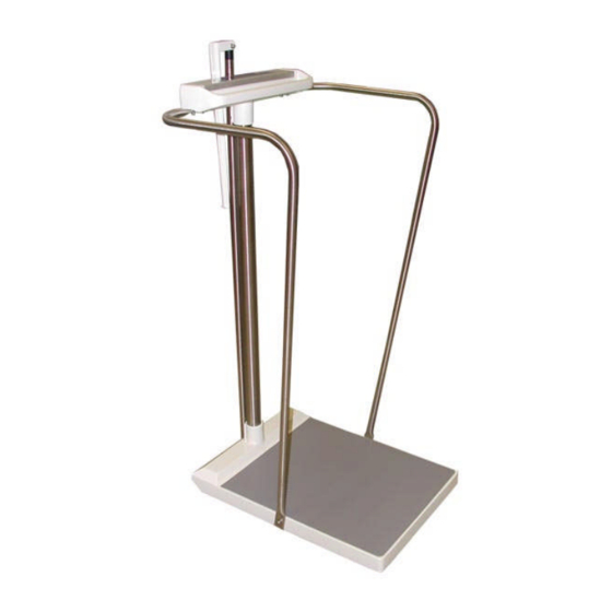
Model SR555 Stand-On Scale
Operating and Service Manual - S/N 1800+
Part No. MAN555_060829
Page 1 of 18
by S Instruments, Inc.
Stand-On Scale System
Operating and Service
Manual
Serial Numbers: 1800+
,
SInstruments, Inc.
600 Young Street, Tonawanda, NY 14150
Tel: 716-693-5977
Fax: 716-693-5854 URL:
www.srscales.com
Copyright 2006 SInstruments, Inc.
email:
sri@srinstruments.com
Advertisement
Table of Contents

Related Manuals for SR Instruments SRScales SR555


Summary of Contents for SR Instruments SRScales SR555
- Page 1 Model SR555 Stand-On Scale Operating and Service Manual - S/N 1800+ Part No. MAN555_060829 Page 1 of 18 by S Instruments, Inc. Stand-On Scale System Operating and Service Manual Serial Numbers: 1800+ SInstruments, Inc. 600 Young Street, Tonawanda, NY 14150 Tel: 716-693-5977 Fax: 716-693-5854 URL: www.srscales.com...
-
Page 2: Table Of Contents
Model SR555 Stand-On Scale Operating and Service Manual - S/N 1800+ Part No. MAN555_060829 Page 2 of 18 TABLE OF CONTENTS TABLE OF FIGURES........................2 PACKING CHECKLIST.........................3 ASSEMBLY............................4 REPLACEMENT PARTS AND ACCESSORIES ................6 SYSTEM DESCRIPTION AND INTENDED USE...............7 MAINTENANCE AND CLEANING....................7 STORAGE AND TRANSPORTATION ..................8 SPECIFICATIONS...........................9 BUTTON FUNCTIONS .........................10... -
Page 3: Packing Checklist
Model SR555 Stand-On Scale Operating and Service Manual - S/N 1800+ Part No. MAN555_060829 Page 3 of 18 PACKING CHECKLIST SR555 Stand-On Scale DESCRIPTION QUANTITY Box 1 BASE ASSEMBLY (FIVE (5) SET SCREWS IN PLACE) 1 ea MAST 1 ea DISPLAY UNIT WITH CABLE (FIVE (5) SET SCREWS IN PLACE) 1 ea PACKAGE OF SIX (6) “C”... -
Page 4: Assembly
Model SR555 Stand-On Scale Operating and Service Manual - S/N 1800+ Part No. MAN555_060829 Page 4 of 18 ASSEMBLY PART NAME Display Unit Base Assembly Mast Cable Clamp Display Cable Connector Handrails (optional) Height Bar (optional) Battery Compartment STEP 1: Unpack the scale system and check parts against the PACKING CHECKLIST. -
Page 5: Figure 2: Cable Clamp, Display Cable, Connector, And Set Screws
Model SR555 Stand-On Scale Operating and Service Manual - S/N 1800+ Part No. MAN555_060829 Page 5 of 18 ASSEMBLY cont’d STEP 6: (Figure 2) Lay the system on its side and remove the Cable Clamp (4) from the Base Assembly. Attach the Display Cable Connector (5) to its mate in the Base Assembly. -
Page 6: Replacement Parts And Accessories
Model SR555 Stand-On Scale Operating and Service Manual - S/N 1800+ Part No. MAN555_060829 Page 6 of 18 ASSEMBLY cont’d INSTALLING OPTIONAL HANDRAILS STEP 1: (Figure 4) Attach top of each of the Handrails (6) to the bottom right and left of the Display Unit (1) with the two (2) screws and two (2) split-lock washers on each side and slightly tighten. -
Page 7: System Description And Intended Use
Model SR555 Stand-On Scale Operating and Service Manual - S/N 1800+ Part No. MAN555_060829 Page 7 of 18 SYSTEM DESCRIPTION and INTENDED USE SYSTEM DESCRIPTION The SR555 Stand-On Scale System employs the latest in microprocessor and load cell technology to provide accurate and repeatable weight data. Four (4) identically matched transducers are strategically placed to ensure an accurate representation of the patient’s weight. -
Page 8: Storage And Transportation
Model SR555 Stand-On Scale Operating and Service Manual - S/N 1800+ Part No. MAN555_060829 Page 8 of 18 STORAGE and TRANSPORTATION STORAGE If storing this equipment for periods longer than three (3) months, remove the batteries. To maintain proper operation of this instrumentation, storage and transport conditions should not vary outside the following conditions: Relative Humidity 0% to 85%, Ambient Temperature 14F to 122F (-10C to +50C). -
Page 9: Specifications
Model SR555 Stand-On Scale Operating and Service Manual - S/N 1800+ Part No. MAN555_060829 Page 9 of 18 SPECIFICATIONS MAXIMUM WEIGHT CAPACITY 1000 lb or 454 kg 15 3/4 in x 18 1/2 in (40 cm x 47 cm) PLATFORM SIZE DISPLAY TYPE 16-Character Dot-Matrix LCD 0.1 lb/0.1 kg... -
Page 10: Button Functions
Model SR555 Stand-On Scale Operating and Service Manual - S/N 1800+ Part No. MAN555_060829 Page 10 of 18 BUTTON FUNCTIONS Press box under each icon to activate command Figure 5: Button Display ZERO The “ZERO” button is used to zero the system before placing a patient onto the scale system. -
Page 11: Battery Replacement
Model SR555 Stand-On Scale Operating and Service Manual - S/N 1800+ Part No. MAN555_060829 Page 11 of 18 BASIC SYSTEM OPERATION cont’d CONTINUOUS WEIGH In this default mode, the weighing surface remains active. Press the “HOLD” button once to lock the displayed reading and store it in memory as the “last weight”... -
Page 12: Theory Of Operation
Page 12 of 18 THEORY OF OPERATION SR Instruments patient weighing systems are digital scales. Strain-gauge force cells convert the force of an applied weight into an analog signal. This signal is amplified by an operational amplifier and converted to a digital signal by an analog to digital converter. The digital signal is transferred to a micro-controller where it is filtered, converted to appropriate units, and displayed on a liquid crystal display. -
Page 13: Calibration
Model SR555 Stand-On Scale Operating and Service Manual - S/N 1800+ Part No. MAN555_060829 Page 13 of 18 CALIBRATION IMPORTANT CALIBRATION CHECK Qualified service personnel only should perform this procedure. The SR555 load cell itself has no user serviceable components and should not be tampered with for any reason. -
Page 14: Initialization
Model SR555 Stand-On Scale Operating and Service Manual - S/N 1800+ Part No. MAN555_060829 Page 14 of 18 INITIALIZATION INITIALIZATION PROCEDURE To be used ONLY IF REPLACING IC5 or if DISPLAY READS DOUBLE Internal Initialization Buttons Figure 8: Location of Internal Initialization Buttons STEP 1: (Figure 8) Remove the two (2) screws on the bottom of the display housing. -
Page 15: Troubleshooting
Model SR555 Stand-On Scale Operating and Service Manual - S/N 1800+ Part No. MAN555_060829 Page 15 of 18 TROUBLESHOOTING SYMPTOM REASON/CORRECTIVE ACTION The characters only appear on half of the Press the “WEIGH” button or remove one battery. display. Wait five seconds, then re-install the battery and try the “WEIGH”... -
Page 16: Warranty
SR Instruments, Inc.’s part, and it neither assumes nor authorizes any other person to assume for SR Instruments, Inc. any other liabilities in connection with the sale of said articles. In no event shall SR Instruments, Inc. - Page 17 Model SR555 Stand-On Scale Operating and Service Manual - S/N 1800+ Part No. MAN555_060829 Page 17 of 18 NOTES SInstruments, Inc. 600 Young Street, Tonawanda, NY 14150 Tel: 716-693-5977 Fax: 716-693-5854 URL: www.srscales.com Copyright 2006 SInstruments, Inc. email: sri@srinstruments.com...
- Page 18 Model SR555 Stand-On Scale Operating and Service Manual - S/N 1800+ Part No. MAN555_060829 Page 18 of 18 By SInstruments, Inc. Precision & Technology in Perfect Balance SInstruments, Inc. 600 Young Street, Tonawanda, NY 14150 Tel: 716-693-5977 Fax: 716-693-5854 URL: www.srscales.com Copyright 2006 SInstruments, Inc.
Need help?
Do you have a question about the SRScales SR555 and is the answer not in the manual?
Questions and answers