
Related Manuals for Hellenbrand E3


Summary of Contents for Hellenbrand E3
- Page 1 Consumer’s Manual ©2014 Manufactured by: HELLENBRAND, INC. Phone: 608-849-3050 • Fax 608-849-7398 Web: www.hellenbrand.com • Email: info@hellenbrand.com...
-
Page 2: Table Of Contents
This owner’s manual is designed to assist owners with the operation and maintenance of your new water softener. It is our sincere hope that this manual is clear, concise and helpful. We have included information and instructions relating to the basics of soft water, general operating conditions, start-up, and meter &... -
Page 3: Soft Water Basics
1/2 full, salt bridging may occur in the brine tank. This may result in hard water due to ineffective regeneration. DO NOT USE Block Salt when the E3 control is programmed with a brine tank prefill. Block salt does not dissolve quickly enough to provide a good regeneration. -
Page 4: Frequently Asked Questions
FREQUENTLY ASKED QUESTIONS 1. Do I still use the same amount of soap in the dishwasher and clothes washer and showers now that I have a water softener? No, the Water Quality Association states soft water can save up to 55% on detergent use. Start with using half the amount of detergent previ- ously used, this can be adjusted up or down based on preference. -
Page 5: Programming Level 1
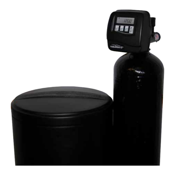
PROGRAMMING LEVEL 1 GENERAL INFORMATION The E3 control valve is the “brain” of your water softener. It consists of the valve body and powerhead with solid state microprocessor. The display panel (see Figure 2) consists of the LCD display and five push buttons which are used in displaying and programming the water softener settings. -
Page 6: Start-Up
START-UP BYPASS VALVE OPERATION Figure 3 Figure 4 Figure 5 Figure 6 INITIAL START-UP The initial start up will probably be done by the technician wash” appears. Slowly place the bypass valve into the installing the softener system. If not, the following instructions “Diagnostic Mode”... -
Page 7: General Operating Information
GENERAL OPERATING INFORMATION USER DISPLAYS/SETTINGS General Operation NORMAL OPERATION SCREENS REGEN TODAY When the system is operating, one of USER DISPLAY 1 DAYS TO A REGEN flashes in upper left REGEN TODAY CAPACITY REMAINING several displays may be shown. Pressing Typical user corner of display display. -
Page 8: Water Softener Disinfection
WATER SOFTENER DISINFECTION The construction materials of your water softener will not support under such trade names such as Clorox, Linco, Bo Peep, bacterial growth nor will these materials contaminate a water White Sail and Eagle Brand Bleach. If stronger solutions are supply. -
Page 9: Troubleshooting
B. Add salt to brine tank and maintain salt level above water level. 6. Unit uses too much salt. A. Improper brine refill setting. A. Contact your local Hellenbrand dealer for onsite service 7. Softener delivers salty water. A. Low water pressure. A. Run extra regeneration B. -
Page 10: Parts Diagrams
SERIES CONDITIONER & BRINE TANK ASSEMBLIES Item Description Part # Control Center-Metered 109370 Specify Size (see pages 13-17 for detailed components) Top Diffuser 101539 3&4 Mineral Tank Assembly Item 3 only Item 4 only Mineral Tank Distributor Assy -024 8 x 44 109290 101505 -032 9 x 48... - Page 11 GENERAL SPECIFICATIONS OPERATING PRESSURES Minimum/Maximum ..........................25 psi-120 psi OPERATING TEMPERATURES Minimum/Maximum ..........................40º - 110º F METER Accuracy ..............................±5% Flow Rate Range............................0.25 - 27 GPM Gallon Range ............................20 - 50,000 DIMENSIONS Drain Line ..............................3/4” or 1” NPT Brine Line ..............................3/8” Poly Tube Electrical Current Draw and Voltage ......................0.5A 110v Compatible with the following regenerants or chemicals: Sodium chloride, potassium permanganate, sodium bisulfite, sodium hydroxide, hydroxide, hydrochloric acid, chlorine and chloramines.
- Page 12 DRAWING IS THE SOLE PROPERTY OF HELLENBRAND INC. ANY REPRODUCTION IN PART OR AS A WHOLE WITHOUT THE DWG. NO. REV. WRITTEN PERMISSION OF HELLENBRAND INC. IS PROHIBITED. Figure 13 DRIVE CAP ASSEMBLY, DOWNFLOW PISTON, REGENERANT PISTON AND SPACER STACK ASSEMBLY QTY.
- Page 13 INJECTOR CAP, INJECTOR SCREEN, INJECTOR, PLUG AND O-RING QTY. ITEM NO. DESCRIPTION ORDER NO. 101375 Injector Cap 102159 O-ring 135 102457 Injector Screen 102319 Injector Assy. Z Plug-Filter 101825 Injector Assy. A Black 101826 Injector Assy. B Brown 101827 Injector Assy. C Violet 101828 Injector Assy.
- Page 14 DRAIN LINE - 3/4” ITEM NO. DESCRIPTION QTY. ORDER NO. 101414 Elbow Locking Clip 101871 Polytube Insert, 5/8” Optional 102131 Nut, 3/4” Drain Elbow Optional 101618 Drain Elbow 3/4” Male Assy-Vent Optional 101619 Drain Elbow 3/4” Male Assy-No Vent 102153 O-ring 019 102406 DLFC Retainer Assy.
-
Page 15: Bypass Valve
WATER METER AND METER PLUG ITEM NO. DESCRIPTION QTY. ORDER NO. 102141 Nut 1” QC 102051* Meter Assy. 102687 Turbine Assy. 102165 O-ring 215 102321 Meter Plug Assy.** *Order number 102051 includes 102687 and 102165, which are item numbers 3 & 4. **Only used if metering is not to be done (time clock units) The nuts and caps are designed to be unscrewed or tightened by hand or with the special plastic wrench. -
Page 16: Warranty
Water character- istics may change considerably if this System is moved to a new location. For these reasons, Hellenbrand assumes no liability for the determination of the proper equipment necessary to meet your needs;...
Need help?
Do you have a question about the E3 and is the answer not in the manual?
Questions and answers
What is "filter mode?"
What is filter mode?