Chapters
Table of Contents

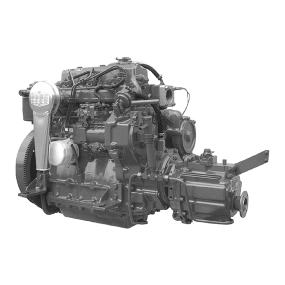
Related Manuals for Bukh DV36/48


Summary of Contents for Bukh DV36/48
- Page 1 Publ. No 009W2329 Aabenraavej 13-17, DK - 6340 Krusaa, Denmark Tel: +45 74 62 20 88 Fax +45 74 62 74 07 E-mail: bukh@bukh.dk – Internet: www.bukh.dk Work shop Manual BUKH diesel engine TYPE DV36/48 009W2329-R01...
- Page 2 Contents Section A … Introduction and technical data Section B … List of tools Section C … Cylinder head Section D … Flywheel Section E … Front end cover Section G … Rear end cover and hand start Section H … Fuel system Section IJ …...
- Page 3 SECTION A INTRODUCTION AND TECHNICAL DATA 009W2329...
-
Page 4: Table Of Contents
CONTENTS Introduction ................page A 3 Technical Data ................page A 4 Torques ..................page A 5 Spare Part Nos. for Service Parts ..........page A 6 Torque and Rating Curves ............page A 7 Results of Measurement ............page A 8 Longitudinal Section of DV36 ............ -
Page 5: Introduction
Introduction BUKH DV36 is a 3-cylinder, water cooled, 4-stroke diesel engine with direct injection, giving an easy start at low temperatures, a low consumption of fuel and a low thermic load of the cylinder head. The engines are specially designed to comply with the heavy demands made on stability, safety and environment now. - Page 6 TECHNICAL MAIN DATA WORKING PRINCIPLE……………………………………………………… ... 4-STROKE BORE/STROKE ..................85 mm / 85 mm CYLINDER VOLUME ................1.447 Litres COMPRESSION RATIO ................18,5:1 COMPRESSION PRESSURE …....at 1800-3600 rpm………… .. 46 Bar OUTPUT, CONTINOUS RATING.…..... at 2400 rpm………..……… .. 29.8 BHP - 21.9 kW ACCORDING TO ISO 3046…….
-
Page 7: Torques
BAYSAN M60 MARINEGEAR LUBRICATING OIL QUALITY ..............Automatic Transmission Fluid (ATF) LUBRICATING OIL TEMPERATURE............MAX. 120 LUBRICATING OIL CONTENT ..............0.5 Litres STERN TUBE (FLEXIBLE) LUBRICANT ........... OUTBOARD GEAR OIL COOLING WATER SYSTEM – DIRECT SEAWATER COOLING COOLING WATER TEMPERATURE ...... - Page 8 Spare Part Numbers for Service Parts In this manual we have maintained on the drawings some numbers which are also spare part numbers. However, this manual is not to be regarded as a spare parts catalogue but only as helping guidance for correct identification of parts. In the daily service work, some of the parts must be replaced after the number of hours stated in the owner´s manual and in this book, and therefore we have made the following table: 610J0200...
- Page 9 009W2329...
-
Page 10: Results Of Measurement
Results of Measurement The below curves indicate results of measurements at 762 mm Hg and a room temperature of 26 °C. 009W2329... -
Page 11: Longitudinal Section Of Dv36
Longitudinal Section of DV36 009W2329... -
Page 12: Cross Section Of Dv36
Cross Section of DV36 009W2329... -
Page 13: Diagram Of The Relation Between The Total Weight, Speed And Horse Power Of The Boat
Diagram of the Relation between the Total Weight, Speed and Horse Power of the boat The below diagram is normative and not binding in any way as many different circumstances influence the result, especially the type and shape of the boat, the propeller and its placing as well as the horse power of the engine. - Page 15 SECTION B LIST OF TOOLS 009W2329-R01...
- Page 16 CONTENTS Tools for repairs on DV36 ............page B 3 Dimensions of mounting punches ..........page B 6 009W2329-R01...
- Page 17 The below mentioned tools are necessary to make the engine repairs described in this manual. Part of the tools are special tools which can be ordered from the spare parts department at BUKH. We have indicated the fields of application for the special tools in this manual. Designation of tools Fields of application Spare part No.
- Page 18 Designation of tools Fields of application Spare part No. 36 mm socket spanner 19 mm socket spanner for Section C fastening of cylinder head 19 mm crowfoot wrench for Section C 009P3225 tightening up of cyl. head 10 mm Allen top for faste-ning of Section L bearing top section 5 mm Allen key...
- Page 19 Designation of tools Fields of application Spare part No. Flanging tools for nozzle holder Section C 009P2565 insert Torque wrench Generally 009P3108 (Stahlwille 73/6 1.5-6.5) Torque wrench Generally Section C, D, 009P3109 (Stahlwille 73/25 8-26) IJ and L Circlip tongs (external) A1, 10-28 mm Circlip tongs (internal) J2, 19-75 mm...
- Page 20 009W2329-R01...
-
Page 21: Cylinder Head
SECTION C CYLINDER HEAD 009W2329-R01... - Page 22 CONTENTS Exploded view of cylinder head complete ......... page C 3 Valve adjustment ..............page C 4 Removal and refitment of cylinder head ........page C 5 Replacement of rocker arm or rocker shaft ......page C 6 Adjustment of valve lifter arrangement ........page C 6 Replacement of rocker arm bushing .........
-
Page 23: Exploded View Of Cylinder Head Complete
Exploded view of cylinder head 009W2329-R01... -
Page 24: Valve Adjustment
Valve adjustment The clearance of the inlet and exha ust valves should be adjusted at 0.3 mm w hen the engine is cold and the clearance of the valves should always be checked after tightening- up of the c ylinder head. The valv es are adj usted when the pisto ns are alternately at their highest point in the working stroke. -
Page 25: Removal And Refitment Of Cylinder Head
Removal and refitment of cylinder head 1. Drain off the cooling water. 2. Remove the top cover. 3. Remove valve rocker arms. 4. Remove the inlet and return pipes of the fuel valves. 5. Remove the charging alternator. 6. Remove the exhaust and inlet manifold. 7. -
Page 26: Replacement Of Rocker Arm Or Rocker Shaft
Replacement of rocker arm or rocker shaft For each cylinder, a rocker arm column wit h two rocker arms for inlet valve and exhaust valve, respectively, is fitted on a common shaft with corresponding rocker arm columns and rocker arms for the two other cylinders. 1. -
Page 27: Replacement Of Rocker Arm Bushing
Replacement of rocker arm bushing 1. Remove the rocker arm as indicated on page C5 and check it as to wear and tear as well as fracture. 2. Press out the defective bushing with an adequate tool. 3. Fit the new bushing as shown below paying special attention to the position of the bearing joint and the oil grooves. -
Page 28: Removal Of Fuel Valves
Removal of fuel valves The fuel valves are removed by loosening the clamping nuts for the flanges A as indicated on the sketch below after removal of the inlet and return pipes of the fuel valves. The drawing at the bottom right-hand side indicates the placing of the fuel valve in proportion to the piston. -
Page 29: Nozzle Holder Insert
Nozzle holder insert The nozzle holder inserts are placed in the cylinder head and form – a the name indicates – an insert for the placing of the fuel valves in the cylinder head. The nozzle holder ins erts can be replace d, which demands that the sp ecial tools below for flanging (piston and backstop) are used and that t he surfaces are treated as indicated on the drawing. - Page 30 Fitting measurements for the fuel nozzle into insert. 009W2329-R01...
-
Page 31: Valve Springs
Valve springs Six identical springs for inlet and exhaust valves, respectively, are fitted in the cylinder head. The springs are identical in both ends, and therefore fitting up or down is of no importance. The springs are locked in their position in proportion to the valve stems by means of two conical halves for each valve spring and guided by a guide for valve spring and a corresponding disc, respectively. -
Page 32: Replacement Of Valve Guides
Replacement of valve guides Replace the valve guides whic h are pressed into the cylinder head if the tolerance is exceeded because of wear and tear by 0.05 mm. Check the measure with a ø9 – H7 internal gauge according to the drawing below of the valve guide. Fit new valve guides according t o the drawing on page C13. -
Page 33: Pressing-In Dimensions For Valve Guide
Pressing-in dimensions for valve guide. 009W2329-R01... -
Page 34: Valve Guide Stuffing Box
Valve guide stuffing box In order to avoid lubricating oil consumption because of lubricating oil passing between valve guide and valve stem causing the valves to be burnt or to be carbonized, a stuffing box has been mounted on the upper end of the valve guides. The stuffing box is as shown schematically on the drawing below and consists of: A: Metal spring coat B: Plastic bushing... -
Page 35: Repair Or Replacement Of Inlet And Exhaust Valves
Repair or replacement of inlet and exhaust valves Remove the cylinder head from the engine (page C5). Then place the cylinder head on a file bench or the like with the valve seats at the bottom. Compress the valve springs with a special tool or the like and remove the conical valve locking halves. -
Page 36: Exhaust Valve
Exhaust valve Tolerances and repair measures. 009W2329-R01... -
Page 37: Inlet Valve
Inlet valve Tolerances and repair measures. 009W2329-R01... -
Page 38: Grinding Of Valves
Grinding of valves 1. Place the cylinder head with the valve seats upwards. Block the cylinder head so that the valves fit tightly against the seats and can be turned freely by means of a rubber suction disc or the like. 2. -
Page 39: Replacement Of Valve Seats
Replacement of valve seats The valve seat rings should be replaced when, after repeated millings and grindings, they have been milled so far down that the valv e heads are more than 0.3 mm belo w the face of joint of the cylinder head (see the sketch below). 1. -
Page 40: Cylinder Head Gasket
Cylinder head gasket The cylinder head gasket is made from “Grafos eal” (Asbestos free) which is an expanded graphite which is strengthened with a special 0.2 mm carbon steel inlay. When replacing the cylinder head gasket, the grooves in the cylinder head must be completely clean to obtain tightness. -
Page 41: Air Inlet Manifold Arrangement
Air inlet manifold arrangement. Pos. Part No. Qty. Beskrivelse Description Benennung 000E4923 Indsugningsmanifold Inlet manifold Einlasssammelrohr 008E7310 Luftfilter Air filter Luftfilter 501A2363 12 Cylinderskrue Unbraco screw Unbracoschraube 522E0521 12 Låseskive Locking washer Arretierungsscheibe 009W2329-R01... -
Page 42: Exhaust Manifold Arrangement
Exhaust manifold arrangement. Pos. Part No. Qty. Beskrivelse Description Benennung 000E7434 Vandkølet udstødningsmanifold Water-cooled exhaust manifold Wassergekühltes Auspuffsammelrohr 000E5028 Pakning for udstødningsmanifold Gasket for exhaust manifold Dichtung für Auspuffsammelrohr 008E9239 Flange Flange Flansch 560F1031 O-ring O-ring Abdichtung 500C2363 Sætskrue M8x20 Set screw M8x20 Setzschraube M8x20 503N2367... - Page 43 SECTION D FLYWHEEL 009W2329-R01...
- Page 44 CONTENTS Removal and refitment of flywheel ..........page D 3 V-belt pulley fitted on flywheel ........... page D 3 Replacement of gear rim ............page D 4 009W2329-R01...
- Page 45 Removal and refitment of flywheel 1. Mark the flywheel in propor tion to the crankshaft out of consideration for the other marking of the outer diameter of the flywheel. 2. Slacken the V-belt for the charging alternat or and take it clear of the V-belt pulley of the flywheel.
- Page 46 Replacement of gear rim 1. Remove the flywheel. 2. Saw with a hacksaw as far int o the gear rim as possible without damaging the flywheel. 3. Split the gear rim in the sawed slot with a chisel. 4. Clean the recess on the flywheel. 5.
- Page 47 SECTION E FRONT END COVER 009W2329-R01...
- Page 48 CONTENTS Dismounting of front end cover ..........page E 3 Mounting of front end cover ............page E 3 Front rotating weight ..............page E 3 Replacement of front oil seal ring ..........page E 4 Replacement of bushes in the front rotating weight ....page E 4 009W2329-R01...
- Page 49 Dismounting of front end cover Dismount the flywheel (see page D3). Slacken the attachment of the end cover in engine block as well as in oil sump. Dismount the tightening arrangement for shaft for rotating weight. The tightening consists of two washers of different thickness and a fibre washer assembled by a 8 mm screw.
- Page 50 Replacement of front seal ring A seal ring is mounted in the front end cover in order to avoid lubricating oil waste at the end of the crank through the front end cover. The seal ring can be replaced without dismounting the front end cover. It is, however, necessary to dismount the flywheel.
- Page 51 SECTION G REAR END COVER AND HAND START 009W2329-R01...
- Page 52 CONTENTS Rear end cover ................page G 3 Dismounting of rear end cover ..........page G 3 Mounting of intermediate wheel and chain wheel ...... page G 4 Tightening for shaft for intermediate wheel ........ page G 4 Intermediate wheel ..............page G 5 Rear of rotating weight (drawing) ..........
-
Page 53: Rear End Cover
Rear end cover The rear end cover contains gear-wheel for crank, cam shaft, fuel pump,hand start, lubricating oil pump, cooling water pump and rear rotating weight. The gear-wheels are in the gear with each other through an intermediate wheel. The sketch below indicates the marking of the gear-wheels which have been marked in relation to each other so that their position to each other may easily be observed when being repared. -
Page 54: Mounting Of Intermediate Wheel And Chain Wheel
Mounting of intermediate wheel and chain wheel After the intermediate wheel has been placed on the shaft, and after the timing marks – as indicated overleaf – have been adapted for the corresponding marks, the chain wheel for hand start should be mounted on the same shaft. The two thrust collars shown form part of the arrangement. - Page 55 009W2329-R01...
- Page 56 009W2329-R01...
- Page 57 Mounting of the rear rotating weight Mount the rotating weight on the shaft pressed into the engine block and the tooth marking in relation to the intermediate wheel should be observed. After the end cover has been mounted, the tightening for shaft should be mounted in accordance with the drawing below.
-
Page 58: Intermediate Wheel
Replacement of bush in the rear rotating weight and intermediate wheel Bushes have been mounted in both rear rotating weights as well as in the intermediate wheel. These bushes can be replaced in case of wear and tear. After the new bushes have been pressed in these should be calibrated with a ball or be reamed with the correct measures and clearances as indicated on the drawings on page G5 and G6 for rear rotating weight and intermediate wheel respectively. -
Page 59: Chain Adjuster
Chain adjuster The chain adjuster is mounted on two pins in the engine block. The chain adjuster is self-adjusting and thus it does not require any adjustments in connection with repairs in the end cover during which the chain is to be dismounted. 009W2329-R01... -
Page 60: Hand Start
Hand start The chain case is bolted on to the rear end cover, as indicated on the drawing below. When dismounting remove the covers “A”, and this results in the chain being slackened and then the chain wheel and shaft can be taken out. Mounting is carried out in reverse order and it should be taken care that the O-rings for oil- tightness are correctly placed in the grooves on the chain wheel shaft. - Page 61 SECTION H FUEL SYSTEM 009W2329.XLS...
- Page 62 CONTENTS: Dismounting of the fuel pump ............page H 3 Mounting and Adjustment for fuel pump ......... page H 4 Specification of Numbers to Fig. 1 and 2 ........page H 6 Fuel System ................... page H 7 Centrifugal Governor ..............page H 8 Function of the Centrifugal Governor ..........
-
Page 63: Dismounting Of The Fuel Pump
Dismounting of the fuel pump 1. Dismount the bilge pump for lubricating oil from engine and gear. 2. Dismount the flange opposite of the fuel pump. 3. Take off the gear-wheel of the pump by slackening the clamping nut on the shaft of the pump and pull off the gear-wheel. - Page 64 1. Turn piston No. 3 (rear) to TOP in the working stroke. 2. Mark the flywheel in this position in relation to the arrow mounted on the front edge of the engine. 3. Measure 86 mm. arc measure from the TOP mark (to the right, when the flywheel faces you).
- Page 65 4. The pump should be adjusted for correct injection timing: a. Adjust the key on the conical shaft of the pump so that it flushes with the outlet hole B to the fuel valve for cylinder No. 3. b. Remove the screw X and mount a dial indicator with a special sensing element instead by means of a special holder for dial indicator.
-
Page 66: Specification Of Numbers To Fig. 1 And 2
Specification of Numbers to Fig. 1 and 2 1. Feed pump 2. Drive shaft 3. Gear-wheel 4. Thrust washer 5. Governor shaft 6. Governor bush 7. Holder 8. Governor weight 9. Governor spring 10. Timing lever 11. Adjusting screw (idling) 12. -
Page 67: Fuel System
Fuel System The fuel is pumped by a lift pump (29 from the tank via a fine filter (30) to the internal wing feed pump. This feed pump gives a constant quantity/revolution. Through the pressure control valve (31), after the feed pump, a pressure is produced. Most of the fuel flows through the pressure control valve back to the suction side. - Page 68 The centrifugal governor is placed in the upper part of the fuel pump. The holder (7) with gear-wheel is placed on the governor shaft (5) and is driven by the drive shaft (2) via the gear-wheel (3) and a rubber shock absorber (vibration damper). Four weights (8) are mounted in the centrifugal weight holder.
-
Page 69: Function Of The Centrifugal Governor
Function of the Centrifugal Governor The revolutions of the engine are transmitted by the drive shaft (2) through gear-wheel to the governor weights (8) and are transformed into centrifugal force there. With stopped fuel pump, the starting lever (21) and the governor slide (24) are pressed into start position by the starter spring (20). -
Page 70: Fuel Lift Pump
Fuel Lift Pump The fuel lift pump is a diaphragm type and is placed at the upper side of the rear end cover. The pump is sealed and cannot be dismantled for repair or cleaning. It is driven by the camshaft. -
Page 71: Fuel Filter
Fuel Filter The fuel filter used is a Bosch disposable one mounted to the port side on the front of the engine. The filter cannot be cleaned, but has to be changed every 300 operating hours, or if water contamination is suspected. Unscrew the filter casing by hand after the filter casing has been emtied for fuel via the drain screw in the bottom of the filter casing. - Page 72 The fuel valves are mounted in the cylinder head and are secured here with tightening bars which are loosened when dismounting the fuel valves. Disassemble the fuel valves after the sketch beside and so the nozzle can be exchanged and the pressure can be adjusted at the washers (541).
-
Page 73: Causes And Remedies Of The Fuel Pump
Causes and Remedies of the Fuel Pump 009W2329.XLS... - Page 75 SECTION IJ PISTON, CONNECTING ROD AND CYLINDER LINER 009W2329-R01...
- Page 76 CONTENTS Disassembling of pistons and connecting rods ......page IJ 3 Assembling of pistons and connecting rods ......page IJ 3 Exchange of pistons ..............page IJ 4 Measurement of piston .............. page IJ 5-6 Piston rings ................page IJ 7-8 Exchange of piston rings ............
-
Page 77: Disassembling Of Pistons And Connecting Rods
Disassembling of Pistons and Connecting Rods 1. Drain off the cooling water and the lubricating oil from the engine. 2. Dismount the cylinder head (see section C). 3. Remove any wear or soot edge which may be at the top of the cylinder liner with a scraper. 4. -
Page 78: Exchange Of Pistons
Exchange of Pistons If the pistons are scored or very worn, exchange them for new ones. This is carried out as follows: 1. Remove the pistons with connecting rods as stated on page IJ 3. 2. Take off one of the locking rings at the gudgeon pin. 3. - Page 79 Measurements for Piston 009W2329-R01...
- Page 80 009W2329-R01...
-
Page 81: Piston Rings
Piston Ring 1 (Please note page IJ4) 009W2329-R01... - Page 82 Piston Ring 3 ( Please note page IJ4) 009W2329-R01...
-
Page 83: Exchange Of Piston Rings
Exchange of Piston Rings The piston ring gap is 0.3 – 0.45 mm (0.0118 - 0.0177 inch) in a new engine. The wear of the piston rings ca n be seen by measuring the piston ring gap, and the piston rings must be changed when this is max. -
Page 84: Arrangement Of Connecting Rod (Drawing)
IJ10 Arrangement of Connecting Rod 009W2329-R01... -
Page 85: Connecting Rod Bearings
IJ11 Connecting Rod Bearings The connecting rod bearings are in two parts and consists of two steel shells in which a thin layer of bearing metal is cast. The connecting rod bearings must be exchanged if they are scratched or if the “red” layer between the bearing metal and the steel shell can be seen faintly. -
Page 86: Cylinder Liner
IJ12 Cylinder liner The bore of the cylinder liner is 85.000 – 85.020 mm (3.3464 – 3.3472 inch). The cylinder liner must be exchanged when it is worn max. 0.3 mm (0.012 inch). Measuring of Cylinder Wear Place a new piston ring in the upper end of the liner where this is not worn. Measure the piston ring gap with a feeler gauge. - Page 87 IJ13 Test Measurements of Cylinder Liner 009W2329-R01...
- Page 89 SECTION L CRANKCASE, CRANKSHAFT, MAIN BEARINGS AND OIL SUMP 009W2329-R01...
- Page 90 CONTENTS Dismounting of crankshaft ............page L 3 Change of main bearings ............page L 3 Rear part of crank ..............page L 4 Rear gear-wheel and rear part of crank ........page L 5 Marking of front gear-wheel on crank ........page L 6 Front part of crank ..............
-
Page 91: Dismounting Of Crankshaft
Dismounting of crankshaft 1. Remove the cylinder head with manifold (see section C page 4). 2. Dismount the flywheel (see section D page 3). 3. Dismount the gear (see section R page 3). 4. Dismount the rear end cover (see section G page 3). 5. -
Page 92: Rear Part Of Crank
Rear part of crank The drawing below shows the rear part of the crank with screwing-on of the counter weights of the crankshaft. Drwg. No. 008E4757 009W2329-R01... -
Page 93: Rear Gear-Wheel And Rear Part Of Crank
Rear gear-wheel and rear part of crank 009W2329-R01... -
Page 94: Marking Of Front Gear-Wheel On Crank
Marking of front gear-wheel on crank The front gear-wheel on the crank drives the front rotating weight and is marked in proportion to this and in accordance with the drawing below. The gear-wheel has been shrinked on the shaft. When shrinking on a new gear-wheel there should be a difference of temperature between the crankshaft and the gear-wheel of 231 C. -
Page 95: Front Part Of Crank
Front part of crank 009W2329-R01... -
Page 96: Repair Dimensions Of Crakshaft
Repair dimensions of crankshaft The crankshaft is made of drop-forged, heat-treated steel. Thus it is possible to gring the crankshaft without subsequent surface treatment. The crankshaft must never be repaired with hard chromium-plate or metal feeding, but only by grinding in accordance with the below mentioned measures and tolerances to which we supply undersize bearings. -
Page 97: Oil Sump
Oil Sump The engine is fitted with an oil sump of cast iron. The oil sump is fixed to the crankcase and is ensured correct position to this by means of guide pins. Under the oil sump the suction strainer for the lubricating oil system is placed and pipe connections for it. - Page 99 SECTION M CAMSHAFT, COMPLETE 009W2329-R01...
- Page 100 CONTENTS Camshaft ................... page M 3 Valve timings ................page M 4 Guide for push rod ..............page M 4 Gear-wheel of camshaft ............page M 5 Drawing of push rod ..............page M 6 Drawing of push rod guide ............page M 7 009W2329-R01...
-
Page 101: Camshaft
Camshaft The camshaft runs in borings in the engine block, and it has been forced-lubricated through grooves bored in the engine block. A bush for the camshaft is fitted in the front end of the engine block. There is a hole for lubricating oil inlets in this bush. -
Page 102: Valve Timings
Valve timings and injection point Flywheel diameter ........... 370 mm Inlet valve opens ......before TDC: 32° (arc measure: 103 mm (4.07”)) Inlet valve closes ......after BDC: 64° (arc measure: 207 mm (8.14”)) Exhaust valve opens ....before BDC: 64° (arc measure: 207 mm (8.14”)) Exhaust valve closes .... -
Page 103: Gear-Wheel Of Camshaft
Gear-wheeI of camshaft The camshaft gear-wheel is equipped with a single mark for its correct position in relation to the rear rotating weight and a double mark in relation to intermediate wheel (see instructions in section G page 3). 009W2329-R01... -
Page 104: Drawing Of Pushrod
Drawing of pushrod Drwg. No. 000E9455 009W2329-R01... -
Page 105: Drawing Of Push Rod Guide
Drawing of push rod guide 009W2329-R01... - Page 107 SECTION N LUBRICATING OIL SYSTEM 009W2329-R01...
- Page 108 CONTENTS Lubricating oil system ..............page N 3 Pressure relief valve ..............page N 3 Fitting of dip stick ............... page N 4 Pipe connections in oil sump ............. page N 5 Lubricating oil pump ..............page N 6 Removal of lubricating oil pump ..........page N 6 Lubricating oil cooler ..............
-
Page 109: Lubricating Oil System
Lubricating oil system The engine is lubricated through a pressure l ubrication system. The lubricating pump driven by the camshaft sucks oil from the oil sump th rough a strainer. From the lubricating pump the oil is pressed through a fine filter to the respective lubr icating points through oil ducts bored in the goods. -
Page 110: Fitting Of Dip Stick
Fitting of dip stick 009W2329-R01... -
Page 111: Pipe Connections In Oil Sump
Pipe connections in oil sump 009W2329-R01... -
Page 112: Lubricating Oil Pump
Lubricating oil pump The lubricating oil pump is placed below the rear end cover and actuated via the rear gear-wheel of the crank and a gear-wheel fixed to the shaft of the pump. The pump is an Eaton pump with star rotor and life ring. When the engine runs at full speed, the pump runs 4000 r.p.m. -
Page 113: Lubricating Oil Cooler
Lubricating oil cooler The standard engine is equipped with a lubricating oil cooler, fitted as shown on the drawing below. On the water side the cooler is connected between the cooling water pump and the cooling water suction hose, and on the oil side it is connected to the outlet of the lubricating oil pump to the lubricating oil system. -
Page 114: Change And Quality Of Lubricating Oil
Change and quality of lubricating oil Exchange the lub. oil every 150 operating hours or once a year. This is done with a bilge pump, fitted on the engine. This pump can be set for emptying the engine or gearbox of lub. oil by means of the three-way cock. Lub. -
Page 115: Lubricating Oil Filter
Various makes of oil filters can be used as e.g. the motor-car industry uses the filter type used, as standard. The BUKH filter used is of make Mann & Hummel type W9.30. 009W2329-R01... - Page 117 SECTION O COOLING WATER SYSTEM 009W2329-R01...
- Page 118 CONTENTS Cooling water systems .............. page O 3 Johnson cooling-water pump type F5B9 ........page O 4 Removal of pump ..............page O 4 Dismantling of pump ..............page O 4 Dismantling of intermediate housing ......... page O 4 Reassembly of pump ..............page O 5 Refitment of pump ..............
- Page 119 The engine can be c ooled by direct seawater cooling which is supplied as standard cooling system. Alternatively freshwater cooling can be supplied as extra equipment and this c an be arranged in three different ways: either with heat exchanger, keel cooler or with radiator cooling.
-
Page 120: Johnson Cooling-Water Pump Type F5B9
Johnson cooling water pump type F5B9 The cooling water pump is used for direct s eawater cooling with a cam heigh t 0f 2.0 mm and for freshwater cooling with heat exchanger to the seawater si de with a cam height of 3.1 mm (see technical data page A5). -
Page 121: Reassembly Of Pump
Reassembly of pump The pump should be assembled in the reverse order of the dismantling. Observe that the ball bearings of the intermediate housing are filled with grease free from acid. Refitment of the pump Fit the pump in the reverse order of the removal and check that the rubber gasket ring marked H fits tightly. - Page 122 Johnson cooling water pump: After DV36 serial No. 1051 the outer dimensi ons of the Johnson cooling water pump have been changed and the pump has been par tly simplified at the same ti me, as e.g. the carbon ring stuffing box has been left out. The type and the technical data of the pum p and height of the cam in ca se of direct seawater cooling and indirect freshwater cooling respectively are the same for the new pump as for the one previously used.
- Page 123 Removal of the pump 4. Loosen the three screws in the flange marked 20. 5. Remove the cooling water pipes going to and from the pump. 6. Lift the pump free in one piece from its attachment in the engine block. Dismantling of the pump 5.
-
Page 124: Circulation Pump For Freshwater
Circulation pump for freshwater The circulation pump shown on page O7 is used for freshwater cooling, both when cooled by heat exchanger and by keel cooling. Removal of circulation pump 1. Remove the inlet and outlet pipes from the pump. 2. -
Page 125: Circulation Pump
Circulation pump 009W2329-R01... -
Page 126: Zinc Rod Protection
Zinc rod protection For seawater-cooled engines it is necessary to fit zinc anodes in the cooling water system in order to protect against corrosion of the engine block. On the starboard side of the engine under the exhaust manifold there therefore are three mounting holes for zinc anodes. -
Page 127: Thermostate
Thermostate For controlling the cooling water temperature the cooling water system is fitted with a thermostate. Dependent on the cooling principle the thermostate has different opening temperatures. In case of direct seawater cooling the thermostate has an opening temperature of 50°C. In case of freshwater cooling the thermostate has an opening temperature of 80°C. -
Page 128: Header Tank And Heat Exchanger
Header tank and heat exchanger The arrangement of header tank and heat exchanger fitted on the top of the water cooled exhaust manifold is shown on page O11. In case of keel cooling the arrangement only serves as header tank and from the factory it has been prepared for this by changes in proportion to the use as heat exchanger/ header tank, and directly it will not be possible to change the function from keel cooling into heat exchanger cooling without buying a new header tank or heat exchanger/header tank prepared for the... - Page 129 009W2329-R01...
- Page 130 009W2329-R01...
- Page 131 SECTION P ELECTRICAL SYSTEM 009W2329-R01...
- Page 132 CONTENTS Wiring diagram (key switch) ............page P 3 Wiring diagram (key switch) – 2 battery starting system.... page P 4 Wiring diagram (push button) ............ page P 5 Wiring diagram (push button) – 2 battery starting system ..page P 6 Generator with double charging diodes ........
- Page 133 009W2329-R01...
- Page 134 009W2329-R01...
- Page 135 009W2329-R01...
- Page 136 009W2329-R01...
- Page 137 Generator with double charging diodes Drg.no. 009V0053 009W2329-R01...
- Page 138 009W2329-R01...
- Page 139 009W2329-R01...
- Page 140 009W2329-R01...
- Page 141 SECTION R ZF GEAR – BW7 009W2329-R01...
- Page 142 CONTENTS Gear ratio .................. page R 3 Oil change ................. page R 3 Special tools ................page R 5 Adjusting measures and torques for BW7 ......... page R 6 General information for work with the gear ........ page R 8 Removal of gear from engine ............
-
Page 143: Gear Ratio
Gear Ratio The BW7 gear which is used on DV36 has normally a reduction ratio of 3.0:1 for AHEAD and 2.36:1 for REVERSE. For special purposes it can be delivered with a reduction ratio of 2.47:1 for AHEAD and 2.36:1 for REVERSE. Oil Change The gear will need no other attendance than regular change of oil. - Page 144 009W2229...
-
Page 145: Special Tools
Special Tools Order No. 009P3187 Mounting punch for seal ring 25x33x6 at input shaft Order No. 009P3188 Internal puller for tapered roller bearings / outer ring Order No. 009P3189 For fitting of tapered roller bearings / outer ring in connection with 009P3188 Order No. -
Page 146: Adjusting Measures And Torques For Bw7
Adjusting Measures and Torques for BW7 Designition Statement of Gauge Remarks dimensions Axial tightening of tapered 0.03 – 0.08 mm Dial indicator Adjusted by means of washer (s) roller bearings on input With a load of under bearing outer ring in the and output shafts 30 N (3 Kp) Depth... - Page 147 Adjusting Measures and Torques for BW7 Designition Statement of Gauge Remarks dimensions Testing indication for L = 11.4 mm Depth L = length of loaded spring pressure spring 0732 041 P = 46±5 N measure 008 for shift pins (4.6±0.5 Kp) P = spring power Weight Torque of hexagon nut...
-
Page 148: General Information For Work With The Gear
General Information for Work with the Gear Show cleanliness when repairing the gear and before the gear is opened it must be carefully cleaned. Use special tools as stated earlier in this section when removing and fitting the gear. The seal face between the two parts of the housing is tightened with liquid jointing. When dismantling the halves of the gearbox from each other, loosen the screws in the flanged joint first and push/press back the fitting pins. -
Page 149: Dismantling Of Bw7 Gear
Dismantling of BW7 Gear Pull the dip stick of the housing. Remove the locking ring on the input shaft. Remove the shifting arrangement with gasket. There are two different shifting levers which, however, can be built in without any problems in either cases. - Page 150 Unscrew the nut of the output shaft flange. Pull off the output shaft flange. Screw off the fixing screws which hold the halves of the gearbox together. 009W2229...
-
Page 151: Removal Of Input And Output Shafts
Drive back the fitting pins 2 – 3 mm in the gearbox and lift one gearbox half with reversing shaft, input and output shafts free of the other gearbox half. Protective sleeve 1 x 56 136 992 may be fitted on the input shaft before the dismantling. Removal of Input and Output Shaft ProTake out the screws M8x25 and the gear- wheel bolts and remove the washer plate. -
Page 152: Dismantling Of Shifting Fork
Dismantling of Shifting Fork Screw out the pin M6x12 of the shifting fork and press out the reversing shaft of the shifting fork. At the fitting the threaded pin has been smeared with Loctite No. 241 and so it may be necessary to heat. - Page 153 Remove the thrust collar wuth bolts and washers together wuth needle bearing bushing, sliding sleeve and pressure spring. Remove the wheel “AHEAD” with a special tool and take off all parts “AHEAD”. 009W2329-R01...
-
Page 154: Dismantling Of Input Shaft
Dismantling of Input Shaft Squeeze off the tapered roller bearing inner collar. Dismantling of Lower Gearbox Half Pull out the tapered roller bearing outer collars of the lower gearbox with an inner puller No. 1 x 56 122 208 and auxiliary tool No. -
Page 155: Refitment Of Bw7 Gear
Refitment of BW7 Gear Before refitment of the gear examine the different components for cracks and wear. In the following description only the fitting of output shaft for “AHEAD” is described as the fitting for “ASTERN” is chiefly corresponding. If it is necessary reference will be made to the paragraph marked “Note”. - Page 156 Fit the tension rollers on the shafts for suspension by rollers. “Note”: The tension rollers must be placed so that the big surface lies outwards. Fit the pressure springs in the check bolts. Fit the check bolts in the corresponding bores.
- Page 157 Fit needle bearing housing, wheel for “AHEAD” and washer. Check the axial clearance of wheel for “AHEAD”. It should be 0.1 – 0.4 mm. “Note”: For “ASTERN” the axial clearance can be adjusted by fitting an intermediate washer (thrust washer). First fit a washer.
- Page 158 Fit thrust washer, the oil pockets of which should turn towards the wheel for “AHEAD”. Fit the disc springs which should touch with the outside diameter. Check the tightening of the disc springs. The inside diameter of the disc springs must, when slack, in proportion to the front be min.
- Page 159 Heat the tapered roller bearing inner collar to about 85°C and fit it with the thin end of the taper roller facing the shaft end of the output shaft until it fits tightly against the disc springs. Tighten the tapered roller bearing with bush No.
-
Page 160: Fitting Of Input Shaft
The picture shows the ready-mounted output shaft. Fitting of Input Shaft Heat the tapered roller bearing inner collars to about 85°C and fit it with the thin end of the bearings towards the shaft ends. “NOTE”: Fit wide tapered roller bearing on the input side. - Page 161 Measuring of Tightening of Tapered Roller Bearing on Input and Output Shafts with Measuring Gauge. 1 = Housing 3 = Depth micrometer 5 = Output shaft 2 = Input shaft 4 = Measuring gauge 1 x 56 136 978 Heat the bearing bores in the housing to about 85°C and fit the tapered bearing outer collars with Loctite No.
- Page 162 1 = Bearing bushing 2 = Measuring gauge 3 = Depth micrometer Fit the measuring gauge on lower gearbox half. Calculate the thickness of the intermediate washer G as follows: Establish measure E as D minus B (thickness of measuring gauge). Calculate the difference measure F as E minus A (See picture No.
- Page 163 Measuring of Tapered Roller Bearing tightening on Input and Output Shafts without Measuring Gauge. 1 = Dial indicator holder 2 = Input shaft 3 = Dial indicator 4 = Driving arrangement It would be an advantage, if the input shaft and the output shaft are measured individually for the adjusting of the tapered roll er bearing tightening.
-
Page 164: Premounting Of Shifting Fork
Picture No. 37 continued Measuring example: Thickness of intermediate washer during the measuring procedure: 0.60 mm Measured axial clearance of shaft: 0.08 mm Correct tightening 0.03 – 0.08 mm (average value): 0.055 mm Thickness of compressed liquid jointing: 0.02 mm Theoretical thickness of intermediate washer: 0.755 mm In practice the intermediate washer will be 0.73 –... - Page 165 1 = Shifter shaft 2 = Shift pin 3 = Pressure spring 4 = Gearbox 5 = O-ring 6 = Shift control lever 7 = Grease lubrication 8 = Screw cap Insert pressure spring, shift pin, oiled shifter shaft and O-ring in the gearbox. Press the shift control lever on to theshifter shaft so tha t shift control leveris placed in neutral position at...
-
Page 166: Fitting Of Bolts In Gearbox
Fitting of Bolts in Gearbox Drive in t he slotted pins 4x16 in thebolts and fit the washers on the bolts so that the lubricating groove in them point to the wheel. “NOTE”: The bolt must be fitted in pos. 1 or 2 all depending on the transmission. -
Page 167: Fitting Of Input And Output Shafts With Shifting Fork In Gearbox
Fitting of Input and Output Shafts with Shifting Fork in Gearbox Place the shaft arrangement as shown on the picture. “NOTE”: The long side of the reversing shaft faces the input side. Fit the intermediate wheel and needle bearing. Lift intermediate wheel with s plate (see illustration). - Page 168 Place the housing so that the opening of it turns upwards. Oil the roller bearings and reversing shaft and fit them together in the housing. Remove the stop plate. “NOTE”: The long side of the reversing shaft points upwards to the input side.
- Page 169 Smear the seal f aces of the gearbox halves wit h permanently plastic liquid jointing. Oil the bearings on the input and output shafts. Assemble the gearbox and drive in the guide pins. Tighten the screws M8x25 with a torque of 17 Nm (1.7 Kpm). 009W2329-R01...
-
Page 170: Fitting Of Shaft Seal Rings
Fitting of Shaft Seal Rings Fit the protective cap No. 1 x 56 136 992 over the input shaft. Smear the seal ring 25 x 33 x 6 with a thin layer of grease on the lip ring and smear with a thin lay er of plastic liquid jointing on the outside. -
Page 171: Supplement To Fitting Of Shaft Seal Rings
Supplement to Fitting of Shaft Seal Rings A = Distance to shaft seal ring: 22.5 ±0.5 mm. B = Shaft seal ring binding with surface of casting on the lower gearbox half. The picture shows the necessary mounting dimensions for the shaft seal rings on the input and output shafts. - Page 172 Heat the output flange to about 85°C and fit it on the output shaft. Smear the nut with permanently plastic liquid jointing and secure it with a torque of 100 Nm ( 10 Kpm). 009W2229...
- Page 173 Picture 55 Fit the screws M8x25 with washers in the gearbox. Put the gear shift lever in “neutral” (the sliding sleev e is also in “neutral” position). Place the gearbox with gask et in the opening of the housing and pr ess the shifting eccentric down into the shifting fork.
- Page 175 SECTION S SAIL DRIVE TYPE Z-7 009W2329-R01...
- Page 176 CONTENTS Oil change and gear ratio ............page S 3 Zinc anode ................. page S 3 Outside maintenance ..............page S 3 Removal of sail drive from engine and boat ......page S 3 Alarm function of double membrane .......... page S 5 General (for assembly and dismantling of sail drive) ....
-
Page 177: Oil Change And Gear Ratio
Do not grind thoroughly when careening the boat. Damage to the surface treatment should be treated as soon as possible with special BUKH paint. The sail drive should be coated with the same bottom paint as the rest of the bottom of the boat. - Page 178 009W2329-R01...
-
Page 179: Alarm Function Of Double Membrane
‘ Alarm Function of Double Membrane A sensing element is fitted in the double membrane. The element is shown on the diagram below. The sensing element is connected to the the operating panel and if water penetrates into the double membrane it will release an acoustic alarm. As a precaution the alarm function should be checked once or twice a year by short-circuiting the connections 1 and 2 on the plastic box No. -
Page 180: General (For Assembly And Dismantling Of Sail Drive)
The special tools mentioned in this instruction are not numbered, but can be ordered with reference to this section of the workshop manual through BUKH´s spare parts department. Both distance measure and flange clearance are always marked on the wheels, and they apply to the wheel on which they are written. -
Page 181: Assembling Procedure For Sail Drive
Assembling Procedure for Sail Drive Measure the intermediate piece (between engine and clutch housing), the clutch housing and the end cover for the same, and then the “K” measure can be worked out. Up-end the clutch shaft so that any clearance is equalized. (about 2 kg compression, if it is not possible to up-end the shaft). - Page 182 Measure on the intermediate wheel as follows: 1.0 mm is chosen as thickness of the intermediate washer “III” as starting point. Freeze the gear-wheel and measure the stagger between the inner collar and outer collar of the bearing. Fit the bearing with the ball filler hole facing the adjusting washer “IV”. Fit the next bearing correspondingly.
- Page 183 21. Calculate the “T” measure. The “S” measure is stamped on the gear-wheel whereas the “R” measure has to measure. “T” measure = “S” measure minus “R” measure. 22. The intermediate washer ”VIII ” should be: the sum of “T” measure and “Q” measure minus the difference of “U”...
- Page 184 009W2329-R01...
- Page 185 009W2329-R01...
- Page 186 009W2329-R01...
- Page 187 009W2329-R01...
- Page 189 SECTION T IRREGULAR OPERATION, CAUSES AND REMEDIES 009W2329.R01...
- Page 190 CONTENTS Engine does not start ..............page T 3 The engine starts, but stops soon after ........page T 3 The engine does not reach maximum output ......page T 3 Knocking operation of engine ............ page T 3 Engine speed too high ............... page T 3 The engine knocks ..............
- Page 191 1. Engine does not start SYMPTOM CAUSE REMEDY Insufficient or very little compression Inlet and/or exhaust valves leaking Grind or replace the valves, mill the seats Grease valve stems with 2/3 gas oil and 1/3 lub. Inlet and/or exhaust valves sticking Oil.
- Page 193 SECTION V MAINTENANCE 009W2329-R01...
- Page 194 CONTENTS Recommended maintenance and check list ......page V 3 009W2329-R01...
- Page 195 RECOMMENDED MAINTENANCE AND A CHECK LIST FOR BUKH ENGINES EVERY CHECK RECTIFY IF NEEDED YEARS Tightness of connections through hull: stern tube hull connection change sealing Check of lubricating oil: 2.1 a engine change oil 2.1.b engine check oil level 2.2.a gearbox...
Need help?
Do you have a question about the DV36/48 and is the answer not in the manual?
Questions and answers