
Related Manuals for Bukh DV10


Summary of Contents for Bukh DV10
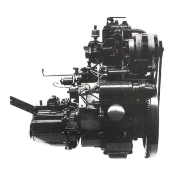
- Page 1 Publ. No 009W2228 Aabenraavej 13-17, DK - 6340 Krusaa, Denmark Tel: +45 74 62 20 88 Fax +45 74 62 74 07 E-mail: bukh@bukh.dk – Internet: www.bukh.dk Work shop Manual BUKH diesel engine TYPE DV10/20 009W2228...
- Page 245 SECTION R ZF GEAR – BW7 009W2229-R01...
-
Page 246: Table Of Contents
CONTENTS Gear ratio .................. page R 3 Oil change ................. page R 3 Special tools ................page R 5 Adjusting measures and torques for BW7 ......... page R 6 General information for work with the gear ........ page R 8 Removal of gear from engine ............ -
Page 247: Gear Ratio
Gear Ratio The BW7 gear which is used on DV24 has normally a reduction ratio of 3.0:1 for AHEAD and 2.36:1 for REVERSE. For special purposes it can be delivered with a reduction ratio of 2.47:1 for AHEAD and 2.36:1 for REVERSE. Oil Change The gear will need no other attendance than regular change of oil. - Page 248 009W2229-R01...
-
Page 249: Special Tools
Special Tools Order No. 009P3187 Mounting punch for seal ring 25x33x6 at input shaft Order No. 009P3188 Internal puller for tapered roller bearings / outer ring Order No. 009P3189 For fitting of tapered roller bearings / outer ring in connection with 009P3188 Order No. -
Page 250: Adjusting Measures And Torques For Bw7
Adjusting Measures and Torques for BW7 Designition Statement of Gauge Remarks dimensions Axial tightening of tapered 0.03 – 0.08 mm Dial indicator Adjusted by means of washer (s) roller bearings on input With a load of under bearing outer ring in the and output shafts 30 N (3 Kp) Depth... - Page 251 Adjusting Measures and Torques for BW7 Designition Statement of Gauge Remarks dimensions Testing indication for L = 11.4 mm Depth L = length of loaded spring pressure spring 0732 041 P = 46±5 N measure 008 for shift pins (4.6±0.5 Kp) P = spring power Weight Torque of hexagon nut...
-
Page 252: General Information For Work With The Gear
General Information for Work with the Gear Show cleanliness when repairing the gear and before the gear is opened it must be carefully cleaned. Use special tools as stated earlier in this section when removing and fitting the gear. The seal face between the two parts of the housing is tightened with liquid jointing. When dismantling the halves of the gearbox from each other, loosen the screws in the flanged joint first and push/press back the fitting pins. -
Page 253: Dismantling Of Bw7 Gear
Dismantling of BW7 Gear Pull the dip stick of the housing. Remove the locking ring on the input shaft. Remove the shifting arrangement with gasket. There are two different shifting levers which, however, can be built in without any problems in either cases. - Page 254 Unscrew the nut of the output shaft flange. Pull off the output shaft flange. Screw off the fixing screws which hold the halves of the gearbox together. 009W2229-R01...
-
Page 255: Removal Of Input And Output Shafts
Drive back the fitting pins 2 – 3 mm in the gearbox and lift one gearbox half with reversing shaft, input and output shafts free of the other gearbox half. Protective sleeve 1 x 56 136 992 may be fitted on the input shaft before the dismantling. Removal of Input and Output Shaft ProTake out the screws M8x25 and the gear- wheel bolts and remove the washer plate. -
Page 256: Dismantling Of Shifting Fork
Dismantling of Shifting Fork Screw out the pin M6x12 of the shifting fork and press out the reversing shaft of the shifting fork. At the fitting the threaded pin has been smeared with Loctite No. 241 and so it may be necessary to heat. - Page 257 Remove the thrust collar wuth bolts and washers together wuth needle bearing bushing, sliding sleeve and pressure spring. Remove the wheel “AHEAD” with a special tool and take off all parts “AHEAD”. 009W2229-R01...
-
Page 258: Dismantling Of Input Shaft
Dismantling of Input Shaft Squeeze off the tapered roller bearing inner collar. Dismantling of Lower Gearbox Half Pull out the tapered roller bearing outer collars of the lower gearbox with an inner puller No. 1 x 56 122 208 and auxiliary tool No. -
Page 259: Refitment Of Bw7 Gear
Refitment of BW7 Gear Before refitment of the gear examine the different components for cracks and wear. In the following description only the fitting of output shaft for “AHEAD” is described as the fitting for “ASTERN” is chiefly corresponding. If it is necessary reference will be made to the paragraph marked “Note”. - Page 260 Fit the tension rollers on the shafts for suspension by rollers. “Note”: The tension rollers must be placed so that the big surface lies outwards. Fit the pressure springs in the check bolts. Fit the check bolts in the corresponding bores.
- Page 261 Fit needle bearing housing, wheel for “AHEAD” and washer. Check the axial clearance of wheel for “AHEAD”. It should be 0.1 – 0.4 mm. “Note”: For “ASTERN” the axial clearance can be adjusted by fitting an intermediate washer (thrust washer). First fit a washer.
- Page 262 Fit thrust washer, the oil pockets of which should turn towards the wheel for “AHEAD”. Fit the disc springs which should touch with the outside diameter. Check the tightening of the disc springs. The inside diameter of the disc springs must, when slack, in proportion to the front be min.
- Page 263 Heat the tapered roller bearing inner collar to about 85°C and fit it with the thin end of the taper roller facing the shaft end of the output shaft until it fits tightly against the disc springs. Tighten the tapered roller bearing with bush No.
-
Page 264: Fitting Of Input Shaft
The picture shows the ready-mounted output shaft. Fitting of Input Shaft Heat the tapered roller bearing inner collars to about 85°C and fit it with the thin end of the bearings towards the shaft ends. “NOTE”: Fit wide tapered roller bearing on the input side. -
Page 265: Measuring Of Tightening And Tapered Roller Bearing On Input And Output Shafts With Measuring Gauge
Measuring of Tightening of Tapered Roller Bearing on Input and Output Shafts with Measuring Gauge. 1 = Housing 3 = Depth micrometer 5 = Output shaft 2 = Input shaft 4 = Measuring gauge 1 x 56 136 978 Heat the bearing bores in the housing to about 85°C and fit the tapered bearing outer collars with Loctite No. - Page 266 1 = Bearing bushing 2 = Measuring gauge 3 = Depth micrometer Fit the measuring gauge on lower gearbox half. Calculate the thickness of the intermediate washer G as follows: Establish measure E as D minus B (thickness of measuring gauge). Calculate the difference measure F as E minus A (See picture No.
- Page 267 Measuring of Tapered Roller Bearing tightening on Input and Output Shafts without Measuring Gauge. 1 = Dial indicator holder 2 = Input shaft 3 = Dial indicator 4 = Driving arrangement It would be an advantage, if the input shaft and the output shaft are measured individually for the adjusting of the tapered roller bearing tightening.
-
Page 268: Premounting Of Shifting Fork
Picture No. 37 continued Measuring example: Thickness of intermediate washer during the measuring procedure: 0.60 mm Measured axial clearance of shaft: 0.08 mm Correct tightening 0.03 – 0.08 mm (average value): 0.055 mm Thickness of compressed liquid jointing: 0.02 mm Theoretical thickness of intermediate washer: 0.755 mm In practice the intermediate washer will be 0.73 –... - Page 269 1 = Shifter shaft 2 = Shift pin 3 = Pressure spring 4 = Gearbox 5 = O-ring 6 = Shift control lever 7 = Grease lubrication 8 = Screw cap Insert pressure spring, shift pin, oiled shifter shaft and O-ring in the gearbox. Press the shift control lever on to theshifter shaft so that shift control leveris placed in neutral position at...
-
Page 270: Fitting Of Bolts In Gearbox
Fitting of Bolts in Gearbox Drive in the slotted pins 4x16 in thebolts and fit the washers on the bolts so that the lubricating groove in them point to the wheel. “NOTE”: The bolt must be fitted in pos. 1 or 2 all depending on the transmission. -
Page 271: Fitting Of Input And Output Shafts With Shifting Fork In Gearbox
Fitting of Input and Output Shafts with Shifting Fork in Gearbox Place the shaft arrangement as shown on the picture. “NOTE”: The long side of the reversing shaft faces the input side. Fit the intermediate wheel and needle bearing. Lift intermediate wheel with stop plate (see illustration). - Page 272 Place the housing so that the opening of it turns upwards. Oil the roller bearings and reversing shaft and fit them together in the housing. Remove the stop plate. “NOTE”: The long side of the reversing shaft points upwards to the input side.
- Page 273 Smear the seal faces of the gearbox halves with permanently plastic liquid jointing. Oil the bearings on the input and output shafts. Assemble the gearbox and drive in the guide pins. Tighten the screws M8x25 with a torque of 17 Nm (1.7 Kpm). 009W2229-R01...
-
Page 274: Fitting Of Shaft Seal Rings
Fitting of Shaft Seal Rings Fit the protective cap No. 1 x 56 136 992 over the input shaft. Smear the seal ring 25 x 33 x 6 with a thin layer of grease on the lip ring and smear with a thin layer of plastic liquid jointing on the outside. -
Page 275: Supplement To Fitting Of Shaft Seal Rings
Supplement to Fitting of Shaft Seal Rings A = Distance to shaft seal ring: 22.5 ±0.5 mm. B = Shaft seal ring binding with surface of casting on the lower gearbox half. The picture shows the necessary mounting dimensions for the shaft seal rings on the input and output shafts. - Page 276 Heat the output flange to about 85°C and fit it on the output shaft. Smear the nut with permanently plastic liquid jointing and secure it with a torque of 100 Nm ( 10 Kpm). 009W2229-R01...
- Page 277 Picture 55 Fit the screws M8x25 with washers in the gearbox. Put the gear shift lever in “neutral” (the sliding sleeve is also in “neutral” position). Place the gearbox with gasket in the opening of the housing and press the shifting eccentric down into the shifting fork.
- Page 279 SECTION S SAIL DRIVE TYPE Z-7 009W2229-R01...
- Page 280 CONTENTS Oil change and gear ratio ............page S 3 Zinc anode ................. page S 3 Outside maintenance ..............page S 3 Removal of sail drive from engine and boat ......page S 3 Alarm function of double membrane .......... page S 5 General (for assembly and dismantling of sail drive) ....
-
Page 281: Oil Change And Gear Ratio
Do not grind thoroughly when careening the boat. Damage to the surface treatment should be treated as soon as possible with special BUKH paint. The sail drive should be coated with the same bottom paint as the rest of the bottom of the boat. - Page 282 009W2229-R01...
-
Page 283: Alarm Function Of Double Membrane
‘ Alarm Function of Double Membrane A sensing element is fitted in the double membrane. The element is shown on the diagram below. The sensing element is connected to the the operating panel and if water penetrates into the double membrane it will release an acoustic alarm. As a precaution the alarm function should be checked once or twice a year by short-circuiting the connections 1 and 2 on the plastic box No. -
Page 284: General (For Assembly And Dismantling Of Sail Drive)
The special tools mentioned in this instruction are not numbered, but can be ordered with reference to this section of the workshop manual through BUKH´s spare parts department. Both distance measure and flange clearance are always marked on the wheels, and they apply to the wheel on which they are written. -
Page 285: Assembling Procedure For Sail Drive
Assembling Procedure for Sail Drive Measure the intermediate piece (between engine and clutch housing), the clutch housing and the end cover for the same, and then the “K” measure can be worked out. Up-end the clutch shaft so that any clearance is equalized. (about 2 kg compression, if it is not possible to up-end the shaft). - Page 286 Measure on the intermediate wheel as follows: 1.0 mm is chosen as thickness of the intermediate washer “III” as starting point. Freeze the gear-wheel and measure the stagger between the inner collar and outer collar of the bearing. Fit the bearing with the ball filler hole facing the adjusting washer “IV”. Fit the next bearing correspondingly.
- Page 287 21. Calculate the “T” measure. The “S” measure is stamped on the gear-wheel whereas the “R” measure has to measure. “T” measure = “S” measure minus “R” measure. 22. The intermediate washer ”VIII ” should be: the sum of “T” measure and “Q” measure minus the difference of “U”...
- Page 288 009W2229-R01...
- Page 289 009W2229-R01...
- Page 290 009W2229-R01...
- Page 291 009W2229-R01...
Need help?
Do you have a question about the DV10 and is the answer not in the manual?
Questions and answers