Chapters
Table of Contents

Related Manuals for A.O. Smith T-M32


Summary of Contents for A.O. Smith T-M32
- Page 1 CONFIDENTIAL T-M32 / T-M32 ASME Service manual Ver. 1.03 T-M32 / T-M32 ASME On-demand Water Heater Service manual T-M32 A.O. Smith Water Products Company 500 Tennessee Waltz Parkway Ashland City, TN 37015 Toll Free: 1-877-737-2840...
-
Page 2: Table Of Contents
CONFIDENTIAL T-M32 / T-M32 ASME Service manual Ver. 1.03 Table of Contents 1. Specifications………………………………………...…...………….……………………...………………………… 2. Exterior view…………………………………………………………………………………………………………….. 3. Interior view….………………………………………………………………………………………………………….. 4. List of main components in the interior view………………………………….…………………………. 5. Schematic diagram…………………………………………………………………………………………..……….. 6. Wiring diagram…………………….………………………………………………………………………..…………. 7. Wiring diagram checkpoints for diagnosis……………………………………………………………….…... -
Page 3: Specifications
CONFIDENTIAL T-M32 / T-M32 ASME Service manual Ver. 1.03 1. Specifications Unit Model T-M32 / T-M32 ASME Unit dimensions H 23.6"×W 18.5"×D 8.9" Weight 59 lbs. 240,000 INPUT BTU/h 24,000 Combustion System Power vent Installation Indoor, Outdoor, Direct vent Fan motor PWM Turbo fan LP 3.4”... -
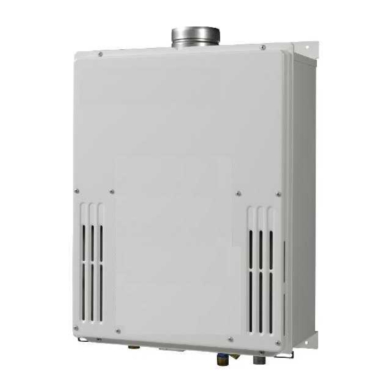
Page 4: Exterior View
CONFIDENTIAL T-M32 / T-M32 ASME Service manual Ver. 1.03 2. Exterior view Side view Front view 1 8 - 1 / 2 " ( 4 7 0 m m ) 8 - 7 / 8 " ( 2 2 6 m m ) 1 5 - 3 / 4 "... -
Page 5: Interior View
CONFIDENTIAL T-M32 / T-M32 ASME Service manual Ver. 1.03 3. Interior view... -
Page 6: List Of Main Components In The Interior View
CONFIDENTIAL T-M32 / T-M32 ASME Service manual Ver. 1.03 4. List of main components in the interior view Items# in Takagi Common parts Description components Part # For other models diagram Case assembly EM389 EM440 Manifold assembly with gas (LP model) - Page 7 CONFIDENTIAL T-M32 / T-M32 ASME Service manual Ver. 1.03 Items# in Takagi Common parts Description components Part # For other models diagram Flow sensor EKH33 T-H2-DV/OS, T-M50 EM415 (Regular model) Heat exchanger EM45C (ASME model) Gas inlet EM442 Heater EX002...
-
Page 8: Schematic Diagram
Hot water Cold water 1. When a hot water tap is opened, cold water enters the T-M32. 2. The water flow sensor detects this water flow and sends this information to computer. 3. The computer initiates fan motor and sends signal to igniter to create ignition spark. -
Page 9: Wiring Diagram
CONFIDENTIAL T-M32 / T-M32 ASME Service manual Ver. 1.03 6. Wiring diagram BK: BLACK LB:LIGHT BLUE G: GREEN O: ORANGE P: PURPLE BL: BLUE Y: YELLOW BR:BROWN W: WHITE R: RED GY:GRAY Propor- tional Water Valve Control Flow valve Sensor... -
Page 10: Wiring Diagram Checkpoints For Diagnosis
CONFIDENTIAL T-M32 / T-M32 ASME Service Manual Ver. 1.03 7. Wiring diagram check points for diagnosis Check- Parts and Description Color of wires Normal Range point White – Black (A) A, A1 100 V Power supply 90 to 110 VAC Brown –... - Page 11 CONFIDENTIAL T-M32 / T-M32 ASME Service Manual Ver. 1.03 Check- Parts and Description Color of wires Normal Range point Red - Black 4 to 5.5 VDC Flow sensor White(+) – Black(GND) 1 to 4 VDC (1,200 Pulse/min) Yellow – AFR rod More than 0.5 μA...
-
Page 12: Resistance Values Of The Temperature Thermistors
CONFIDENTIAL T-M32 / T-M32 ASME Service Manual Ver. 1.03 8. Resistance values of the temperature thermistors Resistance values at different temperatures ºF Temperature ºC Resistance kΩ 23.76 19.08 15.43 12.56 10.28 8.47 7.02 5.85 4.90 4.12 Temperature ºF ºC Resistance kΩ... -
Page 13: Operational Flow Chart
CONFIDENTIAL T-M32 / T-M32 ASME Service Manual Ver. 1.03 9. Operational flow chart Power supply ON FAV&BV open Operation SW ON Remove cause Opeartion lamp OFF Operation stop Pre-check NORMAL? False Dipswitch 031 blink settings InTH failure 321 blink OuTH failure... -
Page 14: Component Specifications
CONFIDENTIAL T-M32 / T-M32 ASME Service Manual Ver. 1.03 10. Component specifications 10-1. Burners……………………..…………………………………………….………………………..………. 15 10-2. Gas manifold…………….…………………………..…………………………………………………..16 10-3. Fan motor……………………………………………………………………….………………………...… 17 10-4. Gas valve assembly……………………………………….……………………………………….……. 18 10-5. Flame rod………………………………………………………….………………………………………… 10-6. AFR rod……………………………………………………………………………..………………………… 20 10-7. Heat exchanger……………………………………………………………..………………….……… 10-8. Flow sensor…………………………………………………………………………………………………. 22 10-9. -
Page 15: Burners
CONFIDENTIAL T-M32 / T-M32 ASME Service Manual Ver. 1.03 10-1. Burners Unit Part # #101 AOS Part # EM410 Checkpoint There are 2 types of burners in the water heater: the gas-rich burner stabilizes the flames within the combustion chamber and the air-rich burner Function produces more heat in the combustion chamber. -
Page 16: Gas Manifold
CONFIDENTIAL T-M32 / T-M32 ASME Service Manual Ver. 1.03 10-2. Gas manifold EM440 (LP model) Unit Part # #120 AOS Part # Checkpoint EM441 (NA model) 1. The manifold distributes gas from the gas valves to the burners. The manifold has two types of the nozzles: one type for gas-rich burners (20... -
Page 17: Fan Motor
CONFIDENTIAL T-M32 / T-M32 ASME Service Manual Ver. 1.03 10-3. Fan motor Unit Part # #115 AOS Part # EKK25 Checkpoint To provide combustion air into the combustion chamber and to exhaust Function flue gas. 1. Fan speed failure, causing abnormal sounds with or without combustion during operation. -
Page 18: Gas Valve Assembly
CONFIDENTIAL T-M32 / T-M32 ASME Service Manual Ver. 1.03 10-4. Gas valve assembly EM440 (LP model) Unit Part # #120 AOS Part # Checkpoint C,H1 EM441 (NA model) Opens and closes the gas pathways of the water heater (main and solenoid... -
Page 19: Flame Rod
CONFIDENTIAL T-M32 / T-M32 ASME Service Manual Ver. 1.03 10-5. Flame rod Unit Part # #106 AOS Part # EKK0E Checkpoint To detect flames while the water heater is in operation. Function 1. Unable to detect flames when flames actually do occur Failure event 2. -
Page 20: Afr Rod
CONFIDENTIAL T-M32 / T-M32 ASME Service Manual Ver. 1.03 10-6. AFR rod Unit Part # #106 AOS Part # EKK0E Checkpoint -Checks flame conditions during combustion. Function -When AFR rod detects unexpected flame conditions, the the computer of the water heater makes adjustments in the fan motor speed to compensate. -
Page 21: Heat Exchanger
CONFIDENTIAL T-M32 / T-M32 ASME Service Manual Ver. 1.03 10-7. Heat exchanger EM415 #210 (Regular model) Check (Regular model) Unit Part # AOS Part # EM45C #211 (ASME model) point (ASME model) Absorbs heat from combustion and transfer it to water through the heat Function exchanger pipes. -
Page 22: Flow Sensor
CONFIDENTIAL T-M32 / T-M32 ASME Service Manual Ver. 1.03 10-8. Flow sensor Unit Part # #429 AOS Part # EKH33 Checkpoint Detects and measures water flow rate using a spinning impeller and magnetic Function pick-up. Unable to detect or measure any water flow rate. -
Page 23: Water Control Valve
CONFIDENTIAL T-M32 / T-M32 ASME Service Manual Ver. 1.03 10-9. Water control valve (flow adjustment valve and bypass valve) Unit Part # #423 AOS Part # EKH32 Checkpoint The water control valve in the water heater has three functions of water control: flow adjustment, bypass, and two-way) This valve is exactly the same as the water valve in the T-M50. - Page 24 CONFIDENTIAL T-M32 / T-M32 ASME Service Manual Ver. 1.03 10-9. Water control valve (flow adjustment valve and bypass valve) Blue-Brown 13.0 to 16.0 VDC Color / Number of Orange-Brown ON: 12.5 to 16.0 VDC OFF: 0 to 1 VDC wires Red-Brown (0°...
-
Page 25: Thermistors
CONFIDENTIAL T-M32 / T-M32 ASME Service Manual Ver. 1.03 10-10. Thermistors #422 (Inlet) EKK38 (Inlet) E1 (Mixing) Unit Part # #433 (Output) AOS Part # EKK2T (Output) Checkpoint E2 (Output) #418 (Mixing) EX00H (Mixing) E3 (Inlet) Measure cold / hot water temperatures in the water heater. -
Page 26: Hi-Limit Switch
"111" or "121" error code will display. Error codes when hi-limit The T-M32 doesn't have the "141" error code that was used in our previous switch fails models. This error code is now replaced by the "111" and the "121" error codes. -
Page 27: Overheat Cutoff Fuse
CONFIDENTIAL T-M32 / T-M32 ASME Service Manual Ver. 1.03 10-12. Overheat cutoff fuse Unit Part # #403 AOS Part # EM387 Checkpoint The overheat cutoff fuse contains solder with a melting point of 430˚F (221˚C). Detects excessive temperatures within the water heater, especially around Function the heat exchanger and combustion chamber. -
Page 28: Freeze Protection Heaters
CONFIDENTIAL T-M32 / T-M32 ASME Service Manual Ver. 1.03 10-13. Freeze protection heaters #404 EKN86 #410 EX002 Unit Part # AOS Part # Checkpoint #415 EKK2P #426 EM45V Prevents the heat exchanger, water valves, and water pipes within the water Function heater from freezing. -
Page 29: Computer Board
CONFIDENTIAL T-M32 / T-M32 ASME Service Manual Ver. 1.03 10-14. Computer board Unit Part # #701 AOS Part # EM376 Checkpoint Controls the functions of the most parts in the water heater. Function Malfunctioning computer Failure event When the computer board failed, the control from the computer and/or the multi-system control will be abnormal. -
Page 30: Transformer
-To transform input voltage from 120 to 100 VAC. -Every electrical component of the water heater is designed to only work Function with a 100 VAC power supply, therefore, the T-M32 comes equipped with this transformer. 1. There is no power coming from the transformer. -
Page 31: Gfi
CONFIDENTIAL T-M32 / T-M32 ASME Service Manual Ver. 1.03 10-16. GFI Unit Part # #712 AOS Part # EM207 Checkpoint A,A1 -Detects electrical leakage in the water heater. Function -Stops providing power to the water heater in the case of electrical leakage. -
Page 32: Igniter
CONFIDENTIAL T-M32 / T-M32 ASME Service Manual Ver. 1.03 10-17. Igniter Unit Part # #125 AOS Part # EKN74 Checkpoint -To ignite the gas / air mixtures when the water heater is ready to burn gas Function on its burner surface. -
Page 33: Freeze Protection Thermostat
ON mode: 90 to 110 VAC and less than 1 Ω Color / Number of wires (itself) OFF mode: less than 1 VAC and more than 1 MΩ Activation and deactivation temperature of the T-M32’s freeze protection system ON mode: 36.5˚F (+6.3˚F -2.7˚F) 2.5˚C (+3.5˚C -1.0˚C) OFF mode: above 46.4˚F above 8 ˚C... -
Page 34: Surge Box
CONFIDENTIAL T-M32 / T-M32 ASME Service Manual Ver. 1.03 10-19. Surge box Unit Part # #715 AOS Part # EM385 Checkpoint A2,A3 Protects the unit from high voltage and/or high electric current caused by lightning. Function There are 2 types of surge absorbers in the water heater Surge absorber A is activated by voltage higher than 220 V, the other one is activated by voltage higher than 680 V. -
Page 35: Fault Analysis & Specifications
CONFIDENTIAL T-M32 / T-M32 ASME Service Manual Ver. 1.03 11. Fault Analysis & Specifications Remarks: 1. Proper range of values of voltage & resistance shown below. 2. Please refer to the wiring diagram for checkpoint positions. 3. Remove power to water heater when checking for continuity, disconnections, resistance values, etc. - Page 36 CONFIDENTIAL T-M32 / T-M32 ASME Service Manual Ver. 1.03 Natural of Fault Diagnosis Checkpoint 5 Check that the filter on the cold water inlet is clean. ・The hot water is not 6 Check whether or not the unit is frozen.
- Page 37 CONFIDENTIAL T-M32 / T-M32 ASME Service Manual Ver. 1.03 Natural Diagnosis Checkpoint Fault 4 Fault of PCB in the water heater ・ Fluctuation [1] No voltage to gas solenoid valve (SV of hot water Normal: 78 to 100 VDC between COM (blue) & #9 (green)
- Page 38 CONFIDENTIAL T-M32 / T-M32 ASME Service Manual Ver. 1.03 Error Code Diagnosis Checkpoint 8 Check if there is dust and lint in burner and heat exchanger, when the water heater has been installed in laundry room. 9 Check if there is grease and dirt in burner and fan motor, when the water heater has been installed in restaurant.
- Page 39 CONFIDENTIAL T-M32 / T-M32 ASME Service Manual Ver. 1.03 Error Code Diagnosis Checkpoint 6 Disconnected / damaged hi-limit switch. (Refer to section 10-11) V isual inspection: connection / breakage of wires. Normal: 1 Ω or less between blue & blue...
- Page 40 CONFIDENTIAL T-M32 / T-M32 ASME Service Manual Ver. 1.03 Error Code Diagnosis Checkpoint 5 Disconnected / damaged O.H.C.F. (Refer to section 10-12) V isual inspection: connection / breakage of wires. Error code is Normal: 1 Ω or less between blue & blue shown after 6 Check if hi-limit switch is properly functioning.
- Page 41 CONFIDENTIAL T-M32 / T-M32 ASME Service Manual Ver. 1.03 Error Code Malfunction description Cancellation method Disconnected AFR rod Turn off the power or water supply Diagnosis Checkpoint 1 AFR rod fault (Refer to section 10-6) V isual inspection: connection / breakage of wires, soot on it.
- Page 42 CONFIDENTIAL T-M32 / T-M32 ASME Service Manual Ver. 1.03 Error Code Malfunction description Cancellation method Fault of driving circuit for any of the gas solenoid valves (SV , SV , and/or SV Turn off the power supply (The computer checks the condition of the...
- Page 43 CONFIDENTIAL T-M32 / T-M32 ASME Service Manual Ver. 1.03 Error Code Malfunction description Cancellation method Pump failure Turn off the power Diagnosis Checkpoint 1 Check whether the pump connected to PCB works properly. Error Code Malfunction description Cancellation method Water control valve fault...
- Page 44 CONFIDENTIAL T-M32 / T-M32 ASME Service Manual Ver. 1.03 Error Code Malfunction description Cancellation method 1 PCB fault [1] Fault of preparation for the mixing thermistor operation. Turn off the power or water supply [2] Fault of driving circuit for Gas Proportional...
- Page 45 CONFIDENTIAL T-M32 / T-M32 ASME Service Manual Ver. 1.03 Error Code Malfunction description Cancellation method Restoring proper cable connections between all the T-M32’s and the multi-unit controller (TM-MC01). When Miscommunication between Parent and Child the computer detects proper connections units for Easy-Link systems or Multi-Unit system.
-
Page 46: Controls And Settings
CONFIDENTIAL T-M32 / T-M32 ASME Service Manual Ver. 1.03 12. Controls and settings 12-1. Diagnosis using the remote controller………………..………….….…………….….……...…..……….….……… 47 12-2. The error-call button: Verifying functionality of computer board, Displaying error code history, and Clearing error code history memory…………….………………………….…………………………. 12-3. Clearing the “101” and “991”error code…………………………………………………………………………………. 51 12-4. -
Page 47: Diagnosis Using The Remote Controller
Button 2. Scroll up or down to the needed information (mode #) of the Button T-M32 by pressing the “HOT” or “COLD” buttons. (Fig.1 shows mode #5 being selected.) When selecting information, please refer to the table on p.49 for the proper mode #. - Page 48 2. "0" will be displayed on the remote controller. (See Fig. 1) 3. Scroll to the desired T-M32 unit # in the multi-unit system or the easy-link system by pressing the "HOT" or the "COLD" buttons to scroll up or down.
- Page 49 CONFIDENTIAL T-M32 / T-M32 ASME Service Manual Ver. 1.03 Description of mode numbers in “Diagnostics Mode” Mode # Whole multi-unit system information (#0) Unit information (#1 to #20) Total system rate 0 to 9,999 (×0.1 GPM) Total operation time 0 to 9,999 (×10 hours) ON/OFF cycles 0 to 9,999 (×100 times)
-
Page 50: The Error-Call Button: Verifying Functionality Of Computer Board, Displaying Error Code History, And Clearing Error Code History Memory
1. Briefly press the “Error-call button” (do not hold down the button). 2. If the T-M32 has had prior error codes, the 7-seg LED will display the most recent error code first. Pressing the button again will display the 2... -
Page 51: Clearing The "101" And "991"Error Code
CONFIDENTIAL T-M32 / T-M32 ASME Service Manual Ver. 1.03 12-3. Clearing the “101” and “991” error code The “101” and “991” error codes signify imperfect (abnormal) combustion, caused by insufficient intake air and/or obstructions in the exhaust. If the “101” and “991” error code occurs, please check the following: 1. -
Page 52: Afr Rod Function
The AFR rod checks flame conditions during combustion. When the AFR rod detects unexpected flame conditions, the computer board of the T-M32 adjusts the fan motor speed to ensure that air and fuel are always at a proper mixture ratio, minimizing emissions. -
Page 53: Dipswitch Settings
The T-M32 shares the computer board with the T-M32 ASME. There are two banks of dipswitches (right and left bank) on the T-M32 computer board. The right bank has certain special functions as shown on the following table and generally should not need adjustment. Carefully... - Page 54 Direct vent setting Enable Disable Direct vent mode (Default) Outdoor setting Enable Disable Outdoor mode (Default) The number of priority combustion unit in a T-M32 Two priority units One priority unit Parent /Child setting on Easy-link systems Parent Child (Default)
-
Page 55: Assigning Unit Numbers In The Easy-Link System
3. Press and hold the "Unit # display" button again. New unit # will be assigned in order as you proceed through every unit. Each T-M32 in an Easy-link system is assigned a random unit #, except for the Parent unit, which is always assigned as unit #1. -
Page 56: A) On/Off Conditions: Overview
CONFIDENTIAL T-M32 / T-M32 ASME Service Manual Ver. 1.03 12-7. (A) ON/OFF conditions: Overview The following table shows the ON/OFF conditions of the water heater. ON / OFF Conditions For Every pump modes The BTU requirement is more than 14,880 BTU/h Conditions needed to turn ON. -
Page 57: B) On/Off Conditions: Btu Requirements
CONFIDENTIAL T-M32 / T-M32 ASME Service Manual Ver. 1.03 12-7.(B) ON/OFF conditions: BTU requirements alculating the ON/OFF conditions of the T-M32 A. C 【Condition needed to turn the T-M32 ON】 – T ) × GPM × 500 > 14,880 【Condition needed to turn the T-M32 OFF】... -
Page 58: A) Pump Control On / Off Condition (Only For Single And Easy-Link System)
12-8. (A)Pump control ON / OFF Conditions (Only for single and Easy-link system) To run circulation pumps efficiently and effectively, the T-M32 offers four different modes of pump control. The following table shows the pump control ON/OFF conditions for different modes. To change pump control modes, see section 12-5 for dipswitch settings. -
Page 59: B) Pump Control On/Off Conditions: Btu Requirements For Re-Circulation Mode
CONFIDENTIAL T-M32 / T-M32 ASME Service Manual Ver. 1.03 12-8. (B) Pump control ON/OFF conditions: BTU requirements for Re-circulation mode A. Calculating the ON/OFF conditions of the pump 【Condition needed to turn the pump ON】 – T ) × GPM × 500 > 14,880 【Condition needed to turn the pump OFF】... -
Page 60: Multi-Unit System On / Off Conditions
2. Condition required to reduce the number of activated T-M32’s: In the case of reducing down from two units T-M32’s to one T-M32: Flow rate = A / 1.7 All other cases: Flow rate = A × (n - 2) - Page 61 CONFIDENTIAL T-M32 / T-M32 ASME Service Manual Ver. 1.03 3. Example: Set temperature = 120˚F in a 20-unit system and priority unit is No. 1 (See the table below) To activate additional T-M32’s To reduce number of activated T-M32’s Flow rate Flow rate Unit No.
-
Page 62: Operation Time For Unit Rotation
12-10. Operation time for unit rotation The unit that turns on first is whichever unit the T-M32 decides is the primary unit. The priority unit will rotate when it reaches 100 ON / OFF cycles or after 12 hours of operation. -
Page 63: Individual Unit Operation In Multiple-System While The Multi-Unit Controller (Tm-Mc01) Is Under Abnormal Conditions (Individual Operation Mode)
See section12-5 “Individual operation mode” in Dipswitch settings of the computer board In order to make operation system effective during an abnormal condition, the number of individual unit should be half of the total number of T-M32 installed in multiple-system. -
Page 64: High Altitude Region Support Software (Fm+ And Input-)
CONFIDENTIAL T-M32 / T-M32 ASME Service Manual Ver. 1.03 12-12. High-Altitude Region Support Functions (FM+ and INPUT-) <Using this function> The high-altitude region support functions have three operation levels, with the appropriate level being set up by the installer until the abnormal sound problem is solved. -
Page 65: Checking The Flow Rate By Computer Board
CONFIDENTIAL T-M32 / T-M32 ASME Service Manual Ver. 1.03 12-13. Checking the Flow Rate by Computer Board <Function> This function offers a method for checking the flow rate in the water heater’s troubleshooting operations without having to use the remote controller. -
Page 66: Relay Selection For The Pump Control Connection
T-M32 / T-M32 ASME Service Manual Ver. 1.03 12-14. Relay selection for the pump control connection The maximum current capacity of the T-M32’s pump control connection is 1 amp. Before using relay with the pump control, please check the specifications of that particular relay to ensure that the current value through the coil will not exceed 1 amp. -
Page 67: Adjusting Manifold Gas Pressure
3. Connect a manometer to the manifold port using a tube (Figure 2). Ensure that this connection is secure enough to prevent gas leak. 4. Run water through the T-M32 to activate its operation. If presence of a gas leak is detected, immediately shut off the T-M32 and inspect the tube / manifold connection; otherwise, proceed onto the next step. - Page 68 CONFIDENTIAL T-M32 / T-M32 ASME Service Manual Ver. 1.03 desired value. 6. After gas pressure has been set, deactivate the T-M32, remove the manometer tube, and replace the port screw. Figure 1 Manifold port Figure 2 Figure 3 Tube MAX button...
-
Page 69: Manually Adjusting The Fan Motor Speed
12-16. Manually adjusting the fan motor speed While the FM+ dipswitch will automatically increase the fan speed by 7.5%, the fan motor speed on the T-M32 can also be manually adjusted. In order to perform manual adjustments to the speed, a remote controller is required. -
Page 70: Freeze Protection System
Ver. 1.03 12-17. Freeze protection system There are two features to the T-M32’s freeze protection system: the automatic fan motor system and the ceramic heating blocks. The automatic fan motor system allows the T-M32 to briefly do fan motor operation and the ceramic heating blocks will heat up whatever portion of the heat exchanger the blocks are strapped to. - Page 71 CONFIDENTIAL T-M32 / T-M32 ASME Service Manual Ver. 1.03 <Deactivate condition> When the computer checks for these temperatures during the fan motor operation as freeze protection, the Automatic fan motor system will deactivate if: > T + 3.6°F > 50°F and T >...
-
Page 72: Freeze Protection For Recirculation Systems
The T-M32 has the freeze protection function for a re-circulation system by using a pump installed in the system. Basically, this function is only ON / OFF control of the pump from the computer in the T-M32. When the computer detects the potential of the system freezing, the pump in the system starts automatically. - Page 73 Ver. 1.03 <Freeze Protection pump setting mode> To set the Freeze protection pump mode in T-M32, please follow the procedures below: 1. While in Standby mode (cannot be in combustion, forced-combustion, or FM adjustment modes), press and hold the “Increase” button for 5 seconds or longer to start a display of “A” at “7-seg LED”...
-
Page 74: Draining The Unit And Cleaning The Inlet Water Filter
12-19. Draining the unit and cleaning the inlet water filter 1. Close the manual gas shut off valve. 2. Turn off power to the T-M32, wait a few seconds. And then turn on again. 3. Wait 30 seconds for water valves starts to completely open. -
Page 75: Components Diagrams
0 0 6 0 0 8 7 0 3 0 5 0 00 2 0 5 2 0 5 2 Computer board assembly Other than Part# 706, the T-M32 and the 05 2 7 1 6 T-M32 ASME share same components. -
Page 76: Burner Assembly
CONFIDENTIAL T-M32 / T-M32 ASME Service Manual Ver. 1.03 Burner assembly The T-M32 and theT-M32 ASME share the same components. 1 0 3 1 0 2 1 0 1 40 1 1 1 3 1 5 2 1 5 3... - Page 77 CONFIDENTIAL T-M32 / T-M32 ASME Service Manual Ver. 1.03 Other than Part# 211, Part#439, Part#440 and Part# 441, the T-M32 and Water way assembly the T-M32 ASME share the same components. T-M32 4 0 1 4 1 4 4 2 0...
-
Page 78: Parts List
CONFIDENTIAL T-M32 / T-M32 ASME Service Manual Ver. 1.03 14. Parts list Item # Part # Description Common parts for other models EM389 Case assembly EM431 Front cover EM386 Air blockage plate EM104 Bracket EM384 Back guard panel T-K3, T-K3-Pro, T-K3-SP/OS, T-H2-DV/OS,... - Page 79 CONFIDENTIAL T-M32 / T-M32 ASME Service Manual Ver. 1.03 Item # Part # Description Common parts for other models EX01Z High voltage ignite cable EM409 Damper EX02C Urethane tube T-K3, T-K3-Pro, T-K3-SP, T-H2-DV/OS, T-K4-IN/OS, EKK2D Pressure port T-D2-IN/OS, T-M50 EM379...
- Page 80 CONFIDENTIAL T-M32 / T-M32 ASME Service Manual Ver. 1.03 Item # Part # Description Common parts for other models EW001 Screw M4×10 (W/Washer) EW005 Hex head screw M4×8 EW00L Pan screw M4×6 (W/Washer) EM415 Heat exchanger assembly for T-M32 Heat exchanger assembly for T-M32...
- Page 81 CONFIDENTIAL T-M32 / T-M32 ASME Service Manual Ver. 1.03 Item # Part # Description Common parts for other models T-K3, T-K3-Pro, T-K3-SP/OS, T-H2-DV/OS, EZM04 O-ring P4 EPDM (Purple) T-KJr2-IN/OS, T-K4-IN/OS, T-D2-IN/OS, T-M50 T-K3, T-K3-Pro, T-K3-SP/OS, T-H2-DV/OS, EZM16 O-ring P16 EPDM (Purple)
-
Page 82: Revisions
CONFIDENTIAL T-M32 / T-M32 ASME Service Manual Ver. 1.03 Item # Part # Description Common parts for other models “Flow sensor, Gas proportional valve EM396 connection and Thermistors” wire “Flow sensor, Gas proportional valve EM479 connection and Thermistors” wire for T-M32 ASME... - Page 83 CONFIDENTIAL T-M32 / T-M32 ASME Service Manual Ver. 1.03 15. Records of revision of this manual Version Changes Date 1.00 Sample evaluation 06/27/08 1.01 Revised by the R&D and Takagi Japan 12/09/08 1.02 Revised by the R&D and Takagi Japan 02/12/09 1.03...
Need help?
Do you have a question about the T-M32 and is the answer not in the manual?
Questions and answers