Chapters
Table of Contents

Related Manuals for A.O. Smith T-M50 ASME


Summary of Contents for A.O. Smith T-M50 ASME
- Page 1 CONFIDENTIAL T-M50 / T-M50 ASME Service manual Ver. 1.05 T-M50 / T-M50 ASME On-Demand Water Heater Service manual T-M50 A.O. Smith Water Products Company 500 Tennessee Waltz Parkway Ashland City, TN 37015 Toll Free: 1-877-737-2840...
-
Page 2: Table Of Contents
CONFIDENTIAL T-M50 / T-M50 ASME Service manual Ver. 1.05 Table of Contents 1. Specifications………………………………………...…...………….……………………...………………………… 3 2. Exterior view…………………………………………………………………………………………………………….. 4 3. Interior view….………………………………………………………………………………………………………….. 5 4. List of main components in the interior view……………….……………………………………………. 6 5. Schematic diagram………………………………………………………………………..………………………….. 8 6. Wiring diagram…………………….…………………………………………………………..………………………. 9 7. -
Page 3: Specifications
3 thermistors (In, Out, Mixing) Available remote TM-RE30 controller Central board: MC50 (Part # EM306) / PCB Model Right and left computer board:T-M50 (Part # EM307) Indicators Red LED on PCB during operation & 7-Seg LED Power supply GFI (Excluding surge absorber) control... -
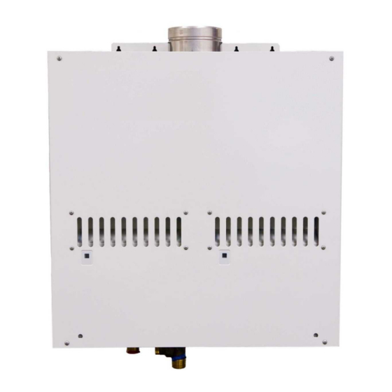
Page 4: Exterior View
CONFIDENTIAL T-M50 / T-M50 ASME Service manual Ver. 1.05 2. Exterior view Side view Front view 2 4 - 7 / 8" ( 63 2 . 9 m m ) 1 2 -1 / 4 " ( 3 1 1 . 5 mm ) 1 5 "... -
Page 5: Interior View
CONFIDENTIAL T-M50 / T-M50 ASME Service manual Ver. 1.05 3. Interior view... -
Page 6: List Of Main Components In The Interior View
CONFIDENTIAL T-M50 / T-M50 ASME Service manual Ver. 1.05 4. List of main components in the interior view Items# in Takagi Common parts Description components Part # For other models diagram Case assembly EM305 Burner assembly (Burners) EM445 T-K3, T-K3-Pro, T-K3-SP/OS,... - Page 7 CONFIDENTIAL T-M50 / T-M50 ASME Service manual Ver. 1.05 Items# in Takagi Common parts Description components Part # For other models diagram Water control valve EKH32 T-H2-DV/OS, T-M32 Water inlet EM295 Water outlet EM309 T-K3, T-K3-Pro, T-H2-DV/OS, Inlet thermistor EKK38...
-
Page 8: Schematic Diagram
1. When a hot water tap is opened, cold water enters the T-M50. 2. The water flow sensor detects this water flow and sends this information to computer. 3. The computer initiates fan motor and sends signal to igniter to create ignition spark. -
Page 9: Wiring Diagram
CONFIDENTIAL T-M50 / T-M50 ASME Service manual Ver. 1.05 6. Wiring diagram G;GREEN O:ORANGE BK:BLACK LB:LIGHT BLUE Y:YELLOW BR:BROWN P:PURPLE BL:BLUE Right side unit Left side unit Porpor- Flow Porpor- Flow tional tional Sensor Sensor Valve Valve Water Water Control... -
Page 10: Wiring Diagram Checkpoints For Diagnosis
CONFIDENTIAL T-M50 / T-M50 ASME Service manual Ver. 1.05 7. Wiring diagram check points for diagnosis Check- Parts and Description Color of wires Normal Range point White – Black (A) 100 V Power supply 90 to 110 VAC Brown – Brown (A1) - Page 11 CONFIDENTIAL T-M50 / T-M50 ASME Service manual Ver. 1.05 Check- Parts and Description Color of wires Normal Range point 1 to 15 VDC(during operation) Gas proportional valve White - red 20 to 40 Ω Red - Black 4 to 5.5 VDC Flow sensor White(+) –...
-
Page 12: Resistance Values Of The Temperature Thermistors
CONFIDENTIAL T-M50 / T-M50 ASME Service manual Ver. 1.05 8. Resistance values of the temperature thermistors Resistance values at different temperatures ºF Temperature ºC Resistance kΩ 23.76 19.08 15.43 12.56 10.28 8.47 7.02 5.85 4.90 4.12 Temperature ºF ºC Resistance kΩ... -
Page 13: Operational Flow Chart
CONFIDENTIAL T-M50 / T-M50 ASME Service manual Ver. 1.05 9. Operational flow chart Power supply ON FAV&BV open Operation SW ON Remove cause C om p o ne nt s i n t hi s c h ar t Opeartion lamp OFF... -
Page 14: Component Specifications
CONFIDENTIAL T-M50 / T-M50 ASME Service manual Ver. 1.05 10. Component specifications 10-1. Burners……………………..…………………………………………………..…………………..……… 15 10-2. Gas manifold…………….………………………………………………………..……………………..16 10-3. Fan motor………………………………………………………………………...…………………………. 17 10-4. Gas valve assembly……………………………………….…………………………………………….. 18 10-5. Flame rod………………………………………………………….………………………………………… 10-6. AFR rod……………………………………………………………………………………………………….. 20 10-7. Heat exchanger……………………………………………………………..…………………………. 21 10-8. Flow sensor…………………………………………………………………………………………………. 22 10-9. -
Page 15: Burners
Diagnostic unstable flame conditions during operation. Color/Number of wires The burner for the T-M50 has the “26Y” mark as shown below. Burner damper (#105 / EKK1P) 7 - 7 / 8 " ( 2 0 1 m m ) 9 " ( 22 9 m m) "... -
Page 16: Gas Manifold
CONFIDENTIAL T-M50 / T-M50 ASME Service manual Ver. 1.05 10-2. Gas manifold Included EM302 (LP model) Unit Part # AOS Part # Checkpoint in #114 EM303 (NA model) 1. The manifold distributes gas from the gas valves to the burners. The... -
Page 17: Fan Motor
CONFIDENTIAL T-M50 / T-M50 ASME Service manual Ver. 1.05 10-3. Fan motor Unit Part # #416 AOS Part # EKK25 Checkpoint To provide combustion air into the combustion chamber and to exhaust flue gas. Function 1. Fan speed failure, causing abnormal sounds with or without combustion during operation. -
Page 18: Gas Valve Assembly
CONFIDENTIAL T-M50 / T-M50 ASME Service manual Ver. 1.05 10-4. Gas valve assembly Included EM302 (LP model) Unit Part # AOS Part # Checkpoint C,H1 in #114 EM303 (NA model ) Opens and closes the gas pathways of the water heater (main and solenoid... -
Page 19: Flame Rod
CONFIDENTIAL T-M50 / T-M50 ASME Service manual Ver. 1.05 10-5. Flame rod Unit Part # #103 AOS Part # EKK0E Checkpoint To detect flames while the water heater is in operation. Function 1. Unable to detect flames when flames actually do occur Failure event 2. -
Page 20: Afr Rod
CONFIDENTIAL T-M50 / T-M50 ASME Service manual Ver. 1.05 10-6. AFR rod Unit Part # #103 AOS Part # EKK0E Checkpoint -Checks flame conditions during combustion. Function -When AFR rod detects unexpected flame conditions, the computer of the water heater makes adjustments in the fan motor speed to compensate. -
Page 21: Heat Exchanger
CONFIDENTIAL T-M50 / T-M50 ASME Service manual Ver. 1.05 10-7. Heat exchanger EM308 #401 (Regular model) (Regular model) Unit Part # AOS Part # Checkpoint EM323 #444 (ASME model) (ASME model) Absorbs heat from combustion and transfer it to water through the heat Function exchanger pipes. -
Page 22: Flow Sensor
CONFIDENTIAL T-M50 / T-M50 ASME Service manual Ver. 1.05 10-8. Flow sensor Unit Part # #421 AOS Part # EKH33 Checkpoint Detects and measures water flow rate using a spinning impeller and magnetic Function pick-up. Unable to detect or measure any water flow rate. -
Page 23: Water Control Valve
CONFIDENTIAL T-M50 / T-M50 ASME Service manual Ver. 1.05 10-9. Water control valve (flow adjustment valve and bypass valve) Unit Part # #418 AOS Part # EKH32 Checkpoint The water control valve in the water heater has three functions of water control: flow adjustment, bypass, and two-way) This valve is exactly the same as the water valve in the T-M32. - Page 24 CONFIDENTIAL T-M50 / T-M50 ASME Service manual Ver. 1.05 Blue-Brown 13.0 to 16.0 VDC Function Orange-Brown ON: 12.5 to 16.0 VDC OFF: 0 to 1 VDC Red-Brown (0° position) 1 VDC less The water control valve contains the flow adjustment valve and the bypass valve.
-
Page 25: Thermistors
CONFIDENTIAL T-M50 / T-M50 ASME Service manual Ver. 1.05 10-10. Thermistors #424 (Inlet) EKK38 (Inlet) E1 (Mixing) Unit Part # #405 (Output) AOS Part # EKK2T (Output) Checkpoint E2 (Output) #430 (Mixing) EKK1A (Mixing) E3 (Inlet) Measures cold / hot water temperatures in the water heater. -
Page 26: Hi-Limit Switch
"111" or "121" error code will display. Error codes when hi-limit The T-M50 doesn't have the "141" error code that was used in our previous switch fails models. This error code is now replaced by the "111" and the "121" error codes. -
Page 27: Overheat Cutoff Fuse
CONFIDENTIAL T-M50 / T-M50 ASME Service manual Ver. 1.05 10-12. Overheat cutoff fuse Unit Part # #402 AOS Part # EK333 Checkpoint The over heat cutoff fuse contains solder with a melting point of 430˚F (221˚C). Detects excessive temperatures within the water heater, especially around the Function heat exchanger and combustion chamber. -
Page 28: Freeze Protection Heaters
CONFIDENTIAL T-M50 / T-M50 ASME Service manual Ver. 1.05 10-13. Freeze protection heaters #408 EKN86 #425 EX001 Unit Part # AOS Part # Checkpoint #426 EX002 #441 EKN67 Prevents the heat exchanger, water valves, and water pipes within the water Function heater from freezing. -
Page 29: Computer Board For Burner Control
CONFIDENTIAL T-M50 / T-M50 ASME Service manual Ver. 1.05 10-14. Left/right computer boards Unit Part # #701 AOS Part # EM306 Checkpoint Controls most of the functions of the left & right combustion sections within Function the water heater. Malfunctioning computer... -
Page 30: Computer Board For Multiple Controls
1. Unable to control normal operations of the water heater. board fails 2. Unable to control multi-unit systems, which can result in T-M50 operating as individual units instead. 3. Unable to communicate other T-M50 and/or the multi-unit controller during the multi-unit system operations. -
Page 31: Transformer
CONFIDENTIAL T-M50 / T-M50 ASME Service manual Ver. 1.05 10-16. Transformer Unit Part # #718 AOS Part # EM296 Checkpoint A1,A2 -To transform input voltage from 120 to 100 VAC. -Every electrical component of the water heater is designed to only work... -
Page 32: Gfi
CONFIDENTIAL T-M50 / T-M50 ASME Service manual Ver. 1.05 10-17. GFI Unit Part # #720 AOS Part # EM207 Checkpoint A,A1 -Detects electrical leakage in the water heater. Function -Stops providing power to the water heater in the case of electrical leakage. -
Page 33: Igniter
CONFIDENTIAL T-M50 / T-M50 ASME Service manual Ver. 1.05 10-18. Igniter Unit Part # #102 AOS Part # EKN74 Checkpoint -To ignite the gas/air mixtures when the water heater is ready to burn gas on Function its burner surface. -The output voltage of the igniter is more than 14 kVDC. -
Page 34: Freeze Protection Thermostat
ON mode: 90 to 110 VAC and less than 1 Ω Color/Number of wires (itself) OFF mode: less than 1 VAC and more than 1 MΩ Activation and deactivation temperature of the T-M50’s freeze protection system ON mode: 36.5˚F (+6.3˚F -2.7˚F) 2.5˚C (+3.5˚C -1.0˚C) OFF mode: above 46.4˚F above 8 ˚C... -
Page 35: Surge Box
CONFIDENTIAL T-M50 / T-M50 ASME Service manual Ver. 1.05 10-20. Surge box Unit Part # #722 AOS Part # EM385 Checkpoint A2,A3 Protects the unit from high voltage and/or high electric current caused by lightning. Function There are 2 types of surge absorbers in the Water heater. Surge absorber A is activated by voltage higher than 220 V, the other one is activated by voltage higher than 680 V. -
Page 36: Fault Analysis & Specifications
CONFIDENTIAL T-M50 / T-M50 ASME Service manual Ver. 1.05 11. Fault Analysis & Specifications Remarks: 1. Proper range of values of voltage & resistance shown below. 2. Please refer to the wiring diagram for checkpoint positions. 3. Remove power to water heater when checking for continuity, disconnections, resistance values, etc. - Page 37 CONFIDENTIAL T-M50 / T-M50 ASME Service manual Ver. 1.05 Natural of Fault Diagnosis Checkpoint 5 Check whether or not the unit is frozen. ・The hot water is not 6 Check if there is enough gas in the tank / cylinder. (for propane...
- Page 38 CONFIDENTIAL T-M50 / T-M50 ASME Service manual Ver. 1.05 Natural Diagnosis Checkpoint Fault 4 Fault of Left and/or Right PCB ・ Fluctuation [1] No voltage to gas solenoid valve (SV of hot water Normal: 78 to 100 VDC between COM (blue) & #9 (green)
- Page 39 CONFIDENTIAL T-M50 / T-M50 ASME Service manual Ver. 1.05 Error Code Diagnosis Checkpoint 8 Check if there is dust and lint in burner and heat exchanger, when the water heater has been installed in laundry room. 9 Check if there is grease and dirt in burner and fan motor, when the water heater has been installed in restaurant.
- Page 40 CONFIDENTIAL T-M50 / T-M50 ASME Service manual Ver. 1.05 Error Code Diagnosis Checkpoint 7 Inspect flame rod [1] Check for any soot on the rod. [2] Check the connection of ground wire; make sure there is firm contact to the ground of the water heater.
- Page 41 CONFIDENTIAL T-M50 / T-M50 ASME Service manual Ver. 1.05 Error Code Diagnosis Checkpoint 5 Disconnected/damaged O.H.C.F. (Refer to section 10-12) V isual inspection: connection/breakage of wires. Error code is Normal: 1 Ωor less between blue & blue shown after 6 Check if hi-limit switch is properly functioning.
- Page 42 CONFIDENTIAL T-M50 / T-M50 ASME Service manual Ver. 1.05 Error Code Malfunction description Cancellation method Disconnected AFR rod Turn off the power or water supply Diagnosis Checkpoint 1 AFR rod fault (Refer to section 10-6) V isual inspection: connection/breakage of wires, soot on it.
- Page 43 CONFIDENTIAL T-M50 / T-M50 ASME Service manual Ver. 1.05 Error Code Malfunction description Cancellation method Fault of driving circuit for any of the gas solenoid valves (SV , SV , and/or SV Turn off the power supply (The computer checks the condition of the...
- Page 44 CONFIDENTIAL T-M50 / T-M50 ASME Service manual Ver. 1.05 Error Code Malfunction description Cancellation method Pump failure Turn off the power Diagnosis Checkpoint 1 Check whether the pump connected to central computer board works properly. Error Code Malfunction description Cancellation method...
- Page 45 CONFIDENTIAL T-M50 / T-M50 ASME Service manual Ver. 1.05 Error Code Malfunction description Cancellation method 1 Fault of Left and/or Right PCB [1] Fault of preparation for the mixing thermistor operation. Turn off the power or water supply [2] Fault of driving circuit for Gas Proportional...
- Page 46 CONFIDENTIAL T-M50 / T-M50 ASME Service Manual Ver. 1.05 Error Code Malfunction description Cancellation method Restoring proper cable connections between all the water heaters and the multi-unit controller (TM-MC01). When Miscommunication between Parent and Child the computer detects proper connections units for Easy-Link systems.
-
Page 47: Controls And Settings
12-15. High Altitude Region Support Software (FM+, FM++ and FM+++)………………………………………….. 12-16. Alarm port terminal...…………………………………………….….…………………...…………………………………….. 70 12-17. How to use the “External fan control” in T-M50…..………...……...…………..…….…………………………… 71 12-18. Relay selection for the pump control connection……………….………………………………………………….. 72 12-19. Adjusting manifold gas pressure………………...……….…………………………………………………………………... -
Page 48: Diagnosis Using The Remote Controller
CONFIDENTIAL T-M50 / T-M50 ASME Service Manual Ver. 1.05 12-1. Diagnosis using the remote controller < Individual unit> “HOT” 1. Press the "HOT" button and the "COLD" button simultaneously for “TIME” “COLD” Button at least 5 seconds to enter “Diagnostic mode”. - Page 49 2. "0" will be displayed on the remote controller. (See Fig. 1) 3. Scroll to the desired T-M50 unit # in the multi-unit system or the easy-link system by pressing the "HOT" or the "COLD" buttons to scroll up or down.
- Page 50 CONFIDENTIAL T-M50 / T-M50 ASME Service Manual Ver. 1.05 Description of mode numbers in “Diagnostics Mode” Mode # Whole multi-unit system information (#0) Unit information (#1 to #10) Total system rate 0 to 9,999 (×0.1 GPM) Total operation time 0 to 9,999 (×10 hours) ON/OFF cycles 0 to 9,999 (×100 times)
-
Page 51: Displaying Error Codes
Ver. 1.05 12-2. Displaying error codes If the T-M50 is undergoing abnormal conditions, the computer will display the error code to indicate the source of the problem. The error codes are displayed on the 7-seg LED of the central computer board and on the remote controller. - Page 52 CONFIDENTIAL T-M50 / T-M50 ASME Service Manual Ver. 1.05 B. With easy-link system installations: Example: If Unit #2 fails on the “321” error (inlet thermistor). See the picture below. Central computer board of the Parent unit: In this example, the 7-Seg LED on Parent unit will display “3”….
- Page 53 Multi-unit controller (TM-MC01): The Unit # LED on multi-unit controller will flash to inform which T-M50 has the error code. The multi-unit controller does not display the actual error codes on its 7-seg LED. The remote controller will display the error codes instead.
-
Page 54: The Error-Code Button: Verifying Functionality Of Computer Board, Displaying Error Code History, And Clearing Error Code History Memory
B. Displaying error code history 1. Briefly press the “Error-call button” (do not hold down the button). 2. If the T-M50 has had prior error codes, the 7-seg LED will display the most recent error code first. Pressing the button again will display the 2 most recent error code and so on (Computer saves a maximum of 12 error codes). -
Page 55: Clearing The "101" And "991"Error Code
CONFIDENTIAL T-M50 / T-M50 ASME Service Manual Ver. 1.05 12-4. Clearing the “101” and “991” error code The “101” and “991” error codes signify imperfect (abnormal) combustion, caused by insufficient intake air and/or obstructions in the exhaust. If the “101” and “991” error code occurs, please check the following: 1. -
Page 56: Afr Rod Function
The AFR rod checks flame conditions during combustion. When the AFR rod detects unexpected flame conditions, the computer board of the T-M50 adjusts the fan motor speed to ensure that air and fuel are always at a proper mixture ratio, minimizing emissions. -
Page 57: Dipswitch Settings Of The Left/Right Computer Boards
12-6. Dipswitch settings of the left/right computer boards The T-M50 shares the computer board with the T-M50 ASME. There is a bank of dipswitches on the T-M50’s left & right computer boards. The dipswitch functions are shown on the following table but generally do not need adjustment. -
Page 58: Dipswitch Settings Of The Central Computer Board
The dipswitch functions are shown on the following table. Carefully verify the functions of each dipswitch before changing any settings. Changing dipswitches from the factory default settings may damage the T-M50 and the system. Changing dipswitches Therefore, doing that is not recommended unless there is a very strong reason to do so. - Page 59 CONFIDENTIAL T-M50 / T-M50 ASME Service Manual Ver. 1.05 The functions of the lower dipswitch bank Functions and Dipswitch settings Output temperature settings (See table to the right) °F (Default 120 Functions ON position OFF position Activation of Individual operation mode...
-
Page 60: Assigning Unit Numbers In The Easy-Link System
3. Press and hold the "Unit # display" button again. New unit # will be assigned in order as you proceed through every unit. Each T-M50 in an Easy-link system is assigned a random unit #, except for the Parent unit, which is always assigned as unit #1. -
Page 61: A) On/Off Conditions: Overview
CONFIDENTIAL T-M50 / T-M50 ASME Service Manual Ver. 1.05 12-9. (A) ON/OFF conditions: Overview The following table shows the ON/OFF conditions of the water heater. For Every pump modes ON/OFF Conditions The BTU requirement is more than 11,900 BTU/h Conditions needed to turn ON. -
Page 62: B) On/Off Conditions: Btu Requirements
CONFIDENTIAL T-M50 / T-M50 ASME Service Manual Ver. 1.05 12-9. (B) ON/OFF conditions: BTU requirements alculating the ON/OFF conditions of the T-M50 A. C 【Condition needed to turn the T-M50 ON】 – T ) × GPM × 500 > 11,900 【Condition needed to turn the T-M50 OFF】... -
Page 63: Conditions That Stop The T-M50 From Operating
12-10. Conditions that stop the T-M50 from operating <About the dual combustion system of the T-M50> The T-M50 contains two combustion sections (left and right). The section(s) that fire on at any given time will depend on the flow rate and set temperature of the T-M50. -
Page 64: Pump Control On/Off Conditions
Ver. 1.05 12-11. Pump control ON/OFF Conditions To run circulation pumps efficiently and effectively, the T-M50 offers four different modes of pump control. The following table shows the pump control ON/OFF conditions for different modes. To change pump control modes, see section 12-7 for dipswitch settings. -
Page 65: Multi-Unit System On/Off Conditions
T-M50 / T-M50 ASME Service Manual Ver. 1.05 12-12. Multi-unit system ON/OFF conditions In Easy-link system and Multiple-system, the amount of T-M50 called on to activate depends on the FLOW RATE and the OUTPUT SET TEMPERATURE. 1. Condition required to activate an additional T-M50: Flow rate required to activate additional T-M50 = A ×... - Page 66 CONFIDENTIAL T-M50 / T-M50 ASME Service Manual Ver. 1.05 3. Example: Output set temperature = 120˚F in a four-unit system and priority unit is No. 1 (See the table below) T-M50 T-M50 T-M50 T-M50 To activate additional T-M50’s To reduce number of activated T-M50’s...
-
Page 67: Operation Time For Unit Rotation
Ver. 1.05 12-13. Operation time for unit rotation The T-M50 contains two combustion sections. The section that turns on first is whichever section the T-M50 decides is the primary section. The priority unit and section will rotate when it reaches 100 ON/OFF cycles or after 12 hours of operation. -
Page 68: Individual Unit Operation In Multiple-System While The Multi-Unit Controller (Tm-Mc01) Is Under Abnormal Conditions (Individual Operation Mode)
See section12-7 “Individual operation mode” in Dipswitch settings of the central computer board In order to make operation system effective during an abnormal condition, the number of individual unit should be half of the total number of T-M50 installed in multiple-system. -
Page 69: High Altitude Region Support Software (Fm+, Fm++ And Fm+++)
If the abnormal sound problem persists even with a “Level 3” setting, please contact our Technical Service Department. for advice. Note that there are many high risks associated with manually changing the manifold pressures. *T-M50 installation manual doesn’t mention this function for safety purposes. -
Page 70: Alarm Port Terminal
When the left/right computer(s) and/or the central computer board detect any error codes, the alarm port terminal on the central computer board will turn ON, activating the connected lamp or buzzer. < How to reset the operation> Turn off the remote controller and/or the T-M50. The current of electricity (Diagram) Maximum is 0.5 A... -
Page 71: How To Use The "External Fan Control" In T-M50
The external fan is needed when the air in the room is not enough for the combustion. T-M50 external fan motor terminals are a terminal to connect to the external fan motor. This terminal turns ON before the T-M50 start to burn. -
Page 72: Relay Selection For The Pump Control Connection
T-M50 / T-M50 ASME Service Manual Ver. 1.05 12-18. Relay selection for the pump control connection The maximum current capacity of the T-M50’s pump control connection in the central computer boar is 1 amp. Before using relay with the pump control, please... -
Page 73: Adjusting Manifold Gas Pressure
3. Connect a manometer to the manifold port using a tube (Figure 2). Ensure that this connection is secure enough to prevent gas leak. 4. Run water through the T-M50 to activate its operation. If presence of a gas leak is detected, immediately shut off the T-M50 and inspect the tube/manifold connection; otherwise, proceed onto the next step. - Page 74 7. Repeat these steps for the other combustion section. The manifold pressure on both combustion sections must be at the same value. 8. After gas pressure has been set, deactivate the T-M50, remove the manometer tube, and replace the port screw.
-
Page 75: Manually Adjusting The Fan Motor Speed
WARNING Adjusting maximum fan motor speed 1. While T-M50 is in operation, set dipswitch No.4 on left / Right Computer board to the “ON” position. (Figure 1) 2. On the temperature remote controller, display mode #3 (fan motor speed) by entering the “Diagnostics mode”... -
Page 76: Freeze Protection System
Ver. 1.05 12-21. Freeze protection system There are two features to the T-M50’s freeze protection system: the automatic fan motor system and the ceramic heating blocks. The automatic fan motor system allows the T-M50 to briefly do fan motor operation and the ceramic heating blocks will heat up whatever portion of the heat exchanger the blocks are strapped to. - Page 77 CONFIDENTIAL T-M50 / T-M50 ASME Service Manual Ver. 1.05 <Deactivate condition> When the computer checks for these temperatures during the fan motor operation as freeze protection, the Automatic fan motor system will deactivate if: > T + 3.6°F > 45°F and T >...
- Page 78 T-M50 direct-vent, which is mixed with water from the bypass valve). The automatic firing system will not activate at all unless these 2 minutes have elapsed.
-
Page 79: Freeze Protection For Recirculation Systems
<Function and Purpose> The T-M50 has the freeze protection function for a re-circulation system by using a pump installed in the system. Basically, this function is only ON / OFF control of the pump from the central computer board in the T-M50. -
Page 80: Draining The Unit And Cleaning The Inlet Water Filter
12-23. Draining the unit and cleaning the inlet water filter Close the manual gas shut off valve. 2. Turn off power to the T-M50, wait a few seconds. And then turn on again. Wait 30 seconds for water valves starts to completely open. -
Page 81: Components Diagrams
CONFIDENTIAL T-M50 / T-M50 ASME Service Manual Ver. 1.05 13. Components diagrams Case assembly Computer board assembly The T-M50 and the T-M50 ASME share the same components. 704 418 703 704 418 703 721 714... -
Page 82: Burner Assembly
CONFIDENTIAL T-M50 / T-M50 ASME Service Manual Ver. 1.05 Burner assembly The T-M50 and the T-M50 ASME share the same components. - Page 83 CONFIDENTIAL T-M50 / T-M50 ASME Service Manual Ver. 1.05 Combustion and Exhaust assembly Other than Part# 444, Part# 445, Part# 446 and Part# 447, the T-M50 and the T-M50 ASME share the same components. T-M50 ASME T-M50 ASME...
-
Page 84: Water Way Assembly
CONFIDENTIAL T-M50 / T-M50 ASME Service Manual Ver. 1.05 Water way assembly T-M50 T-M50 ASME... -
Page 85: Parts List
CONFIDENTIAL T-M50 / T-M50 ASME Service Manual Ver. 1.05 14. Parts list Item # Part # Description Common parts for other models EM305 Case assembly EM335 Brackets T-H2-DV/OS EW001 Screw M4X10 (W/Washer) EW002 Screw M4X10 (Coated) EM264 Back guard panel... - Page 86 CONFIDENTIAL T-M50 / T-M50 ASME Service Manual Ver. 1.05 Item # Part # Description Common parts for other models T-K3, T-K3-Pro, T-K3-SP/OS, T-H2-DV/OS, EKK0G Burner holder gasket T-K4-IN/OS, T-D2-IN/OS T-K3, T-K3-Pro, T-K3-SP/OS, T-H2-DV/OS, EKK2M High voltage ignite cable T-KJr2-IN/OS, T-K4-IN/OS, T-D2-IN/OS...
- Page 87 CONFIDENTIAL T-M50 / T-M50 ASME Service Manual Ver. 1.05 Item # Part # Description Common parts for other models EM267 Exhaust gasket B EM282 Case beam EM330 Exhaust auxiliary gasket EM299 Duct EM294 Duct cover EM268 Duct gasket EW003 Screw M4X10...
- Page 88 CONFIDENTIAL T-M50 / T-M50 ASME Service Manual Ver. 1.05 Item # Part # Description Common parts for other models T-K3, T-K3-Pro, T-K3-SP, T-H2-DV/OS, EKK25 Fan motor T-K4-IN/OS, T-D2-IN/OS, T-M32 T-K3, T-K3-Pro, T-K3-SP/OS, T-H2-DV/OS, EKK26 Fuse fixing plate 18 T-KJr2-IN/OS, T-K4-IN/OS, T-D2-IN/OS, T-M32...
- Page 89 CONFIDENTIAL T-M50 / T-M50 ASME Service Manual Ver. 1.05 Item # Part # Description Common parts for other models Heater 117 EKN67 T-K3, T-K3-Pro, T-K3-SP/OS, T-KJr2-IN/OS, Outlet drain plug EKK2E T-K4-IN/OS, T-D2-IN/OS T-K3, T-K3-Pro, T-K3-SP/OS, T-KJr2-IN/OS, O-ring P6 FKM EZM06...
- Page 90 CONFIDENTIAL T-M50 / T-M50 ASME Service Manual Ver. 1.05 Item # Part # Description Common parts for other models EM262 Right communication wire EM273 Remote controller terminal T-K3, T-K3-Pro, T-K3-SP/OS, T-H2-DV/OS, EM167 Wire cramp 60 T-KJr2-IN/OS, T-K4-IN/OS, T-D2-IN/OS, T-M32 EM269...
-
Page 91: Revisions
CONFIDENTIAL T-M50 / T-M50 ASME Service Manual Ver. 1.05 15. Records of revision of this manual Version Changes Date 1.00 First edition 11/26/07 1.01 Revised by the R&D and Takagi Japan 03/04/08 1.02 Revision of wrong information in section 12-14 07/02/08 1.03...
Need help?
Do you have a question about the T-M50 ASME and is the answer not in the manual?
Questions and answers