
Related Manuals for A.O. Smith TWI - 35-130


Summary of Contents for A.O. Smith TWI - 35-130
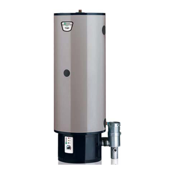
- Page 1 Condensing Stainless Steel Water Heater TWI - 35-130/45-190 Installation, User and Service Manual Innovation has a name.
- Page 2 A.O. Smith UK, Unit B8 Amstrong Mall, Southwood Business Park, Farnborough, Hampshire GU14 0NR www.aosmith.co.uk “A.O. Smith Water Heaters” is a trading name of Advance Services (Sales) Ltd. Reg.
- Page 3 Liability A.O. Smith Water Products Company does not accept any liability for claims of third parties as a result of incompetent use other than mentioned in this manual and in conformity with the General Terms and Conditions as filed with the Chamber of Commerce.
- Page 4 Instruction manual TWI 35-130 G/TWI 45-190 G...
-
Page 5: Table Of Contents
Table of content Introduction - - - - - - - - - - - - - - - - - - - - - - - - - - - - - - - - - - - - - - - - - - - - - - - 7 About the device - - - - - - - - - - - - - - - - - - - - - - - - - - - - - - - - - - - - - - - - - - 7 What to do when you smell gas - - - - - - - - - - - - - - - - - - - - - - - - - - - - - - - - - - - - 7 Regulations - - - - - - - - - - - - - - - - - - - - - - - - - - - - - - - - - - - - - - - - - - - -7... - Page 6 11.6 Claims - - - - - - - - - - - - - - - - - - - - - - - - - - - - - - - - - - - - - - - - - - - - - - - - 54 11.7 Obligations of A.O. Smith - - - - - - - - - - - - - - - - - - - - - - - - - - - - - - - - - 54 Annex - - - - - - - - - - - - - - - - - - - - - - - - - - - - - - - - - - - - - - - - - - - - - - - 55 12.1 Introduction - - - - - - - - - - - - - - - - - - - - - - - - - - - - - - - - - - - - - - - - - - - - - 55...
-
Page 7: Introduction
Introduction About the device This manual describes the installation, service and use of the TWI-device. The TWI-device is a condensating boiler with a fan in the air supply. The TWI can be installed both as a closed and as an open device. The device typically has a concentric chimney connection. -
Page 8: Target Groups
Introduction Remark Supplements or later adjustments and/or additions to any regulations, requirements and guidelines are applicable at the moment of installing. Target groups The three target groups for this manual are: • (end) users; • installation engineers; • service and maintenance engineers. Symbols indicate on every page for which target group the information is intended. -
Page 9: Notation System
Notation system This manual makes use of the following notation system: Remark Attention: important notice. Caution Ignoring this text may result in damage of the device. Warning Ignoring this text may lead to serious damage of the device and to situations that are dangerous to people. - Page 10 Introduction Chapter Target groups Description 11. Warranty (certificate) This chapter contains the terms of warranty. 12. Annexes This chapter contains the electrical circuit diagram. Instruction manual TWI 35-130 G/TWI 45-190 G...
-
Page 11: Operation Of The Device
Operation of the device Introduction This chapter will cover in the given order: • General operation of the device; • Heating cycle of the device; • Security of the device; • Safety of the installation. General operation The figure shows a cross section of the device. of the device Cross section of the device Legends IMD-0716 R0... -
Page 12: Heating Cycle Of The Device
Operation of the device In this device the cold water is supplied through the cold water inlet (16) at the bottom of the tank. The tap water heated by the combustion chamber (15) and heat exchanger (13) leaves the tank at the hot water outlet (12). If the device is maximally filled with water, there is a constant water piping pressure. - Page 13 2.4.2 Security of the water temperature The safety switch or ECO (Energy Cut-Off) switches off the device when the water temperature exceeds 95 ºC. As soon as the temperature has sufficiently dropped, the ECO is reset automatically. Contact the installation engineer if the ECO repeatedly switches off the device.
-
Page 14: Safety Of The Installation
Operation of the device Safety of the installation Apart from the standard security of the device, the installation shall further be protected using an expansion vessel, an expansion valve, a pressure reducing valve, a non-return valve and a T&P valve. The use of an expansion vessel, expansion valve and/or pressure reducing valve is dependent on the type of installation: unvented or vented. -
Page 15: Installation
Installation Warning The installation shall be carried out by an authorised installation engineer in accordance with the generally and locally applicable regulations of gas, water, electricity companies and the fire brigade. The device shall only be installed in an area that amply meets the national and local ventilation regulations (1.3 “Regulations”). - Page 16 Installation 3.3.1 Air humidity and ambient temperature The installation area should be frost-free or be protected against frost. The table gives the ambient conditions that shall be observed in order to be able to ensure the functioning of the applied electronics. Specifications for air humidity and ambient temperature Air humidity and ambient temperature Air humidity...
- Page 17 Remark When installing the device, make sure that the device cannot damage the immediate surroundings or lower floors in case of leakage of the tank and/or connections. If this is the case, install the device near a floor discharge or in a metal drip tray of the right size.
-
Page 18: Technical Specifications
Installation Technical specifications The tables below contain the technical data. 3.4.1 Dimensions of the device Top and bottom views of the device Legends See the table. 1 5 º 8 º 4 º Dimensions (all sizes in mm, unless stated otherwise) IMD-0718 - 0 7 1 8 R Dimension... -
Page 19: Gas Data
Description Unit TWI 35-130 TWI 45-190 Load Profile Energy Efficiency Class (Energy Label) Energy Efficiency Daily Electricity Consumption 0.615 0.636 Daily Fuel Consumption kWh GCV 26.476 26.550 Mixed Water 40°C (V40) ltr. ∞ ∞ Additional Load Profile Energy Efficiency Daily Electricity Consumption Daily Fuel Consumption kWh GCV Mixed Water 40°C (V40) -
Page 20: Connections Diagram
Installation Connections diagram The figure shows the connections diagram. This diagram is used in the sections describing the actual connecting activities. Connections diagram UNVENTED Legends Not mentioned numbers are not applicable. pressure reducing valve (obligatory) T&P valve (obligatory) stop valve (recommended in pipe C and obligatory in pipe A) non-return valve (obligatory) -
Page 21: Water Connections Unvented
Water connections Warning unvented The installation shall be carried out by a recognised installation engineer in accordance with the generally and locally applicable regulations (1.3 “Regulations”). 3.6.1 Cold water side See (A) in the connections diagram (3.5 “Connections diagram”). Position an approved stop valve (4) on the cold water side in accordance with the applicable regulations (1.3 “Regulations”). -
Page 22: Water Connections Vented
Installation Mount the T&P valve (3). Option: mount a temperature meter (12) for checking the temperature of the tap water. Mount a stop valve (4) in the hot water distribution piping for service purposes. If circulation piping is required, proceed by mounting the circulation piping (3.6.3 “Circulation piping”). - Page 23 Device types IMD-0531 R0 Instruction manual TWI 35-130 G/TWI 45-190 G...
- Page 24 Installation Explanation of device types Device types Description Combustion air is extracted from the installation area. Concentric and/or parallel wall flue terminal Concentric and/or parallel roof flue terminal Devices on common supply and discharge (concentric and/or parallel) in blocks of flats. Supply and discharge in different pressure area.
- Page 25 90° bends is 5. Both requirements are met. Specifications Caution A.O. Smith prescribes the use of a roof or wall flue terminal approved for the device with the C13 and C33 device types. Use of an improper roof or wall flue terminal may lead to an error.
- Page 26 TWI 35-130: Ø 125 mm TWI 45-190:Ø 125 mm (1) It is not allowed to use any other roof flue terminal. You can order the roof flue terminal mentioning the item number with A.O. Smith, manufacturer or wholesaler’s. 3.9.4 Parallel connections The table gives the maximum pipe length for parallel systems.
- Page 27 Device with parallel flue gas discharge material IMD-0533 R0 Use the longest pipe to test for the maximum length. In this case this is the flue gas discharge pipe, that has a length of 25 metres. These 25 metres are composed of the pipe material parts 1, 2, 3, 4 and 5.
-
Page 28: Electrical Connection
If this is the case, apply an isolating transformer (3.10.4 “Isolating transformer”). Please contact A.O. Smith for additional information or for ordering this isolating transformer. The figure shows a view of the electrical connector block. Instruction manual TWI 35-130 G/TWI 45-190 G... - Page 29 Connector block IMD-0534 R0 Legends screws cover plate connector block strain relief For preparation remove the cover plate (B) from the electricity part by loosening the two screws (A). Remark Consult the electrical circuit diagram for connecting the electrical components. Instruction manual TWI 35-130 G/TWI 45-190 G...
-
Page 30: Check And Adjust The Co -Value
Installation 3.10.3 Connect the mains voltage The device is delivered without power cable and main switch. Remark In order to supply voltage to the device, connect the device to the mains voltage using a permanent electrical connection. Place a double pole main switch with a contact opening of min. - Page 31 Gas control Legends Not mentioned numbers are not applicable. screws cover plate sealing cap setting screw setting hole IMD 0535 R0 3.11.1 Checking procedure Position the probe of the CO -gauge into the flue gas discharge duct of the concentric venturi tube. Open the gas supply and bleed the air from the gas system.
- Page 32 Installation 3.11.2 Adjust the CO -value For preparation remove the cover plate (2) from the electricity part by loosening the two screws (1). Remove the cap (3) from the CO setting screw (4). Insert a long screwdriver into the setting hole (5) along the air supply pipe. Correct the CO2-value dependent on the deviation by turning the CO setting screw (4).
- Page 33 Conversion to another gas category Conversion to another gas category is not possible. Instruction manual TWI 35-130 G/TWI 45-190 G...
-
Page 34: Conversion To Another Gas Category
Conversion to another gas category Instruction manual TWI 35-130 G/TWI 45-190 G... -
Page 35: Fill
Fill Connections diagram UNVENTED Legends Not mentioned numbers are not applicable. pressure reducing valve (obligatory) T&P valve (obligatory) stop valve (recommended in pipe C and obligatory in pipe A) non-return valve (obligatory) circulation pump (optional) drain valve manual gas valve (obligatory) service valve temperature meter... -
Page 36: Fill The Device
Fill Fill the device 5.1.1 Fill unvented installations Proceed as follows for filling the device: Open the stop valve (11) in the hot water pipe and (if present) the stop valves (4) of the circulation pump (6). Close the drain valve (9). Open the closest draw-off point (14). -
Page 37: Drain
Drain Connections diagram Legends UNVENTED Not mentioned numbers are not applicable. pressure reducing valve (obligatory) T&P valve (obligatory) stop valve (recommended in pipe C and obligatory in pipe A) non-return valve (obligatory) circulation pump (optional) drain valve manual gas valve (obligatory) service valve temperature meter... -
Page 38: Drain Unvented Installations
Drain Drain unvented For some activities the device needs to be drained. Proceed as follows: installations Electrically isolate the device by turning the main switch between the device and the electricity mains to the 0 position. Shut off the gas supply (10). Close the stop valve (11) in the hot water pipe. -
Page 39: Start Up
Start up Introduction This chapter will cover in the given order: • Start up. • Heating cycle of the device. Start up Start up the device by: Filling the device “Fill”). Opening the gas valve (3.5 “Connections diagram”). Switching on the voltage of the device using the main switch between the device and the electricity mains. - Page 40 Start up The electronic control will then attempt to ignite the burner again three consecu- tive times. If this has not succeeded after three times, the electronic control will temporarily switch off. The control will automatically reset after an hour and the above-mentioned cycle will be repeated until a maximum of 9 ignition attempts.
-
Page 41: Shut Down
Shut down Introduction You can: • Shut down the device for a short time; • Electrically isolate the device; • Shut down the device for a long period. Shut down the device For shutting down the device for a short time, maximally turn the thermostat for a short time counterclockwise. - Page 42 Shut down Instruction manual TWI 35-130 G/TWI 45-190 G...
-
Page 43: Errors
Errors Introduction A distinction is made between: • General errors General errors are not visible on the control. General errors are: Gas smell Insufficient or no hot water Water leakage Explosive ignition. The manual includes a table with general errors (9.2 “Troubleshooting table for general errors”). -
Page 46: Troubleshooting Table For Errors On The Control
Instruction manual TWI 35-130 G/TWI 45-190 G... - Page 47 Instruction manual TWI 35-130 G/TWI 45-190 G...
- Page 48 Instruction manual TWI 35-130 G/TWI 45-190 G...
-
Page 49: Maintenance
Maintenance 10.1 Introduction Service shall be carried out at least once a year both on the gas side and on the water side. The frequency of the maintenance depends, among other things, on the water quality, the average number of operating hours per day and the set water temperature. -
Page 50: Water-Side Maintenance
Maintenance 10.3 Water-side 10.3.1 Descale maintenance Scaling depends on the water condition and the water demand. Besides, more scale deposit will be formed in the device at high temperatures. A temperature setting of 60 ºC is recommended to ensure low scale deposit. Descale using the appropriate agents. -
Page 51: Complete Maintenance
10.4.4 Cleaning the air inlet filter 1. Dismount the air supply hose situated on the condensation drainage. 2. Take the filter out of the black housing. 3. Clean the filter by means of a vacuum cleaner or by rinsing. 4. Put the filter back into the black housing. 5. - Page 52 Maintenance Instruction manual TWI 35-130 G/TWI 45-190 G...
-
Page 53: Warranty (Certificate)
A.O. Smith will replace the entire boiler by a brand new one of similar size and quality. The replacement boiler will have a warranty that will be valid for the remaining period of the warranty for the original boiler delivered. -
Page 54: Exclusions
A claim based on the warranty provided shall be deposited with the dealer from whom the boiler was purchased or any other dealer who sells products manufactured by A.O. Smith. The investigation of the boiler as referred to in the Articles 1 and 2 will take place in an A.O. Smith laboratory. -
Page 55: Annex
Annex 12.1 Introduction This annex contains: • The Electrical circuit diagram. • Legends Instruction manual TWI 35-130 G/TWI 45-190 G... -
Page 56: Electrical Circuit Diagram
Annex 12.2 Electrical circuit diagram 0308447 1 = brown, 2 = blue, 3 = green, 4 = black, 5 = white, 6 = grey / beige Instruction manual TWI 35-130 G/TWI 45-190 G... -
Page 57: Legends Electrical Circuit Diagram
12.3 Legends WIRING = brown blue green black white orange yellow black/red black/white CLAMPING STRIP CONNECTIONS: Earth Zero Phase COMPONENTS: Electronic control Air pressure switch Hot surface igniter Temperature sensor / ECO Thermostat board Yellow LED Thermostat Red LED Green LED Gas control Transformer 120 VAC-24 VAC Fan isolating relay... - Page 58 Annex Instruction manual TWI 35-130 G/TWI 45-190 G...
-
Page 59: Index
Index air humidity 16 gas control 13 air pressure switch 13 gas smell 7 ambient conditions 15 general data 3 ambient temperature 16 general operation 11 brand names 3 heat demand 39 heating cycle 39 concentric connections 24 condition in operation 39 gas valve open 39 index 57 heat demand 39... - Page 60 Index reduction valve 14 regulations 7 safety 14 scale 50 security 11 service 10,49 service engineer 8 set the service interval 66 shut down short period 41 longer period 41 isolate 41 specifications 16 symbol installation engineer 8 service engineer 8 user 8 start up 39 target groups 8...
- Page 61 Instruction manual TWI 35-130 G/TWI 45-190 G...
- Page 62 Instruction manual TWI 35-130 G/TWI 45-190 G...
- Page 63 Instruction manual TWI 35-130 G/TWI 45-190 G...
- Page 64 Instruction manual TWI 35-130 G/TWI 45-190 G 0311935 R0...
Need help?
Do you have a question about the TWI - 35-130 and is the answer not in the manual?
Questions and answers