Table of Contents
Advertisement
Quick Links
Installa on Instruc ons and
Use & Care Guide
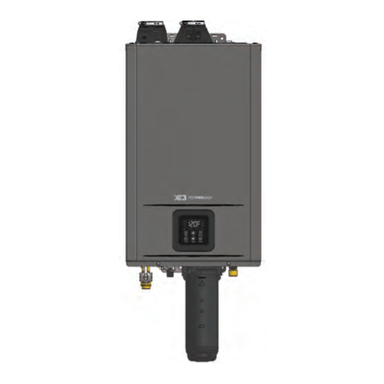
Tankless Water Heater
Residen al On-Demand Gas Tankless Water Heater
Read this manual and the labels on the water heater before you install,
operate, or service it. If you have diffi culty following the direc ons, or
aren't sure you can safely and properly do any of this work yourself:
•
Call our Technical Assistance Hotline which is listed on your warranty. We can
help you with installa on, opera ons, troubleshoo ng, or maintenance. Before
you call, write down the model and serial number from the water heater's ra ng
plate.
•
Incorrect installa on, opera on, or service can damage the water heater, your
house and other property, and present risks including fi re, scalding, electric
shock, and explosion, causing serious injury or death.
WARNING: If the informa on in these instruc ons
is not followed exactly, a fi re or explosion may
result causing property damage, personal injury or
death.
Do not store or use gasoline or other fl ammable vapors
and liquids in the vicinity of this or any other appliance.
WHAT TO DO IF YOU SMELL GAS
• Do not try to light any appliance.
• Do not touch any electrical switch; do not use any
phone in your building.
• Immediately call your gas supplier from a neighbor's
phone. Follow the gas supplier's instruc ons.
• If you cannot reach your gas supplier, call the fi re de-
partment.
Installa on and service must be performed by a qualifi ed
installer, service agency or the gas supplier.
Keep this manual with the heater for future reference whenever maintenance, adjustment or service is required.
Residen al Gas
(X3™ TECHNOLOGY available on some models)
Retain your original receipt as proof of purchase.
MODEL:
THR-160, THR-180, THR-199
LOW LEAD
CONTENT
100374994_2000628591
December 2023
Advertisement
Table of Contents

Related Manuals for A.O. Smith THR-160


Summary of Contents for A.O. Smith THR-160
- Page 1 • Do not touch any electrical switch; do not use any phone in your building. MODEL: • Immediately call your gas supplier from a neighbor’s THR-160, THR-180, THR-199 phone. Follow the gas supplier’s instruc ons. • If you cannot reach your gas supplier, call the fi re de- partment.
-
Page 2: Table Of Contents
TABLE OF CONTENT WATER HEATER BASICS ..................4 COMPONENT VIEW (X3® Model Shown) ....................4 TYPICAL INSTALLATION (X3® Model Shown)....................5 DIMENSIONS .............................6 SUPPLY CONNECTIONS ..........................7 SPECIFICATIONS ............................8 IMPORTANT SAFETY INFORMATION ..............9 RISKS DURING INSTALLATION AND MAINTENANCE ................10 RISKS DURING OPERATION ........................10 GETTING STARTED ..................12 Read Before Installa on ..........................12 Included Items ............................14 Available Accessories ..........................15... - Page 3 TABLE OF CONTENTS Dual Purpose Water Hea ng for the State of Massachuse s ..............37 X3® Technology ............................38 Pressure Relief Valve ..........................38 Electrical Connec ons ..........................40 Cascade System ............................41 OPERATION ....................43 FOR YOUR SAFETY, READ BEFORE OPERATING ..................43 Temperature Adjustment ........................46 Unit Conversion Mode ..........................47 Confi...
-
Page 4: Water Heater Basics
WATER HEATER BASICS COMPONENT VIEW (X3® Model Shown) Exhaust Port Inlet Port Heat Exchanger Igniter Air Pressure Switch Flame Sensor Igniter Rod Burner Assembly Fan Motor Assembly Venturi Assembly Pump Condensate Trap Flow Sensor Control Valve Assembly Bypass Valve Gas Valve Gas Valve Pressure Relief Valve (M Model: Field Supplied) -
Page 5: Typical Installation (X3® Model Shown)
WATER HEATER BASICS TYPICAL INSTALLATION (X3® Model Shown) Outlet Venting Inlet Air Expansion Tank Pressure Relief Valve (Drain Line not shown for clarity) Shutoff Valve Water Shutoff Valve Water Gas Line Shutoff Valve Drip Leg NOTE: Condensate Drain not shown for clarity. Residen al Gas Tankless Water Heater Use and Care Guide •... -
Page 6: Dimensions
WATER HEATER BASICS DIMENSIONS Wall Studs Dry Wall 6.58 in 16.72 cm 16.12 in 40.96 cm Water heater wall 8.31in 3.22 in 21.12 cm 8.22 cm mount contact point. Wall 5.08 in 12.90 cm 16.54 in 6.70 in 42.00 cm 17.00 cm 5.09 in 12.92 cm... -
Page 7: Supply Connections
WATER HEATER BASICS SUPPLY CONNECTIONS WALL Table 1: Supply Connec ons Item DESCRIPTION MEASUREMENT CONNECTION SIZE HOT OUTLET 9.00 in/23 cm 3/4” MNPT GAS INLET 6.90 in/17.52 cm 1/2” MNPT CONDENSATE 3.20 in/8.07 cm 1/2” MNPT COLD INLET 4.80 in/12.20 cm 3/4”... -
Page 8: Specifications
X3® Models: Comes with the X3® Scale Preven on Technology cartridge and pressure relief valve. M Models: Come with the bypass cartridge installed. All other specifi ca ons are the same. Table 2: - Specifi ca ons Model THR-160 THR-180 THR-199 Natural Gas/Propane Input BTU/h... -
Page 9: Important Safety Information
IMPORTANT SAFETY INFORMATION Read and follow all safety messages and instruc ons in this Important informa on to keep manual. Fill out this sec on and keep this manual This is the safety alert symbol. It is used to alert you to in the pocket of the water heater for poten al physical injury hazards. -
Page 10: Risks During Installation And Maintenance
IMPORTANT SAFETY INFORMATION To reduce the risk of property • Maintain the Pressure Relief Valve plumbing supplier. Follow the man- damage, serious injury or death, read properly. Follow the maintenance ufacturer’s instruc ons for installa- and follow the precau ons below, instruc ons provided by the manu- on and adjustment of the valves. - Page 11 IMPORTANT SAFETY INFORMATION To reduce the risk of unusually hot Explosion Risk • Failure to follow these instruc ons water reaching the fi xtures in the can result in serious injury or death High pressures in the house, install Thermosta c Mixing from carbon monoxide poisoning.
-
Page 12: Getting Started
GETTING STARTED Read Before Canada: it at all mes without obstruc ons. 178 Rexdale Blvd. When installed indoors, the water Installa on Toronto, ON heater can be direct vented. Canada M9W 1R3 • The length of piping between the Review all of the instruc ons Na onal Fire Protec on Associa on water heater and fi... - Page 13 GETTING STARTED • Failure to observe these warnings could result in severe personal injury, death, and/or property damage. Ven ng/Combus on: • Do not install the heater where water, debris or fl ammable vapors may get into the fl ue terminal. This may cause damage to the heater and void the warranty.
-
Page 14: Included Items
GETTING STARTED threaded connectors suitable for the • An appliance dolly or hand truck to Before you start, be sure you specifi c type of plas c pipe used: move the water heater. have the following tools and supplies: CPVC or PEX (cross-linked polyeth- Recommended Accessories ylene). -
Page 15: Available Accessories
GETTING STARTED Available Accessories Table 5: Accessories available for your Water Heater Item Descrip on Add to an M model heater to prevent scale buildup and eliminate the need X3® Cartridge for annual descaling maintenance. • P/N 100368986 Wi-Fi Module for electronically connec ng tankless water heaters to the Wi-Fi Module Kit Internet and adapter to connect to the water heater. - Page 16 GETTING STARTED Item Descrip on Neutralizer Assembly neutralizes the condensate (acidic water) that forms in the secondary heat exchanger of the water heater. It connects to the Neutralizer condensate drain port of the water heater by using connectors included Assembly Kit with the neutralizer kit.
-
Page 17: Installation
INSTALLATION Installa on Environment code in Canada, as well as applicable are for wood studs only. When local building codes. moun ng on any other surface use fasteners approved for that Proper moun ng and clearance wall material/construc on. Make Condensate Drain line The water heater shall be securely sure to level the bracket. -
Page 18: Combus On And Ven Ng Installa On
INSTALLATION Combus on Air and Example: corrosive or acid-forming chemicals such as sulfur, fl uorine, and chlorine. Ven ng Installa on Ven la on with outside air will reduce Gas Burning Appliance BTU/HR Ra ng these chemicals, but it may not Gas Water Heater 199,000 Combus on Air... - Page 19 INSTALLATION Example: B1: Determine type of For example, an installa on area that requires openings with 100 square ven la on (294,000 / 1000) x 50 = 14,700 inches of free area would need 134 There are several types of ven la on If the air volume of the room is less square inch openings if using metal that can be used:...
- Page 20 INSTALLATION Combus on Air Supply Op ons Gable vent to outdoors Outlet air to Install above 1 in (6.5 cm per 4,000 btu/h btu/h Outlet air to per 4,000 btu/h per 4,000 btu/h Alternate Air Inlet Figure 11 - Ver cal Duct Openings Figure 13 - ...
-
Page 21: Ven Ng
INSTALLATION Ven ng • Do not weld, glue, or permanently hazard. bond the vent pipe to the water • Locate the vent termina on so that WARNING! Carbon Monoxide heater’s vent collar. it cannot be blocked by any debris, Hazard. This water heater must •... - Page 22 INSTALLATION Table 7: Plas c Vent Pipe Table Item Material United States Canada Schedule 40 PVC ANSI/ASTM D1785 PVC-DWV ANSI/ASTM D2665 Exhaust pipe and Schedule 40 CPVC ANSI/ASTM F441 Fi ngs ULC S636 Cer fi ed Schedule 40 ABS-DWV ANSI/ASTM D2661 Polypropylene UL-1738 Materials Only...
-
Page 23: Installing The Vent Pipe
INSTALLATION Installing the Vent Pipe. Exhaust Vent for Clamp Indoor Installa on WARNING! Improper installa on can cause nausea or asphyxia on, ABS, PVC, CPVC or severe injury or death from carbon polypropylene vent monoxide and fl ue gases poisoning. Self-Tapping Screw Improper installa on will void The Indoor model can be vented with... - Page 24 INSTALLATION Direct Vent Installa on Example Power Vent Installa on Examples Horizontal Installation Horizontal Installation Hanger Hanger Vertical Installation Vertical Installation Roof flashing Roof flashing Fire stop Fire stop Figure 16 - Vent Confi gura ons for Direct Vent Figure 17 - Vent Confi gura ons for Power Vent 24 •...
- Page 25 INSTALLATION Table 9: - Vent Termina ons LOW PROFILE TERMINATION If used in ver cal posi on, the exhaust port must be placed in the upper side. IPEX System 1738® Vent Pipe Size PVC Kit Number IPEX PVC Part Number PVC Part Number 2"...
- Page 26 INSTALLATION POLYPROPYLENE TERMINATION TEE Vent Pipe Size Centrotherm Part Number 2" ISTT0220 3" ISTT0320 POLYPROPYLENE RADIUS ELBOWS Vent Pipe Size Centrotherm Part Number 2" 45° EXHAUST ELBOW ISELS0245UV 3" 45° EXHAUST ELBOW ISELS0345UV 2" 87° INLET ELBOW ISELS0287UV 3" 87° INLET ELBOW ISELS0387UV POLYPROPYLENE CONCENTRIC WALL TERMINATION Vent Pipe Size...
- Page 27 INSTALLATION Vent Termina on Clearances Inside corner = Vent terminal detail = Air supply inlet = Area where the terminal Fixed Operable Fixed closed closed Operable Regulator/Gas meter vent outlet Canada Installa ons US Installa ons Direct vent and other than direct vent Direct vent Other than direct vent A Clearance above grade, veranda, porch, deck, or balcony...
-
Page 28: Clearances For Sidewall Termina Ons
INSTALLATION Clearances for Sidewall Mul ple DV Sidewall Exhaust and/or direct vent sidewall termina ons should be at least 2 Termina ons Termina ons (610 mm) away from an opposite A direct vent (DV) termina on must surface/wall. Do not place the WARNING! Improper installa on be at least: termina on directly in front of an... -
Page 29: Clearances For Roo Op Termina Ons
INSTALLATION Clearances for Roo op In Canada, follow the current edi on • Intake terminals: 1 (305 mm) of B149.1, Natural gas and propane spacing between each Termina ons installa on code as well as local • Exhaust terminals: 1 (305 mm) and provincial codes. -
Page 30: Exhaust Ven Ng For Outdoor Installa On
INSTALLATION Exhaust Ven ng for INDOOR CONFIGURATION Secure the Outdoor Vent Cap to the water heater at each Outdoor Installa on corner with the screws removed earlier. See Figure 27. Turn off power and the gas supply to the water heater. Remove the four screws from the top plate of the water heater as shown in the fi... - Page 31 INSTALLATION Gas supply and Gas local and state/provincial codes, or connection. in the absence of these codes, the Pipe Sizing Install a full port manual gas current edi ons of ANSI Z223.1/ shutoff valve between the NFPA 54, Na onal Fuel Gas Code in Gas Piping water heater and the gas the USA or B149.1, Natural gas and...
- Page 32 Based on Energy Content of 1,000 BTU/ : The water heater requires 199 /h for the THR-199, 180 /h for the THR-180, 160 /h for the THR-160. The following tables are from ANSI Z223.1/NFPA 54. (Unit: Cubic feet per hour) Table 11: Natural Gas Table...
-
Page 33: Gas Conversion Instruc Ons
INSTALLATION Gas Conversion cavitate or damage the water heater's indoor installa on area is subject to heat exchanger. This equipment freezing temperatures. Insula ng Instruc ons must be installed according to its the hot water and return pipes will manufacturer's instruc ons. reduce heat loss. -
Page 34: Recircula On
INSTALLATION Recircula on as follows; the crossover valves have NOTE: These are equivalent length that includes head loss for elbows, a type of thermal valve that will Internal Pump tees, unions, etc for smooth wall open up when the water tempera- copper tube. - Page 35 INSTALLATION items should be installed per the Below is a suggested piping To reduce the risk of scalding, manufacturer’s instruc ons. diagram. Check with local codes and install Thermosta c Mixing Valves ordinances for addi onal installa on (temperature limi ng valves) at each The installer will need to consider requirements.
-
Page 36: Combina On Potable Water Hea Ng
INSTALLATION Combina on Potable personal injury or death. • Water Tubing Size, Length, and Material. Refer to the water Care must be taken by the installing Water and Space tubing manufacture for pressure contractor or design engineer to Hea ng drop informa on as it diff... -
Page 37: Dual Purpose Water Hea Ng For The State Of Massachuse S
INSTALLATION Dual Purpose Water to priori ze the domes c water valve is only required in the State system over the hea ng system. of Massachuse s. There are Hea ng for the State a wide variety of varia ons to of Massachuse s •... -
Page 38: X3® Technology
INSTALLATION X3® Technology X3® Cartridge Removal Locate the three (3) screws located in the hardware bag Disconnect power to the WARNING! DO NOT operate that is located on the top of water heater by unplugging water heater un l either the X3® the heater carton. - Page 39 THR-199 model, 180,000 BTU/h from building up inside the heat for the THR-180 model,160,000 exchanger. BTU/h for the THR-160 model, Figure 35 - Discharge Pipe • Condensate cannot be eff ec vely • The pressure relief valve needs...
-
Page 40: Electrical Connec Ons
INSTALLATION Printed Circuit Board Indoor model Remove the small tab from the ba ery that is blocking its Ba ery The water heater should be connec on. Once the tab is plugged into a 120VAC, 60 HZ removed make sure the ba ery is fully WARNING! Working on an energized electrical outlet. -
Page 41: Cascade System
INSTALLATION single harness end of the Cascade press SETTING button to enter that Make the electrical Linking Cable through the bo om and option. connec on to the water around to the circuit board. heater. Follow all local codes NOTE: C13 defines the number of NOTICE: The cable should be routed or in the absence of local codes, with Child water heaters that will be... - Page 42 INSTALLATION Child Unit Parent Unit Double Single Harness Harness Child Unit Child Unit hild Unit Child Unit Child Unit Parent Unit Cascade Linking Cable Supply Building Return Figure 39 - Mul Unit Cascade Confi gura on 42 • Residen al Gas Water Heater Use and Care Guide...
-
Page 43: Operation
OPERATION FOR YOUR SAFETY, any part has been under water. Shut-Down Instruc ons Immediately contact a qualifi ed READ BEFORE installer or service agency to Press the “ON/OFF” button OPERATING replace a fl ooded water heater. and wait for the water heater Do not a empt to repair the to shut-off. - Page 44 OPERATION Figure 40 - Ligh ng Instruc ons 44 • Residen al Gas Tankless Water Heater Use and Care Guide...
- Page 45 OPERATION Figure 41 - User Interface Display Diagram Table 14: User Interface Display Item Descrip on Water Flow Detected Pump is Opera ng Flame Detected Pump Timer 1 & 2 Ac ve Pump Bu on Time Bu on Up & Down Bu ons Opera on ON/OFF Bu on Se ng Bu on Pump Timer ON/OFF Indicators (only shown when se ng the Pump Timers)
-
Page 46: Temperature Adjustment
OPERATION Temperature Adjustment/Se ng the Temperature With the installa on steps completed, you may adjust the water heater’s temperature se ng if desired. The water temperature set point is factory set to 120°F (49°C). The temperature set point may be increased or decreased in increments by simply pressing the “UP”... -
Page 47: Unit Conversion Mode
OPERATION Unit Conversion Mode Table 15: Water Heater Temperature Set Points 120* °F °C Units of measure can be changed from Imperial to Metric and vice versa. For example, temperature can be changed from °F to °C. Flow rate will also change from gallons per minute to liters per minute when this se ng is changed. Follow this procedure to change this se ng. -
Page 48: Confi Gura On Mode (A Mode)
OPERATION Confi gura on Mode (A Mode) You can confi gure the water heater to accommodate your applica on from A Mode. Follow the procedure below to access A Mode: 1. Press and hold the SETTING bu on for 5 seconds to access A Mode. 2. -
Page 49: Se Ng The Clock
OPERATION CODE DESCRIPTION OPTIONS Number of Child Units in No Cascade System (default) Cascade System 1-11: Iden fy Number of Child Units. This ac vates the Cascade System Cascade System Heater ID Parent Heater (default) Number 2-12: Individually set each child unit per user preference Off... -
Page 50: Se Ng Recircula On Modes
OPERATION Se ng Recircula on Mode and Recircula on Type Table 20: Recircula on Mode Se ngs Ac va ng the Recircula on Modes & Se ng the Aquasta c Parameters Built-in Controller Press and hold the SETTING bu on to enter A mode. Press the UP arrow to mode A05. - Page 51 OPERATION Press the UP or DOWN bu on to scroll to the desired me delay. Press the SETTING bu on to save the se ng. Go to the next step if the se ng in A06 is 0 (recircula on with a return line). Go to step 19 if the se ng in A06 is 1 (crossover valve recircula on).
-
Page 52: Se Ng The Pump Timers
OPERATION Se ng the Pump Timers Table 21: Se ng the pump mers Se ng the Pump Timers Built-in Controller Press and hold the TIME bu on. The display will fl ash the hour value for Pump Timer 1. The Pump Timer 1 symbol and ON will be displayed. Press the UP or DOWN arrow to change the hour to the desired ac va on me. -
Page 53: Pump Timer Ac Va On
OPERATION Pump Timer Ac va on Table 22: Pump Timer Ac va on Ac va ng the Pump Timers Built-in Controller Display must be showing the set temperature. Press and release the TIME bu on. The Pump Timer 1 LED will display a er approximately 1 second. -
Page 54: Maintenance
MAINTENANCE Regular Maintenance opera ng the valve manually, Freeze Protec on System check that it will discharge in a This unit comes equipped with place for secure disposal. WARNING! Turn OFF the hea ng blocks and will auto-fi re to electrical power supply and close •... -
Page 55: Unit Draining & Power Outage
MAINTENANCE Unit Draining & Power Outage 11. Open the manual gas shutoff to the water heater. (Freeze Protec on) 12. If the set temperature is not displayed, press the ON/OFF 1. Close the manual gas shutoff bu on. valve. 2. Disconnect power to the wa- 13. -
Page 56: Troubleshooting
TROUBLESHOOTING General Troubleshoo ng Table 23: Troubleshoo ng Chart PROBLEM SOLUTIONS It takes a long me to • The me it takes to deliver hot water from the water heater to your fi xtures depends on the get hot water at the length of piping between the two. -
Page 57: Error Codes
TROUBLESHOOTING Error Codes The water heater has self-diagnos c func ons for safety and convenience when troubleshoo ng. If there is a problem with the installa on or the unit, the error code associated with that failure will be displayed on the built-in controller or remote controller. - Page 58 TROUBLESHOOTING Error Error Type Procedure Code WARNING! Working on an energized circuit can result in severe injury or death from electrical shock. 1. Check for a visible fl ame through the sight glass while water is not running through the water heater. If the error s ll occurs, immediately shut-off the water E037 False Flame Detec on heater and contact a qualifi...
- Page 59 TROUBLESHOOTING Error Error Type Procedure Code 1. Verify the inlet water temperature is not above the water heater’s set tempera- ture. 2. Remove the thermistor (do not lose the o-ring) and check for any dirt or debris. E383 Inlet Water Over-Temp. Clean with Emery cloth.
- Page 60 TROUBLESHOOTING Error Error Type Procedure Code 1. Check the pump wiring for a short or disconnec on. Correct any loose connec- ons and replace any damaged wire/connector. 2. Check the inlet fi lter for debris and clean. 3. Check the pump and water lines for debris and clear. E396 Pump - Low Speed 4.
- Page 61 TROUBLESHOOTING Error Error Type Procedure Code 1. Check the fan motor wiring. Correct any loose connec ons and replace any dam- aged wire/connector. E403 Fan - Low Speed 2. With the water heater power disconnected, check the exhaust vent and air intake piping for any blockages.
- Page 62 TROUBLESHOOTING Error Error Type Procedure Code 1. Check the fl ame sensor wire for a short or disconnec on. Correct any loose con- nec ons and replace any damaged wire/connector. 2. Check the inlet & heat exchanger thermistor sensor wires for a short or discon- nec on.
-
Page 63: Component List
COMPONENT LIST Error Error Type Procedure Code 1. Verify the water heater’s opera on is enabled. The heater’s UIM will display the set temperature when enabled. If it is disabled, press the heater’s ON/OFF bu on to enable the heater’s opera on. 2. - Page 64 COMPONENT LIST 64 • Residen al Gas Water Heater Use and Care Guide...
- Page 65 COMPONENT LIST Residen al Gas Water Heater Use and Care Guide • 65...
- Page 66 COMPONENT LIST 66 • Residen al Gas Tankless Water Heater Use and Care Guide...
- Page 67 COMPONENT LIST Residen al Gas Tankless Water Heater Use and Care Guide • 67...
- Page 68 COMPONENT LIST 68 • Residen al Gas Tankless Water Heater Use and Care Guide...
- Page 69 COMPONENT LIST When ordering repair parts, always give the following informa on: 1. Model and serial numbers. This info should be on the le side of the water heater 2. Part(s) descrip on Item Component List AIR PRESSURE SWITCH CONDENSATE TRAP BURNER DOOR HI-LIMIT FLAME SENSOR HEAT EXCHANGER THERMISTOR...
-
Page 70: Flow Rate
3% (NG) or 4.5% (LP) per 1,000 . (305 m) of eleva on increase above 2,000 . (610 m). THR Flow Rate Capacity Chart Temperature Rise (°F) THR-160 THR-180 THR-199 70 • Residen al Gas Tankless Water Heater Use and Care Guide... -
Page 71: Notes
NOTES Residen al Gas Tankless Water Heater Use and Care Guide • 71... - Page 72 Copyright © 2023, A. O. Smith. All Rights Reserved...
Need help?
Do you have a question about the THR-160 and is the answer not in the manual?
Questions and answers