
Subscribe to Our Youtube Channel
Related Manuals for Argox G Series


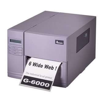
Summary of Contents for Argox G Series
- Page 1 G Series Industrial Barcode Printer User’s Manual Argox website: http://www.argox.com...
-
Page 2: Table Of Contents
Table of Contents 1. Checking Your Box Unpacking Connecting the Power Cord Parts and Features Loading Ribbon Loading Media Standard Mode Peel Off Mode Cutter Mode Adjust Position of Label Sensor 2. Printer Operation Front Panel LED Indicators Buttons LCD Display Changing Settings from the Panel Setting Display Language Rear Panel... - Page 3 Media Problems Ribbon Problems Other Problems Printer Status Transmission Problems Recovery Printer Maintenance Cleaning the Print Head Cleaning Interval Cleaning Material Cleaning Direction Cleaning the Roller Cleaning the Media Compartment 5. Technical Reference General Specifications Fonts, Bar Codes and Graphics Specification Printer Programming Language A, PPLA Interface Specifications Serial Interface...
- Page 4 Proprietary Statement This manual contains proprietary information of Argox Information Co., Ltd. It is intended solely for the information and use of parties operating and maintaining the equipment described herein. Such proprietary information may not be used, reproduced, or disclosed to any other parties for any other purpose without the expressed written permission of Argox Information Co., Ltd.
-
Page 5: Checking Your Box
1. Checking Your Box Unpacking After receiving your printer, please check for possible shipping damage: 1. Inspect the outside of both the box and the printer for possible damage. 2. Open the top cover of the printer to see if the media compartments are in order. -
Page 6: Package Contents
Package Contents Printer Power Cord Quick Guide Core for Ribbon CD Rom (including software and USB to Centronics user’s manuals) Cable... -
Page 7: Connecting The Power Cord
Connecting the Power Cord Before setting up and connecting the printer you should consider the following. WARNING! Do not operate the printer in an area where it might get wet. Find a solid flat surface with adequate room for the printer and enough space above for media and ribbon access. - Page 8 Power Switch AC Power Connector Power Jack AC Electrical Outlet...
-
Page 9: Parts And Features
Parts and Features LCD Display Top Access Door Front Access Door... - Page 10 Ribbon Pick-up Spindle Ribbon Supply Spindle Media Supply Spindle Feed Slot Thermal Print Head Bracket Thermal Print Head Head Latch Platen Roller Paper Sensor Guide...
-
Page 12: Loading Ribbon
Loading Ribbon Notes: 1. This section is applicable to transfer thermal printing. 2. Attached ribbon is with coated side in. 1. Lift the top access door and the front access door to expose the compartment. ( Figure 1 ) 2. Push the head latch by anti-clockwise, and then fold the bracket. -
Page 16: Loading Media
Loading Media G-6000 printer can be operated in three different options: standard, peel-off, or with a cutter. ■ Standard mode allows you to collect each label freely. ■ In peel-off mode, the backing material is being peeled away from the label as it is printed. After the former label is removed, the next one will be printed. -
Page 20: Peel Off Mode
Peel Off Mode Follow the common procedure of “ Loading Media “ of Standard Mode from step 1 to 3. 4. Remove approximately 6” long labels from the label backing paper ( Figure 11 ) 5. Lead the backing paper through the print head module. ( Figure 12 ) 6. -
Page 24: Cutter Mode
Cutter Mode Follow the common procedure of “ Loading Media “ of Standard Mode from step 1 to 3. 4. Insert the media into the print head module and under the paper sensor guide. ( Figure 17 ) 5. Put back the outside media guide, close the bracket, and buckle the head latch. -
Page 27: Adjust Position Of Label Sensor
Adjust Position of Label Sensor Function of the label sensor is to detect the gap, notch, or holes of labels, to help the printer for accurate print positions and label length. For labels with gaps, label sensor can be positioned wherever media locates. -
Page 28: Printer Operation
2. Printer Operation The illustrations below describe parts and features. Front Panel LCD Display LEDs and Buttons Top Access Door Front Access Door The front panel includes: 3 LED indicators (READY, MEDIA and RIBBON) 3 buttons (FEED, PAUSE and CANCEL) ... -
Page 29: Led Indicators
LED Indicators There are three LED indicators on the front panel, “READY”, “MEDIA” and “RIBBON”. These indicators display the operation status of the printer. Function READY The READY indicator will remain lighted except if any of the following conditions happens - The printer is at PAUSE status. -
Page 30: Buttons
Buttons There are three buttons, each with two basic functions. Button Function 1 Function 2 (Press the button and (Press the button) power switch together) FEED Feed a label. Perform self test & print configuration report. Pause printing. PAUSE Perform a media calibration. - Page 31 After self-test, the printer is at dump mode, If you need normal operation, you must press CANCEL to restart the printer.
-
Page 32: Lcd Display
LCD Display The model G-6000 is equipped with a LCD that displays: printer status printer settings After power-on, the LCD displays the following message as examples: READY (203,PPLA) The first parameter, 203, which stands for the printer resolution. -
Page 33: Changing Settings From The Panel
Changing Settings from the Panel You may change settings, by using the buttons on the front panel, instead of changing settings via software or commands. Buttons Function PAUSE+CANCEL Press to enter setting mode. (Don’t press over 1 second) Press again to exit setting mode and return to normal mode. - Page 34 Procedure: Turn on the printer first. 1. Till “ READY” message is displayed on the LCD, press [PAUSE]+[CANCEL] buttons simultaneously. 2. Press [PAUSE] button for several times to select the proper item that you want to change the parameter. 3. Press [FEED] button till the specified parameter appears. 4.
- Page 35 Printer LCD function settings and parameters: Item Range Factory Remarks Default CUT/PEEL -15 ~ 15 mm 0 mm Controls cut and POS (mm) peeling position. PRINT -8 ~ 15 mm 0 mm Controls vertical OFFSET print position. (mm) Positive value only. TPH VER -3 ~ 3 mm 0 mm...
- Page 36 enabled. BASE 0 mm DARKNESS Notes: 1. To make sure the settings take effect you had better restart the printer after changing them. 2. When you store graphics with compression in flash board, do not use them under non-compression mode. They must be consistent.
-
Page 37: Setting Display Language
Setting Display Language The printer supports six languages, English, French, German, Italian, Spanish and Portuguese for LCD display. To select the language 1. Press PAUSE and CANCEL buttons at the same time. 2. Hold both buttons for about 3 seconds. 3. -
Page 38: Rear Panel
Rear Panel The rear panel includes: -An 8-bit DIP switch - A 36-pin Centronics parallel port - A 9-pin RS-232 serial port - A PS/2 keyboard interface - A power switch and a power connector... -
Page 39: Dip Switch
DIP switch You may configure the printer by setting DIP switches. Once the setting is changed, please restart the printer by turning the power OFF then turn ON again. Position Switch Function Thermal transfer printing mode. Ribbon detection is enabled. Direct printing mode. -
Page 40: Media Calibration
Media Calibration After the first time of installation, the printer media is changed or the media sensor board is replaced, the media sensor calibration must be performed. 1. Load the media (and ribbon for thermal transfer printing) properly. 2. Shift the media sensor to proper position. 3. -
Page 41: Printing A Configuration Report
Printing a Configuration Report To perform a self-test and print a configuration report, helping to check printer’s print quality and internal settings. Steps as below: 1. Turn off the printer. 2. Load media and ribbon. 3. Press and hold the FEED button while turning on the power. -
Page 42: Resetting To Factory Default Settings
Resetting to Factory Default Settings If you would like to reset the printer to its factory defaults after certain commands have been sent or settings changed: 1. Turn off the printer. 2. Press and hold the CANCEL button, and turn on the power. -
Page 43: Computer Connections
3. Computer Connections The printer comes with a standard Centronics parallel interface, and a nine-pin Electronics Industries Association (EIA) RS-232 serial data interface. Connecting the Printer 1. You can connect the printer with any standard Centronics cable to the parallel port of the host computer. 2. -
Page 44: Communicating With The Printer
Windows XP; steps in other versions of operation systems are similar. Drivers can be installed via the CD-Rom included in printer package; or it can be downloaded from Argox website >> Technical Support >> Download Center >> select product model... -
Page 45: Installing A Printer Driver
Installing a Printer Driver 1. Turn off the printer. Plug the power cable into the power socket on the wall, and then connect the other end of the cable to printer's power socket. Connect the Parallel cable, Serial cable, or Ethernet cable to the proper port on the printer and on your computer. - Page 46 3. Choose Industrial Barcode Printers on the screen, go to G-6000 product page, click on version of Seagull driver and then start installation:...
- Page 47 Instead of the flash prompt above, another way to install Seagull driver is to run the DriverWizard utility from the Installation Directory where the Seagull driver files locates. 4. On the prompt, Windows Printer Driver, select “I accept…” and click "Next". 5.
- Page 48 6. Click "Finish". 7. Select Install printer drivers and Click "Next"...
- Page 49 8. Select model & emulation – G-6000 PPLA: Argox G-6000 PPLA 9. Select the port of the printer and click "Next".
- Page 50 10. Enter Printer name (i.e. Argox G-6000 PPLA) and select "do not share this printer”, and click "Next". Argox G-6000 PPLA 11. Check all the data on the showing screen, if it is correct, click "Finish". Argox G-6000 PPLA Argox G-6000 PPLA...
- Page 51 12. After the related files have been copied to your system, click "Finish". Installing Printer “Argox G-6000 PPLA”… 13. After driver installation is complete, click "Close". The driver should now be installed. Installed Printer Argox G-6000 PPLA...
-
Page 52: Troubleshooting
4. Troubleshooting Normally, if the printer is in not working properly, the "READY" LED blinks continuously, and printing and communication between the host and printer stops. LED and LCD Diagnosis Blinking LEDs indicate a problem. Check the LEDs and the LCD display and refer to the following solutions: Media Problems LED/LCD... -
Page 53: Ribbon Problems
Ribbon Problems LED/LCD Indication READY and RIBBON LEDs Blinking LCD Display RIBBON OUT Possible Problems Solutions Remarks Ribbon out Supply the ribbon roll Not applicable to direct thermal. Ribbon jam Recover the jam Ribbon sensor error Replace ribbon sensor Note: If you use direct thermal, set bit 1 of DIP switch to OFF. Other Problems Indication READY LED... - Page 54 Check the media. Cutter failed DIP switch bit 3 should be ON for Check the connection cutter. between cutter and main board. Call for service. Check the graphics and Memory full soft fonts from host. Make sure to delete the graphics and soft fonts if they are no longer used by the application...
-
Page 55: Printer Status
Printer Status LCD Display Blinking Description PAUSE READY Printer is paused. Press PAUSE or CANCEL to return to normal operation mode. MEDIA OUT MEDIA Media is uninstalled or used up. Load new media to the printer. READY RIBBON OUT RIBBON Ribbon is uninstalled or end-of-ribbon occurred. -
Page 56: Transmission Problems
Transmission Problems If the host shows "Printer Time out" 1. Check if the communication cable (parallel or serial) is connected securely to your parallel or serial port on the PC and to the connector on the printer at the other end. 2. -
Page 57: Printer Maintenance
Printer Maintenance Vertical streaks in the printout usually indicate a dirty or faulty print head. (Refer to the following examples.) Clean the print head. If the problem persists, replace the print head. For unstable ribbon roll rotation, check the label path and make sure the head latch is securely closed. -
Page 58: Cleaning The Print Head
Cleaning the Print Head To keep the Print Head remain in the best conditions and efficiency and to extend duration for use, regular cleaning action is needed. Note: Turn off the printer before cleaning. Clean the print head as follows: 1. -
Page 59: Cleaning Direction
It’s strongly recommended to wear hand gloves during cleaning progress. Do not touch print head surface by bare hands or with any hard equipment. Water or spit should be kept away in case of corrosion on heating elements. Cleaning Direction When cleaning the print head, always wipe in One-Way Direction - from Left to Right only, or, from Right to Left only, to clean “Heating Line”... -
Page 60: Technical Reference
5. Technical Reference General Specifications G-6000 Printing Direct Thermal / Thermal Transfer Method Printing 203 dpi (8 dots/mm) Resolution Printing Max 6.6” (168mm) Width Printing Max. 30” (7620 mm) Length Printing 2 ~ 6 IPS (51~152 mm/s) Speed Memory 2MB DRAM, 1MB Flash ROM CPU Type 32 bit RISC CPU Media gap &... - Page 61 Roll-feed, die-cut, continuous, fan-fold, tags, Media Type ticket in thermal paper or plain paper, fabric labels Max Width: 6.3”(160mm) Min Width:1”(25.4mm) Thickness: 0.0025”~0.01”(0.0635~0.254mm) Media Max roll capacity(OD): 8”(203mm) Core size: 1.5” ~ 3” (38~76mm) ID Ribbon Width: 1”~6.1” Ribbon roll – max OD: 2.5”(63mm) Ribbon Length: max 360m Ribbon Core size –...
- Page 62 Cutter, Dispenser Kit, RTC Card, 2MB Asian Options and Font Card(Traditional Chinese, Simplified Accessories Chinese, Korean and Japanese), ArgoKee Agency CE, cULus, FCC class A, CCC, RoHS Listing Note: Since Font Card and optional RTC Card share the same slot on G-6000 main board, they cannot be used at the same time.
-
Page 63: Fonts, Bar Codes And Graphics Specification
Fonts, Bar Codes and Graphics Specification The specifications of fonts, bar codes and graphics depends on the printer emulation. The emulation is a printer programming language through which the host can communicate with your printer. Printer Programming Language A, PPLA Specification G-6000 Courier (including PC Set, Legal, ECMA94... -
Page 64: Interface Specifications
Interface Specifications This section presents the interface specifications of IO ports for the printer. These include pin assignments, protocols and detailed information about how to properly interface your printer with your host or terminal. Serial Interface The RS-232 connector on the printer side is a female, DB-9. Signal Description No function... -
Page 65: Connection With Host
Connection with Host Host 25S Printer 9P Host 9S Printer 9P (PC or compatible) (PC or compatible) DTR 20 …… 1 DSR …… 1 DSR DTR 4 …… 6 DTR …… 6 DTR DSR 6 DSR 6 …… 2 RX ……... - Page 66 The simplest way to connect to other hosts (not PC compatible) or terminals is: Printer Terminal/Host Pin 2- RxData ……… TxData Pin 3- TxData ……… RxData Pin 5- Ground ……… Ground In general, as long as the data quantity is not too large and you use Xon/Xoff as flow control, it will be problem free.
-
Page 67: Parallel (Centronics)
Parallel (Centronics) The parallel port is a standard 36-pin Centronics connector. Pin assignments are as follows: Pin Direction Definition Direction Definition /STROBE SELECT Data1 14,15 Data 2 Ground Data3 Ground Data4 Data5 19~30 Ground Data6 Data7 /Fault Data8 33~36 /ACK BUSY Auto Polling Both the serial port and parallel port of this printer can be active at... -
Page 68: Ascii Table
ASCII TABLE " XOFF & ‛ < >... -
Page 69: Accessory
6. Accessory Note: The printer electronics are susceptible to static discharge. Wear an anti-static wrist and attach it to the printer chassis. Cutter Installation 1. Turn off the printer power. 2. Remove the top covers on both left and right sides. 3. - Page 70 5. Remove the tear-off bracket (5) by releasing screws (4) shown in Figure below.
- Page 71 6. Thread the cutter cable (8) through a hole and route to JP13 connecter (CUTTER) on the main board.
- Page 72 7. Insert the left side of cutter bracket (7) and secure screws (6) to the TPH module.
- Page 73 Load the media and the ribbon after the cutter is proper installed. The following procedure is taken at first time after installation or cutter jam. 1. Put the media end on the roller. 2. Close the TPH latch. 3. Hold PAUSE/CALIBR. button then turn on power switch. 4.
-
Page 74: Dispenser & Rewinder Installation
Dispenser & Rewinder Installation Turn off the power switch. 2. Remove top covers on both left and right sides. 3. Set bit 5 of DIP switch to “ON” position. 4. Assemble the related components for both left and right sides. Refer to the Figure below. - Page 75 5. Connect the dispenser sensor assembly to JP12 (LABEL) on main board and secure the dispenser board in front of TPH module. 6. Install ribbon and media.
Need help?
Do you have a question about the G Series and is the answer not in the manual?
Questions and answers