Table of Contents
Advertisement
Quick Links
IDEAL INDUSTRIES, INC.
TECHNICAL MANUAL
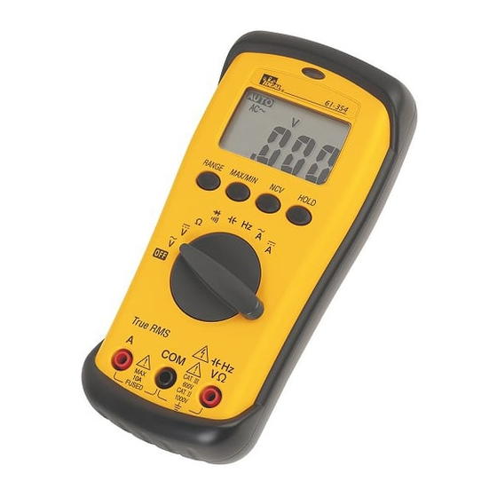
MODEL: 61-354 (TRMS)
The Service Information provides the following information:
Precautions and safety information
●
Specifications
●
Basic maintenance (cleaning, replacing the battery and fuses)
●
Performance test procedures
●
Calibration and calibration adjustment procedures
●
Form number: TM61354
Revision: 2. Date: July 2006
Form number TM61354
Rev 2 July 2006
Advertisement
Table of Contents

Subscribe to Our Youtube Channel
Related Manuals for IDEAL 61-354 (TRMS)


Summary of Contents for IDEAL 61-354 (TRMS)
- Page 1 IDEAL INDUSTRIES, INC. TECHNICAL MANUAL MODEL: 61-354 (TRMS) The Service Information provides the following information: Precautions and safety information ● Specifications ● Basic maintenance (cleaning, replacing the battery and fuses) ● Performance test procedures ● Calibration and calibration adjustment procedures ●...
-
Page 2: Table Of Contents
TABLE OF CONTENTS Title Page Introduction Precautions and Safety Information Symbols Safety Specifications General Specification Measurement Characteristics Voltage Specification Current Specifications Resistance, Diode, Frequency Specifications Capacitance Specification Auto Power Off, Display Auto Power Off Disable Auto Power Off Physical and environment characteristics Certification and compliance Required Equipment Basic Maintenance... -
Page 3: Introduction
The 61-350 serials contain parts that can be damaged by static discharge. Follow the standard practices for handling static sensitive devices. For additional information about IDEAL INDUSTRIES, INC. and its products, and services, visit IDEAL INDUSTRIES, INC. web site at: www.idealindustries.com... -
Page 4: Safety
Page 2 SAFETY Review the following safety precautions to avoid injury and prevent damage to this product or any products connected to it. To avoid potential hazards, use the product only as specified. CAUTION These statements identify conditions or practices that could result in damage to the equipment or other property. -
Page 5: Specifications
Page 3 SPECIFICATIONS All specifications are warranted unless noted typical and apply to the 61-354. Stated accuracies are at 23°C±5°C at less than 80% relative humidity and without the battery indicator displayed. General specifications Characteristics Description Display count 3 1/2 Numeric update rate 1.5 times / sec Polarity display... -
Page 6: Measurement Characteristics
Page 4 Measurement Characteristics Accuracy is ±(% reading + number of digits) at 23°C ± 5°C, less than 80% R.H. (1) DC Volts Over voltage Range Resolution Accuracy protection 200mV 100µV ±(0.5% reading + 2 digits) DC 1000V 10mV 200V 100mV 1000V Input Impedance: 10MΩ... -
Page 7: Resistance, Diode, Frequency Specifications
Page 5 (5) Resistance Over voltage Range Resolution Accuracy protection 200Ω 0.1Ω 2KΩ 1Ω ±(0.7% reading + 3 digits) 20KΩ 10Ω 600V rms 200KΩ 100Ω 2MΩ 1KΩ ±(1.0% reading + 3 digits) 20MΩ* 10KΩ ±(1.5% reading + 3 digits) Open circuit Voltage: -1.3V approx. * <100 dgt of reading rolling. -
Page 8: Capacitance Specification
Page 6 (8) Capacitance Over voltage Range Resolution Accuracy Protection 20nF 10pF 200nF 100pF 2μF ±(1.9% reading + 8 digits) 600V rms 20μF 10nF 200μF 100nF 2mF* 1μF * <100 dgt of reading rolling. (9) Auto Power Off (APO) If the meter idles for more than 10 minutes, the meter automatically turns the power off. When this happens, the state (non-logic measurement) of the meter is saved, the meter can be turned back on by pressing any switch or changing the rotary switch. -
Page 9: Physical And Environment Characteristics
Page 7 Physical and Environmental Characteristics Characteristics Description 2.9 Inch×6.14 Inch×1.34 Inch (without holster) Dimensions (H×W×D) 3.15 Inch×6.45 Inch×1.73 Inch (with holster) Weight (with battery) 0.25Kg With holster 0.35Kg Environmental characteristics Description Temperature operating 0 to +50°C Non-Operating -20 to +60°C Humidity (operating) <80% R.H. -
Page 10: Required Equipment
Page 8 Required Equipment Required equipment is listed in Table B. If the recommended models are not available, equipment with equivalent specifications may be used. Repairs or servicing should be performed only by qualified personnel. Table B. Required Equipment Equipment Required Characteristics Recommended Model AC Voltage Range: 0 ~ 750V AC... -
Page 11: Basic Maintenance
Page 9 Basic Maintenance Warning To avoid shock, remove the test leads and any input signals before opening the case or replacing the battery or fuses. Opening the Meter Case Caution To avoid unintentional shock, always place the uncovered Meter assembly on a protective surface. When the case of the Meter is open, circuit connections are exposed. -
Page 12: Testing Fuses
Page 10 Testing Fuses To test the internal fuses of the meter. 1. Turn the rotary selector switch to the Ω position. 2. To test FS1, plug a test lead into VΩHz input terminal, and touch the probe to the A input terminal. The display should indicate between 0.0 to 0.2Ω. -
Page 13: Performance Tests
Page 11 Performance Tests The following performance tests verify the complete operability of the Meter and check the accuracy of each Meter function against the Meter’s specifications. Accuracy specifications are valid for a period of one year after calibration, when measured at an operating temperature of 18°C to 28°C and a maximum of 80% relative humidity. -
Page 14: Testing The Voltage Function
Page 12 Testing the Voltage Function To verify accuracy in the AC and DC voltage ranges, do the following: 1. Turn the rotary switch to “V ” position. 2. Connect the Calibrator to the VΩHz and COM inputs on the Meter. 3. -
Page 15: Testing The Resistance Function
Page 13 Table 3 Ω Resistance Test: Step Source Reading 150.0Ω 148.6Ω to 151.4Ω 1.500KΩ 1.486KΩ to 1.514KΩ 15.00KΩ 14.86KΩ to 15.14KΩ 150.0KΩ 148.6KΩ to 151.4KΩ 1.500MΩ 1.482MΩ to 1.518MΩ 15.00MΩ 14.74MΩ to 15.26MΩ Lead resistance on the 200Ω range is not included in error. Testing the Capacitance Function The Meter measures capacitance by charging the capacitor with a known direct current, measuring the resultant voltage, and calculating the capacitance. -
Page 16: Testing The Ac Current Function
Page 14 Testing the amp (A) Function To verify the accuracy of AC current measurement functions, do the following: 1.Connect the Calibrator to the A and COM inputs on the Meter. 2. Turn the rotary switch to A 3. Apply the inputs for steps 1-4 in Table 5. 4. -
Page 17: Calibration
Page 15 Calibration Procedure Recalibrate your meter: It is recommended that the multimeter be calibrated once each year. 1. Perform calibration at an ambient temperature of 23°C±2°C and a relative humidity of 75% or less. 2. Disconnect the test leads and turn the meter off. Remove the test leads from the front terminals. 3. -
Page 18: Calibration Adjustment Points
Page 16 VR67 VR68 VR66 Figure 5 61-354 Calibration Adjustment Points Form number TM61354 Rev 2 July 2006... - Page 19 Page 17 Form number TM61354 Rev 2 July 2006...
Need help?
Do you have a question about the 61-354 (TRMS) and is the answer not in the manual?
Questions and answers