Table of Contents
Advertisement
Advertisement
Table of Contents

Related Manuals for Acom 2000A


Summary of Contents for Acom 2000A
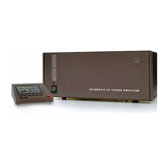
- Page 1 AUTOMATIC HF LINEAR AMPLIFIER...
- Page 2 ACOM OOD Blvd. Nikola Mushanov 151 1330 Sofia, Bulgaria phone: +359 2 920 96 55 fax: +359 2 920 96 56 e-mail: acom@acom-bg.com acom@mail.orbitel.bg www.acom-bg.com...
-
Page 3: Table Of Contents
Table of Contents 1. GENERAL INFORMATION ........3 1-1. - Page 4 6-5. CLEAR THE USER TUNINGS ......30 6-6. CLEAR THE MEMORY ........31 7.
-
Page 5: General Information
If assistance is needed, you should contact your local dealer. If necessary, your dealer will contact ACOM for additional guidance. If you still have an issue you need to discuss with one of ACOM's specialists, the contact information is as follows: fax: + 359 2 920 96 56, e-mail: acom@acom-bg.com, acom@mail.orbitel.bg or by mail: blvd.”Nikola Mushanov”... -
Page 6: Safety Considerations, Explicit Definitions
• Uses two 4CX800A (GU74B / ГУ74Б) Svetlana (Светлана) high performance ceramic-metal tetrodes with plate dissipation of 800W each (forced air cooling, grid-driven). • ACOM maintains strict adherence to the tube manufacturer’s specifications for cooling and for the sequence of applying and removing the different tube voltages. Starting filament current is limited, and there is constant monitoring and protection of all supply voltages and currents. - Page 7 system for safe operation. The amplifier is designed to meet international safety standards and complies with CE safety and electromagnetic compatibility requirements, as well as FCC regulations. This operating manual contains information, precautions, indications for cautions and warnings which must be followed by the user to ensure safe operation and to keep the ACOM2000A in safe operating condition.
-
Page 8: Installation
2. INSTALLATION 2-1. Unpacking and Initial Inspection N O T E Before you start any action on installing the amplifier, thoroughly read through this manual. First, carefully inspect both cardboard cartons and their contents for physical damage. If damage is apparent, notify your dealer immediately. Delay may infringe carrier's warranty conditions. -
Page 9: Transformer Installation
Normally the amplifier is supplied with Voltage Selector set for a nominal mains voltage of 240V. There might be exceptions in cases of special delivery and then the voltage set is noted in the Table of Individual Data (Table 2-1). If your mains has a different nominal voltage, it will be necessary for you to contact your dealer or see the TECHNICAL SUPPLEMENT for details. -
Page 10: Connections
Move the transformer, using its rope sling handle, into the compartment. Take care not to damage the wiring or components and position the transformer so that the captive nuts are aligned with the corresponding chassis holes. Make sure that the transformer is centered. The transformer bolts must be installed NOW for safe operation. - Page 11 Fig.2-3 Amplifier Remote Control Unit Connections Fig.2-4 Main Unit, RCU, Antenna Selector, and Transceiver connections...
- Page 12 C A U T I O N Do not use your transceiver’s internal tuner with the 2000A –this can damage the input of the 2000A c) Connect a coaxial cable from the amplifier output (on the rear panel, marked RF OUTPUT)
- Page 13 Check with your dealer for cable options for your transceiver. h) Automatic antenna selector ACOM 2000S can be connected to the respective connector on the RCU rear panel.
-
Page 14: Installation Of Optional Fan
W A R N I N G Before connecting the amplifier to your mains supply, be sure that the supply is correctly wired, and is adequate for the current drawn by the amplifier. Make certain that the grounding lead is connected properly in the wall outlet for the amplifier. - Page 15 Fig.3-1 Remote Control Unit (RCU) N O T E The owner's call sign will be only displayed after it has been programmed into the RCU. See Section 6-1 for details on programming your callsign. In this condition, only the RCU is operational, while the amplifier itself is still fully off. Nevertheless, you have access to the HELP feature (at the left bottom corner, see S5.6) and you can switch antennas if the ACOM2000S automatic antenna selector and the ACOM2000SW remote antenna switch are installed.
- Page 16 Fig.3-2 Menu Structure (see also S.10) N O T E We recommend that before powering up the amplifier for the first time, you familiarize yourself with the functions of the RCU in the OFF menu. The available controls and indications seen on the RCU are similar in both the OFF and MAIN menus.
-
Page 17: Auto Mode
4. AUTO MODE Operation of the 2000A amplifier is simplified a great deal due to the high degree of automation. You can start operation immediately after it is installed. However, to make full use of its possibilities and to fully configure the amplifier we recommend that you thoroughly read the following information. - Page 18 Fig.4-1 RCU display during warmup A 2.5 minutes tube warm-up period follows during which heater and bias voltages are applied. During warm-up the amplifier remains in STB, so you can operate with the transceiver only. You can also change the antennas manually or read the HELP texts during the warm-up period. N O T E When you intend to have a brief pause in operating (e.g.
- Page 19 Fig.4-2 RCU display - MAIN MENU The RCU display provides information about the current operational condition of the amplifier. You can see three bar graphs: Forward Power, Reflected Power (RFL) and Exhaust Air Temperature. Unless transmitting, only the last one is active, indicating the Exhaust Air temperature in degrees The whole HF spectrum is divided into 250 segments.
- Page 20 the two is the real output power delivered from the amplifier. The red TX sign illuminates (See fig 4-3) whenever KEY-IN input is keyed, i.e. the transceiver goes into transmit mode. If the CAT connection is active and the amplifier is in OPERATE mode, it will continuously track the transceiver frequency and will automatically tune up when entering a new segment.
-
Page 21: Auto Tune Procedure
. If you don’t have the Automatic antenna selector ACOM 2000S (and ACOM 2000SW remote antenna switch) installed, pushing these buttons would change only the settings stored in the amplifier memory for each antenna. e) TURNING OFF In order to turn the amplifier off, press the red ON/OFF button on the RCU. - Page 22 C A U T I O N Using a feeder of coaxial cable at VSWR > 3:1 on HF bands is not recommended. At such high values of VSWR, the high voltages, high currents, and heat associated with line losses, risk permanently damaging the coaxial cable.
- Page 23 The amplifier will wait for you to apply between 10 and 20W continuous (CW) carrier signal on the desired frequency. If you don’t begin transmitting within 40 seconds, the amplifier will return back to the MAIN menu. The automatic matching process starts the moment power remains constant within the indicated boundaries.
-
Page 24: Erasing User Segments (Return To Default- Tunings)
- If the transceiver is FT-450, FT-950, FT-2000, FT-3000, FT-5000, FT-9000, IC-756PROIII, IC- 7410, IC-7600, IC-7700, IC-7800, K3, TS-480, TS-590, TS-990, TS-2000, or another modern CAT protocol enabled radio, you need only to push the RCU TUNE button. ACOM 2000A will do the rest by itself. -
Page 25: Manual Modes
5. MANUAL MODES Pushing the SET/EXIT key while in main menu will get you to the MANUAL MODE: Fig.5-1 RCU display - MANUAL MODE Now you have access to some functions, procedures, and settings, which are marked on the soft key prompting labels. 5-1. -
Page 26: Measure Function
Fig.5-2 RCU display - MANUAL TUNE In figure 5-2, graphical representations of the physical positions of the Tune (STEP 101) and Load (STEP 35) capacitors are depicted above their respective TUNE and LOAD dual-arrow adjustment buttons. The arrows indicate which way the automatic procedure would move the motor (they are correct only at drive power of 5 to 50W). - Page 27 Fig.5-3 RCU display - MEASURE With the up and down buttons you can select the item to be measured (listed in an alphabetic order). During measuring, the amplifier can be used and controlled in OPR or STB modes, to transmit and change the frequency segment and antenna if a new frequency is applied to it.
-
Page 28: Service Procedure
5-3. SERVICE procedure The procedure SERVICE can be selected and used only in STB mode. It is used for adjustment of the zero-signal plate current and the optical sensors disks during repair. We recommend this procedure to be carried out only by a trained service technician. Fig.5-4 RCU display - SERVICE When selecting TUNE, LOAD or BAND, the respective motor can be moved step by step CCW or CW with the left and right arrow buttons. -
Page 29: More Settings
Fig.5-5 RCU display – CAT SETTINGS A transceiver that is not included in the list still could be CAT connected to the 2000A if its protocol is compatible with any of the listed transceivers. Select KENWOOD NEW if your transceiver is TS-570, TS-870, TS-480, TS-590, TS-990, TS- 2000 or newer. - Page 30 a) LOCK Once locked through this option, the amplifier can be switched on, but it will not turn into OPERATE state until entering the same menu and choosing UNLOCK. This feature is intended to protect the amplifier from children, or from other persons, not familiar with the equipment. The locked state is indicated by a displayed image of a key.
-
Page 31: Help
Fig.5-7 RCU display – MORE SETTINGS – ANTENNAS Here you can give a name to each antenna, which will be displayed next to its number on the screen. First select the antenna number with up and down buttons. Use the left and right arrow buttons to choose the character position. -
Page 32: Auto Antenna Change
Erasing the nonvolatile memory (see S.6-6) will blank the CALL sign message until the text is reprogrammed following the procedure described above. 6-2 AUTO ANTENNA CHANGE When YES is selected, changing frequency segments (manually or following the transceiver frequency or by CAT - S.4-1c), will cause the antenna last used in the respective segment and the tuning settings for it to be selected. -
Page 33: Clear The Memory
6-6 CLEAR THE MEMORY N O T E Erasing Nonvolatile Memory erases all user data for the amplifier stored in its nonvolatile memory and the INFO-BOX. This includes the following: • the elapsed hours on is set to zero; • the text set for CALL is deleted; •... - Page 34 Many transceivers have different connectors and different signal levels. To be sure that your radio will interface properly with the 2000A, the connection cable should be prepared according to Fig.7-1 and the corresponding information from your transceiver’s user manual. Here are some examples.
- Page 35 Fig. 7-3 CAT Connection to ICOM CI-V interface - KENWOOD TS480, TS570, TS590, TS870, TS2000, TS..40 with optional unit or TS..50 with optional unit. You need a female DB9 connector and a three conductor shielded cable. The wiring should follow Fig 7-4, including the connection between pins 7 and 8 of the DB9 connector.
- Page 36 Fig. 7-6 CAT Connection to Elecraft K3 - YAESU FT450, FT847, FT920, FT950, FT1000MP, FT2000, FT5000, and FT9000 You need female DB9 connector and a three conductor shielded cable. The wiring should be as shown in Fig 7-7. If the same port of the transceiver is used for computer control, you can use Y cable shown on Fig 7-2.
-
Page 37: Maintenance
- BR1225T2-1 made by RAYOVAC USA - BR1225-1HC made by PANASONIC This is a complex and possibly dangerous operation. For this reason, Acom recommends that this work be carried out by a trained service technician. See the TECHNICAL SUPPLEMENT for details. The expected life of a new battery is at least 5 years. -
Page 38: Tube Replacement
BOARD which are not to be replaced by the user. Should one of these fuses be blown, it may be indicative of other more serious failures. This is a complex and possibly dangerous operation. For this reason we recommend this work be carried out by a trained service technician. See the TECHNICAL SUPPLEMENT for details. -
Page 39: Troubleshooting
mains power cord. The Remote Control Unit (RCU) is based on the ATmega64 microcontroller and uses a 7” color TFT display. Detailed electrical schematic diagrams are available in the TECHNICAL SUPPLEMENT. Contact your dealer for details. 8-6. Troubleshooting Should the RCU display indicate a problem, look up the message in the list below and before you contact the service of your dealer (see S.1-2 and S.5-3), try the recommendations. - Page 40 FRONT TUBE EXHAUST TEMP TOO HIGH check if air intake (rear panel) and exhaust (above tubes) openings are clear of obstructions; RD&T* G1: EXCESSIVE GRID CURRENT RD&T* G2: CURRENT TOO HIGH RD&T* G2 CONTROL CIRCUIT MALFUNCTION OFF5* G2 VOLTAGE TOO HIGH OFF5*;...
-
Page 41: Specifications
REFLECTED POWER TOO HIGH check antenna cable, selector, antenna and grounding for loose contacts or worsened insulation; trim the antenna for minimum VSWR or use an antenna tuner; try another antenna; check if REFLECTED POWER is induced from another nearby transmitter. REMOVE AND REDUCE DRIVE POWER RD&T* RF PLATE =..V SHOULD BE ZERO... -
Page 42: Functions
• output circuit matching capability: better than VSWR 3:1 (2:1 for 160m) or greater at reduced output levels; automated. g) Automatic Tuning: • Load Impedance Matching - less than 3 seconds; • Band Change - less than one second; • Segment Change - less than 0.2 seconds. h) RF Gain: 14.5dB, frequency response less than 0.5dB (50 to 60W drive power for rated output). -
Page 43: Storage And Shipment
• cooling airflow; • exhaust air temperature - each tube separately; • motors motion; • T/R sequencing; • antenna relay contacts, including RF power induced in antenna from another nearby transmitter; • load matching quality; • reflected power; • RF arcs, including in antenna system; •... -
Page 44: Brief Menu Guide
a) Storage environments: the amplifier can be kept packed in dry and ventilated unheated premises without chemically active substances (acids, alkalies etc.) in the following climatic environment: • temperature range: -40 to +70 degs.Celsius; • humidity: up to 75% @ +35 degs.Celsius. b) Shipping Size and Weight: •... - Page 45 - CLEAR THE SEGMENT TUNING – to erase a single segment USR tuning - DISPLAY BRIGHTNESS - SOUND - ANTENNAS – to set the antennas names • ON/OFF BUTTON -> back to OFF STATE E N D...
Need help?
Do you have a question about the 2000A and is the answer not in the manual?
Questions and answers
What is the CFM specifications for optional fan for acom2000a?