Table of Contents
Advertisement
Advertisement
Table of Contents

Related Manuals for Acom 600S


Summary of Contents for Acom 600S
- Page 1 HF + 6 m LINEAR AMPLIFIER OPERATING MANUAL...
-
Page 2: Table Of Contents
ACOM 600S HF + 6 m SOLID STATE LINEAR AMPLIFIER OPERATING MANUAL CONTENTS GENERAL INFORMATION........................2 1-1. Inroduction and description ..................... 2 1-2. Owner assistance ........................2 1-3. Equipment supplied and options ..................... 2 1-4. Features ..........................2 1-5. Safety considerations, explicit definitions ................3 INSTALLATION ............................ -
Page 3: General Information
If technical or operating assistance is needed, please contact your local dealer first. In the unlikely event you need further information, you may get in touch with ACOM as follows: fax: + 359 2 920 96 56, telephone +359 2 920 96 55, e-mail: acom@acom-bg.com, acom@mail.orbitel.bg or by mail to: blvd. Nikola Mushanov 151, 1330 Sofia, Bulgaria. -
Page 4: Safety Considerations, Explicit Definitions
FCC regulations. This operating manual contains an assortment of precautions, indications for cautions, and warnings that MUST BE FOLLOWED by the user to ensure safe operation and always maintain the ACOM 600S amplifier in a safe working condition. -
Page 5: Installation
The ACOM 600S operates with forced air cooling. Locate the amplifier so that there are no objects or devices closer than 10cm (4”). At an ambient temperature of 40ºC (104ºF) the exhaust air can reach 65ºC (150ºF), this is why if nearby items are sensitive to heating from outside or use forced air cooling, increase the distances accordingly. -
Page 6: Connecting The Amplifier Within The Shack
2-3. Connecting the amplifier within the shack W A R N I N G Before you connect the amplifier to external grounding, you should advise with a licensed electrician and check-up whether such kind of connection is allowed by the national and local electrical code, safety rules, and regulations in force. - Page 7 MUTE, LINEAR, and others. Check the manual of your transceiver. Approach your dealer for details. If your transceiver has no such input, do not worry – ACOM 600S will operate normally without it as well – then KEY- OUT jack can remain not connected.
-
Page 8: Installing Options And Connecting To External Devices (Transceiver, Computer Etc)
It is preferable for the amplifier to use the closest mains outlet. Make sure that the respective fuses, the voltage, and the frequency of your power mains match the ACOM 600S amplifier specifications (see S. 8-1(g)). g) Mains cord – installation of mains plug and main fuses suitable for your nominal mains voltage. - Page 9 ACOM 600S. This will allow the amplifier to follow the changes of the frequency bands automatically and without any transmission, while the operator is operating with the transceiver. For control of the amplifier through the CAT/AUX interface you need a special cable between the transceiver and CAT/AUX connector (type HD-15) on the rear panel of the amplifier –...
-
Page 10: Initial Power On And Setting Into Operation
b) RS232 Interface. Table 2-2 shows signals and pin out of the RS232 connector on the rear panel of the amplifier. Details about connecting and using the RS232 interface are given in the Technical compact disk (CD) – option to the amplifier and / or in the respective control programs. This connector can remain unconnected until you decide to use the amplifier with remote control. -
Page 11: Initial Turning On - Activation Of The Main Power Supply
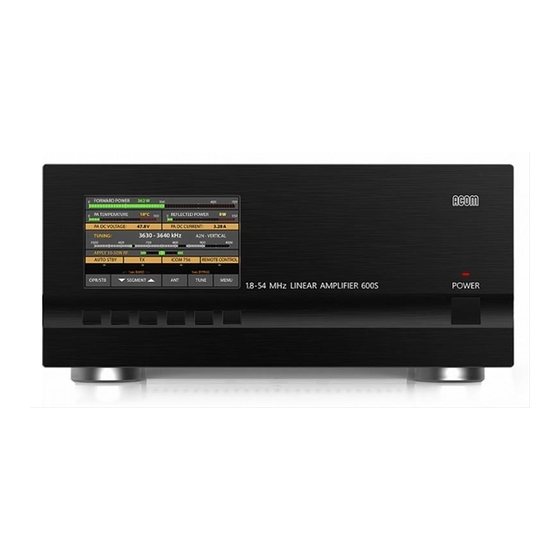
Fig. 3-1 Front panel During operation with the amplifier the display is illuminated and the red LED above the ON/OFF button indicates the button location which can be very useful in case of fast switching off in poor light conditions. c) Keyboard with 6 buttons for manual (local) control of the amplifier. - Page 12 Fig. 3-2 Basic screen b) Information area for measurements or alarm messages. Any two operator-chosen parameters will be normally displayed in this area on black background – see the list in S. 5-1 Measurements in the amplifier – AMP MEASURE. The alarm messages (either type WARNING or SOFT FAULT) appear with black font on yellow background on the area for measurements and are flashing frequently in order to attract the operator's attention (Fig.
-
Page 13: Control System - Buttons And Menus
3-5. Control system – buttons and menus The OPR/STB and the BAND (up and down) buttons are used for manual (local) control of the amplifier in the basic screen (Fig. 3-2): the left-most button – OPR/STB is for alternative switching of the amplifier mode between Operate and Stand-by;... - Page 14 SWR at the transceiver output are too high (over 5W or SWR over 2:1) immediately release the actuator and search for the reason as follows: check again whether the output control is set at minimum; check whether the frequency on which you are transmitting is within the operating range of the selected antenna;...
- Page 15 d) Check of the RX/TX switching and the amplifier idling current without RF power. Put the transceiver in such a regime that at pressed PTT or TX button a transmit request is applied to the amplifier but with no RF power on the transceiver output. For example, select SSB mode with microphone gain control reduced to zero or CW mode with Morse key up to avoid any RF power while requesting transmit mode to the amplifier by pressing the PTT or the TX button (do not use automatic CW keyer or VOX).
- Page 16 Enter menu MEASURE and check-up additionally: the drive power from the transceiver must be between 20 and 30W; PA BIAS must be between 2.5 and 2.9V (typically 2.8V); PA TEMPERATURE must be between the ambient and 80ºC (176ºF) depending on the power level and the duration of transmission.
-
Page 17: Operation With The Amplifier
the size, consider the frequency range in which the offered ferrites are effective – normally they are optimized for suppression of interferences on HF (with larger permeability), with medium permeability for HF-VHF or with low permeability - only the VHF range. The latter are ineffective for HF; whenever possible use shielded cables and ground their shields at both ends;... -
Page 18: Band Change, Standard And Expanded Frequency Coverage
N O T E Access to the Operate mode can be banned in the menu AMP SERVICE, the OPERATE ACCESS option (S. 5-2 and Fig. 5-2). The ban is universal. c) AUTO OPERATE option - can be activated or deactivated by the operator in the USER PREFERENCES menu –... -
Page 19: Change Of Antennas And Operation With An External Antenna Tuner
If the new frequency is out of the range admissible for the amplifier (S. 8-1(a)), the transmission request is denied and the following fault message appears on the screen: “FREQUENCY OUT OF RANGE” The standard frequency bands within which all amplifier parameters are guaranteed are listed in S. 8-1(a)). Extension or changes of the bands could be negotiated with the manufacturer. - Page 20 Fig. 4-1 – Appearance of an alarm message a) The first protection level is the WARNING type. Only a warning message appears on the screen accompanied by a sound signal, but without any physical reaction from the amplifier – Fig. 4-1. This occurs when some of the values monitored by the control unit approach too close the threshold of tripping the respective protection.
-
Page 21: Menus - Useful Instruments And Options
If it is not obvious due to what reason the protection has tripped, you can try to turn on the amplifier again. If the amplifier allows turning on after the fault, the display will be lit but instead of the basic screen, a fault message will appear with information about the reason for the latest automatic turning off (for example, overheating of the power supply unit or of the final stage and others). -
Page 22: Menu "Measurements In The Amplifier" - Amp Measure
5-1. Menu “Measurements in the amplifier” – AMP MEASURE The menu AMP MEASURE (Fig. 5-1) is accessible from the MENU SELECTION screen (Fig. 5) in all modes. It is possible to measure digitally 11 parameters in it, characterizing the amplifier operation and its regime. Fig. -
Page 23: Menu "Selection Of Cat/Aux Interface" - Cat/Aux Settings
(CD) and on the ACOM Internet page (S. 1-2). If your transceiver is not presented in the published list, it could still be connected with CAT/AUX to the ACOM 600S if its commands set and protocol are compatible with those proposed in the CAT/AUX SETTINGS menu. If needed, consult your dealer. -
Page 24: Menu "User Preferences
Fig. 5-3 Menu “Selection of CAT/AUX interface” – CAT/AUX SETTINGS At leaving the menu (by pressing the EXIT button), the parameters enclosed currently within square brackets remain selected (become effective). 5-4. Menu “USER PREFERENCES” Here the operator can adjust some secondary (minor) functions of the amplifier according to his personal preferences. -
Page 25: Reading The Faults Log
In order to select the user preference which has to be changed, first with the ITEM buttons (up and down) position the large colored window. Afterwards with the SELECT buttons (left or right) position the marker onto the desired value – Fig. 5-4. AUTOMATIC MENU EXIT. -
Page 26: Menu "Restore Default Settings
Fig. 5-5 Function FAULTS LOG Pressing the button FILE, the data can be downloaded in a plain text format through the built-in RS232 interface - see S. 7-4 for details. 5-6. Menu "RESTORE DEFAULT SETTINGS" The factory default settings for the user preferences and some other data can be reset here. While selecting the menu (Fig. -
Page 27: Remote Monitoring And Control
Fig. 5-6 Menu : RESTORE DEFAULT SETTINGS 6. REMOTE MONITORING AND CONTROL 6-1. General information Remote monitoring and control can be done with a computer connected to the RS232 interface of the amplifier. It can control and monitor the main amplifier functions as follows: activation (turn on) of the main power supply from the Low Energy (waiting) mode through simultaneous activation of the RTS and the DTR signals;... -
Page 28: Maintenance
W A R N I N G HIGH VOLTAGE! The mains line voltage plus a high DC voltage up to 500V inside the ACOM 600S amplifier are LETHAL! For your safety, pull the amplifier power plug out of the mains wall outlet and WAIT AT LEAST three minutes EACH TIME BEFORE servicing the amplifier! 7-1. -
Page 29: Simplified Schematic Diagram; Theory Of Operation
Simplified schematic diagram; theory of operation a) Power Amplifier Module. See Fig. 7-1 – ACOM 600S Simplified Schematic Diagram. The "heart" of the power amplifier module comprises two pieces of dual N-channel field-effect (LDMOS) transistors (Q101-Q101A and Q102-Q102A) type MRFE6VP6300H. The pair of transistors in each housing is paralleled, and the two housings operate in a push-pull configuration with a common grounded source. - Page 30 Fig. 7-1 ACOM 600S Simplified Schematic Diagram Page 29 of 33...
- Page 31 FSK/ATU (for control of external Automatic Antenna Tuner or Antenna Selector from ACOM – ready for a future development), Power Amplifier Module (PAM), and low-pass filters unit (LPF).
-
Page 32: Using The Fault Codes (Signatures) For Diagnostics
The data can be archived in a plain-text format through a computer using a standard program emulating a terminal (TTY). You can send the recorded file to your dealer or to ACOM accordingly. They could also provide the necessary instructions, if you choose to decode the downloaded hexadecimal data by yourself. -
Page 33: Firmware Updates
S. 5-5 for establishing the proper version. If you have any doubts about the versions, please consult your dealer before you undertake any action. When ACOM publishes a new version of the built-in firmware, the user can upload it in the amplifier after he checks their compatibility – see the note above. -
Page 34: Functions
14.5kg (32 Lbs). 9. DISCLAIMER of LIABILITY All ACOM 600S specifications and descriptions are based on the latest information available at the time of this document’s printing. As we always strive to constantly improve and update our products, ALL PRODUCT, PRODUCT SPECIFICATIONS AND DATA ARE SUBJECT TO CHANGE and ACOM... - Page 35 ACOM OOD Blvd. Nikola Mushanov 151 1330 Sofia, Bulgaria phone: +359 2 920 96 55 fax: +359 2 920 96 56 e-mail: acom@acom-bg.com acom@mail.orbitel.bg www.acom-bg.com...
Need help?
Do you have a question about the 600S and is the answer not in the manual?
Questions and answers