Table of Contents
Advertisement
Advertisement
Table of Contents

Related Manuals for Acom 2000R


Summary of Contents for Acom 2000R
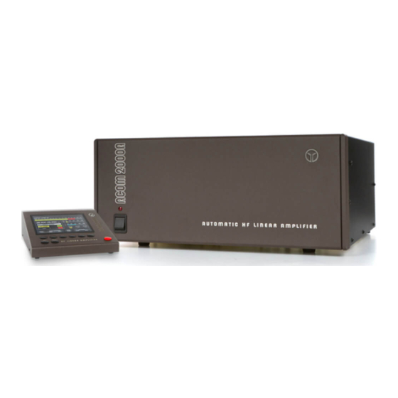
- Page 1 AUTOMATIC HF LINEAR AMPLIFIER OPERATING MANUAL...
-
Page 2: Table Of Contents
Table of Contents 1. GENERAL INFORMATION ........3 1-1. - Page 3 5-5. CLR ............22 5-6.
-
Page 4: General Information
If assistance is needed, you should contact your local dealer first. If you still have an issue you need to discuss with one of ACOM's specialists. The contact information is as follows: fax: (+ 359 2) 920 96 56, e-mail acom@mail.orbitel.bg, acom@aster.net or by mail: blvd.”Nikola Mushanov”-151, 1330 Sofia, Bulgaria. -
Page 5: Safety Considerations, Explicit Definitions
Uses two 4CX800A (GU74B) Svetlana high performance ceramic-metal tetrodes with plate dissipation of 800W each (forced air cooling, grid-driven). ACOM maintains strict adherence to the tube manufacturer’s specifications for cooling and for the sequence of applying and removing the different tube voltages. Starting filament current is limited, and there is constant monitoring and protection of all supply voltages and currents. - Page 6 and electromagnetic compatibility requirements, as well as FCC regulations. This operating manual contains information, precautions, indications for cautions and warnings which must be followed by the user to ensure safe operation and to keep the ACOM2000A in safe operating condition. PRECAUTIONS: The EXPLICIT DEFINITIONS described below apply to this operating manual: W A R N I N G notes call attention to a procedure which, if not correctly performed, could result in...
-
Page 7: Installation
2. INSTALLATION 2-1. Unpacking and Initial Inspection N O T E Before you start any action on installing the amplifier, thoroughly read through this manual. First carefully inspect both cardboard cartons and their contents for physical damage. If damage is noticed, notify your dealer immediately. Delay may infringe carrier's warranty conditions. -
Page 8: Transformer Installation
Normally the amplifier is supplied with Voltage Selector set for a nominal mains voltage of 240V. There might be exceptions in cases of special delivery and then the voltage set is noted in the Table of Individual Data (Table 2-1). If your mains has a different nominal voltage, it will be necessary for you to contact your dealer or see the TECHNICAL SUPPLEMENT for details. -
Page 9: Connections
Move the transformer, using its rope sling handle, into the compartment. Take care not to damage the wiring or components and position the transformer so that the captive nuts are aligned with the corresponding chassis holes. Make sure that the transformer is centered. The transformer bolts must be installed NOW for safe operation. - Page 10 a) First connect the ground stud of the amplifier (on the rear panel, marked GND) to the station's grounding system (Fig.2-2). b) Connect a coaxial cable with a PL-259 plug from the transceiver output to the amplifier rear panel RF INPUT socket.
-
Page 11: Installation Of Optional Fan
C A U T I O N Do not connect to the connector, marked INTERFACE a "standard" cable because this may result in damage in both - amplifier or connected equipment. In order to use PC, a special cable must be prepared. Contact your dealer or see TECHNICAL SUPPLEMENT for details. -
Page 12: Power On, Rcu Controls, Indicators And Menus
3. POWER ON, RCU CONTROLS, INDICATORS AND MENUS C A U T I O N Before you turn the amplifier on, at least 2 hours should have expired since it was brought in and unpacked in the room where it will be used. Pay particular attention when you move it from a very cold into a very warm place - condensation is likely and this could result in damage to the high voltage circuits. - Page 13 In this position only the RCU is operational, while the amplifier itself is still turned off. The control of the amplifier is structured in two menus - OFF and MAIN, each having several sub-menus : POWER ON OFF MENU MAIN MENU S.4-1 INFO sub-menu S.5-1...
-
Page 14: Main Menu, Frequency And Antenna Selection
INFO sub-menu is shown between square brackets in the illustration above. If you wish to select another sub-menu, move the brackets in the required direction with the (UP), (DOWN), (LEFT), and (RIGHT) arrows, so that they enclose the desired item. Press (Enter) to open the respective sub-menu. - Page 15 N O T E When you intend to have a pause in operating, it is better to leave the amplifier in STBY mode instead of turning it off, using the red colored button. Tube life is shortened by repeatedly turning on and off the tube heater supply. N O T E However, if you unintentionally power-off the amplifier, it is best to switch it on again immediately.
- Page 16 In the example, a signal frequency between 3650 and 3700kHz was applied and antenna No 3 was last used there with tuning done by the user (USR). NOTE If in DEF sub-menu (see S.5-6) AUTO ANTENNA CHANGE is OFF , then the antenna number would not change with frequency and remains No 1.
-
Page 17: Auto Tune Sub-Menu
4-1. AUTO TUNE sub-menu a) Let us examine the difference between the two types: DEF- and USR- tunings. DEFault tuning settings are permanently available in your amplifier memory. They are normally used when the load VSWR at the input end of the feed line is very low. Real loads often have VSWR greater than 1.5:1, which usually requires the use of an outboard antenna tuner. - Page 18 b) Procedure for preparation of USR-tunings. We recommend that you prepare USR-tunings for the center frequencies of the segments, but you can do them for other preferred frequencies. N O T E If you use more than one antenna per segment, it is necessary that you select the proper antenna number (see S.4d) BEFORE the next step.
-
Page 19: Manual Tune Sub-Menu
4-2. MANUAL TUNE sub-menu C A U T I O N During manual tune do not apply continuous drive longer than 3 minutes and after that leave pauses of 1-2 minutes for cooling of the tubes. If for some reason you prefer to match the antenna impedance manually, you can do it in the MAN.TUNE sub-menu. -
Page 20: Service Sub-Menu
For example, for TEMP-F: During measuring, the amplifier can be used and controlled in OPR or STBY modes, to transmit and change the frequency segment and antenna if a new frequency is applied to it. Return to the MAIN - menu is done by the button. -
Page 21: Erasing Usr Segments (Return To Def- Tunings)
4-5. Erasing USR segments (return to DEF- tunings) If you wish to clear a USR setting for a frequency segment and/or antenna, there are two ways this can be accomplished: a) to clear all memorized USR-tuning settings - the procedure is described in S.5-5. b) for separate segments and/or antennas: select the segment and antenna for which you want to erase the USR-tuning (see S.4c,d). -
Page 22: Info (Info Box)
5-3. INFO (INFO BOX) During operation of the amplifier, information is stored in the nonvolatile memory about the 12 most recent protection trips or irregularities and the time when they have occurred (indicated as tubes working hours). This information, along with other service data is also stored which can be transmitted to the service center for use by remote diagnostics. -
Page 23: Clr
5-5. CLR N O T E If you use this function, it is advisable that you update the USR tunings (see S.4-1). This function clears all USR-tunings from the nonvolatile memory but does not change anything else in the INFO-BOX. The function is activated by pressing the button after having selected the CLR sub-menu. -
Page 24: Erasing Nonvolatile Memory
c) AUTO ANTENNA CHANGE Selection is changed by means of the buttons. When "ON" is selected, while changing frequency segments (manually or following the transceiver frequency - see S.4c), the antenna last used in the respective segment and tuning settings for it will be selected. This is convenient when your antennas are not more than 1 or 2 for each band, because otherwise, while changing the frequency segment, you have to keep track of which antenna you used last. -
Page 25: Maintenance
The procedure is now completed and the amplifier remains in OFF-menu with no user data in it. The serial numbers of the RCU, amplifier and its tubes as well as the firmware revision code and DEFault tuning settings, however, are preserved. N O T E After this procedure set new data in OFF-menu (DEF, LOCK and CALL sub-menus) and update the USR-tunings for the frequency segments and antennas to be used... -
Page 26: Fuses Replacement
6-3. Fuses Replacement If occasion should require replacement of the mains fuses, use only standard ones. The two Primary Mains Fuses of the amplifier are located on the rear panel (Fig. 2.2). They are 20A/250V Quick blow, 1-1/4 x 1/4 inch Cartridge Fuses, Size "0" Ceramic. Besides the primary fuses, on the MAINS CONTROL BOARD there are six small glass fuses (5x20mm) which are not replaced by the user. -
Page 27: Troubleshooting
All voltages delivered from the LOW VOLTAGE and HIGH VOLTAGE SUPPLY PCBs, tubes currents, temperatures and airflow cooling capability are permanently monitored. A lot of software-derived protections are based on this information. The SIGNAL FILTER PCB and RFC1 eliminate RF feedback from incoming cables, including the mains power cord. - Page 28 DRIVE FREQUENCY OUT OF RANGE check the transceiver frequency; OFF5* DRIVE POWER TOO HIGH RD&T* EXCESSIVE G2 CURRENT RD&T* EXCESSIVE PLATE CURRENT RD&T* FREQUENCY VIOLATION submit to your dealer your license for opera- tion in the respective frequency band. FRONT TUBE EXHAUST TEMP TOO HIGH check if air intake (rear panel) and exhaust (above tubes) openings are clear of obstruc- tions;...
- Page 29 LOW BATTERY DATA IS IN DANGER see S.6-2. LOW AIRFLOW check if air intake (rear panel) and exhaust (above tubes) openings are clear of obstruc- tions; RD&T* LOW GAIN RD&T*; check the coaxial cable from trans- ceiver output to amplifier input. MICROPROCESSOR CONFLICT OFF5* MOTOR VOLTAGE TOO HIGH...
-
Page 30: Specifications
7. SPECIFICATIONS 7-1. Parameters a) Frequency Coverage: All amateur bands 1.8-29.7MHz; extensions and/or changes on request. b) Power Output: 1500W PEP or continuous carrier, no mode limit. In continuous carrier modes (RTTY etc.) for transmissions longer than 15 minutes (up to several hours depending on ambient temperature), the optional auxiliary fan must be mounted. -
Page 31: Functions
7-2. Functions a) Antenna Impedance Matching Process: automated. b) Provides Antenna Control Interface for Automatic Antenna Selector and Tuner. c) User tuning settings memory - nonvolatile for up to 10 antennas per frequency segment (settings for 50 Ohm default provided). On power-up, the lithium backup battery voltage is checked. The battery is rechecked every 24 hours that amplifier remains powered up for maximum data security. -
Page 32: Storage And Shipment
j) Measurement and/or constantly monitoring of 20 most important parameters of the amplifier via RCU and/or PC. k) Adjustable RCU Beep and Contrast. 7-3. Storage and Shipment C A U T I O N Should you need to transport the amplifier, use the original packing as described below. -
Page 33: Brief Menu Guide
8. BRIEF MENU GUIDE POWER SWITCH -> OFF MENU: HELP - to read serial numbers, power-on hours, suggestions CALL - to change inscription in OFF-menu INFO - to send telephone diagnostics information LOCK - to set or change access code CLR - to delete all USR-tunings DEF - to define mains voltage diversions, network self address and antenna change mode ON/OFF BUTTON ->...
Need help?
Do you have a question about the 2000R and is the answer not in the manual?
Questions and answers