Table of Contents
Advertisement
Statement:
This manual is the intellectual property of Foxconn Inc. Although the
information in this manual may be changed or modified at any time,
Foxconn does not obligate itself to inform the user of these changes.
Trademark:
All trademarks are the property of their respective owners.
Version:
User's Manual V1.1 in English for NF4K8MC/NF4XK8MC series motherboard.
P/N: 91-181-NF4-KX-1E
Symbol description:
Note: refers to important information that can help you to use motherboard
better.
Attention: indicates that it may damage hardware or cause data loss,
and tells you how to avoid such problems.
Warning: means that a potential risk of property damage or physical
injury exists.
More information:
If you want more information about our products, please visit the following
website: http://www.foxconnchannel.com
1
2005-4-18, 15:13
Advertisement
Table of Contents

Related Manuals for Foxconn NF4K8MC


Summary of Contents for Foxconn NF4K8MC
-
Page 1: More Information
This manual is the intellectual property of Foxconn Inc. Although the information in this manual may be changed or modified at any time, Foxconn does not obligate itself to inform the user of these changes. Trademark: All trademarks are the property of their respective owners. -
Page 2: Declaration Of Conformity
Declaration of conformity HON HAI PRECISION INDUSTRY COMPANY LTD 66 , CHUNG SHAN RD., TU-CHENG INDUSTRIAL DISTRICT, TAIPEI HSIEN, TAIWAN, R.O.C. declares that the product Motherboard NF4K8MC/NF4XK8MC is in conformity with (reference to the specification under which conformity is declared in accordance with 89/336 EEC-EMC Directive) EN 55022/A1: 2000 Limits and methods of measurements of radio disturbance... - Page 3 Declaration of conformity Supplementary Information: This device complies with Part 15 of the FCC Rules. Operation is subject to the following two conditions : (1) this device may not cause harmful interference, and (2) this device must accept any interference received, including interference that may cause undesired operation.
-
Page 4: Table Of Contents
Table of Contents Chapter Product Introduction Main Features ....................2 Motherboard Layout ..................4 Chapter Installation Instructions CPU ......................7 Memory ....................... 11 Power Supply .................... 13 Rear Panel Connectors ................14 Other Connectors ..................16 Expansion Slots ..................20 Jumpers ..................... - Page 5 Table of Contents Chapter Driver CD Introduction Utility CD content ..................Start to install drivers ................. Chapter NVIDIA RAID Introduction NVIDIA RAID ..................... 2005-4-18, 15:13...
- Page 6 Warning: 1. Attach the CPU and heatsink using silica gel to ensure full contact. 2. It is suggested to select high-quality, certified fans in order to avoid damage to the motherboard and CPU due to high temperature. 3. Never turn on the machine if the CPU fan is not properly installed. 4.
- Page 7 This manual is suitable for motherboard of NF4K8MC/ NF4XK8MC series. Each motherboard is carefully designed for the PC user who wants diverse features. with onboard 10M/100M LAN with onboard 1Giga LAN with 6-channel audio with 8-channel audio with 1394 function with SATA function with RAID function You can find PPID label on the motherboard.
- Page 8 Chapter Thank you for buying WinFast NF4K8MC/NF4XK8MC series motherboard. This series of motherboard is one of our new products, and offers superior performance, reliability and quality, at a reasonable price. This motherboard adopts the advanced nForce 4 chipset, providing users a computer plat- form with a high integration-compatibility-performance price ratio.
-
Page 9: Chapter Product Introduction
Chapter 1 Product Introduction Main Features Size: mATX form factor of 9.6” x 9.6” Microprocessor: Supports Socket-939 for AMD Athlon processors Athlon 64 FX Supports HyperTransport technology Chipset: NVIDIA chipset: nForce 4 System Memory Two 184-pin DDR DIMM slots Supports DDR 266/333/400 memory Supports 128/256/512/1024Mb technology up to 2GB USB 2.0 Port Supports hot-plug... - Page 10 Chapter 1 Product Introduction Onboard LAN(-L/-K) (optional) Supports10/100/1000(-L/-K)Mbps Ethernet LAN interface built-in on board Onboard Audio AC’ 97 2.3 Specification Compliant Supports S/PDIF output Onboard Line-in jack, Microphone jack, Line-out jack Supports 6-channel audio (setting via software) BIOS Licensed advanced AWARD (Phoenix) BIOS, supports flash ROM, Plug-and- Play Supports HDD, Floppy, CD-ROM, SCSI HDD or USB device boot up Green Function...
-
Page 11: Motherboard Layout
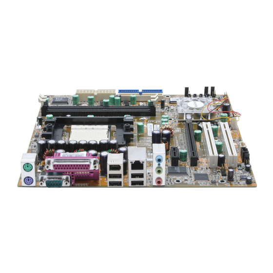
Chapter 1 Product Introduction Motherboard Layout 15.COM2 Connector 2.Front Audio Connector 16.Boot Block Jumper 3.CD_IN Connector 17.SATA Connectors 4.AUX_IN Connector 18.ATA 133/100/66/33 IDE Connectors 5.SPDIF_OUT Connector 19.FDD Connector 6.Speaker Connector 20.IrDA Connector 7.PCI Expansion Slots 21.24-pin ATX Power Connector 8.Chipset Fan Connector 22.184-pin DIMM Slots 9.Chipset: NVIDIA nForce4 23.CPU_FAN Connector... - Page 12 Chapter 1 Product Introduction Chapter This chapter introduces the hardware installation process, including the installation of the CPU and memory. It also addresses the connection of your power supply, use of the rear panel connectors, connection of hard drive and floppy drive data cables, and setting up various other feature of the motherboard.
- Page 13 Chapter 2 Installation Instructions Take note of the following precautions before you install components or change settings. 1. Use a grounded wrist strap or touch a safely grounded object, such as an attached power supply, before handling components to avoid damaging them due to static electricity.
-
Page 14: Chapter Installation Instructions Cpu
Chapter 2 Installation Instructions This motherboard supports Athlon 64, Athlon 64FX family processors with HyperTransport Technology. Attention: The CPU pins must be properly aligned with the holes in the socket, otherwise the CPU may be damaged. Installation of CPU Follow these steps to install the CPU. 1. - Page 15 Chapter 2 Installation Instructions Installation of CPU Fan New technology allows processors to run at higher and higher frequencies. To avoid problems arising from high-speed operation, for example, overheating, you need to install the proper fan. The following procedure is provided for reference only, please refer to your CPU fan user guide for the actual procedure.
- Page 16 Chapter 2 Installation Instructions 3. Place the cooling set onto the re- 4. Align the other end of the reten- tention mechanism. Attach one end tion bracket to fasten the cooling of the retention bracket to retention set on the top of the retention mechanism.
- Page 17 Chapter 2 Installation Instructions CPU Qualified Vendor List The following table lists the CPUs that have been tested and qualified for use with this motherboard. Vendor Description Athlon 64 3500+ Athlon 64 3800+ Athlon 64 4000+ Athlon 64 FX-55 Athlon 64 FX-53...
-
Page 18: Memory
Chapter 2 Installation Instructions Memory This motherboard includes two 184-pin slots with 266/333/400 MHz Dual Chan- nel DDR DRAM interface, You must install at least one memory module to ensure normal operation and install to DIMM1 at first. If you install two modules, they must be the same speed. - Page 19 Chapter 2 Installation Instructions Memory Qualified Vendor List The following table list is the memory modules that have been tested and qualified for use with this motherboard. Vendor Size Type CORSAIR DDR466 256MB CORSAIR DDR500 256MB CORSAIR DDR400 512MB DDR500 256MB DDR266 256MB...
-
Page 20: Power Supply
Chapter 2 Installation Instructions Power Supply This motherboard uses an ATX power supply. In order to avoid damaging any devices, make sure that they have been installed properly prior to connecting the power supply. 24-pin ATX Power Connector 24-pin ATX Power Connector: PWR1 PWR1 is the ATX power supply connector. -
Page 21: Rear Panel Connectors
Chapter 2 Installation Instructions Rear Panel Connectors This motherboard provides the following ports as below: Parallel Port 1394 Port LAN Port (optional) (optional) (Printer Port) Line-in jack PS/2 Mouse Connector Line-out jack PS/2 Keyboard Microphone Connector jack Serial Port USB 2.0 Ports (COM1) PS/2 Mouse Connector This green 6-pin connector is for a PS/2 mouse. - Page 22 Chapter 2 Installation Instructions Line-in Line-out Microphone When using a 6-channel sound source, connect the front speaker to the green audio output; connect the surround sound speaker to the blue audio output; connect the center speaker/subwoofer to the red Microphone output, as shown in the following figure: Blue Green...
-
Page 23: Other Connectors
Chapter 2 Installation Instructions Other Connectors This motherboard includes connectors for FDD, IDE devices, SATA devices, USB devices, IR module, CPU fan, system fan, and others. Floppy Connector: FLOPPY This motherboard includes a standard floppy connector, supporting 360 K, 720 K, 1.2 M, 1.44 M, and 2.88 M FDDs. - Page 24 Chapter 2 Installation Instructions Power LED Connector (PLED) Attach the connector to the Power LED on the front panel of the case. The Power LED indicates the power supply status. When the system is in S0 status, the LED is on. When the system is in S1 status, the LED is blinking. When the system is in S3, S4, S5 staus, the LED is off.
- Page 25 Chapter 2 Installation Instructions S-ATA Connectors: SATA0, SATA1, SATA2, SATA3 (optional) The Serial ATA connectors are used to connect the Serial ATA devices to the motherboard. These con- nectors support the thin Serial ATA cables for pri- mary internal storage devices. The current Serial ATA interface allows up to 150MB/s data transfer SATA0/1/2/3 rate.
- Page 26 Chapter 2 Installation Instructions S/PDIF Out Connector: SPDIF_O1 The S/PDIF out connector is capable of providing 3.3V SPDIF OUT digital audio to external speaker or compressed AC3 data to an external Dolby digital decoder. SPDIF_O1 COM2 Connector: COM2 (optional) SOUT This connector accommodates a second serial port RLSD using an optional serial port bracket.
-
Page 27: Expansion Slots
Chapter 2 Installation Instructions Expansion Slots This motherboard includes two 32-bit Master PCI bus slots and one PCI Ex- press x1 slot, and one PCI Express x16 slot. PCI Slots The expansion cards can be installed in the two PCI slots. When you install or remove such cards, please make sure that the power cord has been unplugged from the power supply. - Page 28 Chapter 2 Installation Instructions Installing an expansion card 1. Before installing the expansion card, read the documentation that came with it and make the necessary hardware settings for the card. 2. Make sure to unplug the power cord before adding or removing expansion cards.
-
Page 29: Jumpers
Chapter 2 Installation Instructions Jumpers Users can change the jumper settings on this motherboard if necessary. This section explains how to use the various functions of this motherboard by chang- ing the jumper settings. Users should read the following contents carefully prior to modifying any jumper settings. - Page 30 Chapter 2 Installation Instructions BIOS Writer-Protection Jumper: JWP1 If the jumper JWP1 is set as enable (pin 2 & pin 3), the system BIOS is protected from being attacked EN WP by a serious virus, such as the CIH virus. You will be unable to flash the BIOS to the motherboard Normal when the system BIOS is protected.
- Page 31 Chapter 2 Installation Instructions Starting up for the first time 1. After making all the connections, replace the system case cover. 2. Make sure that all switches are turned off. 3. Turn on the devices in the following order. Monitor External SCSI devices (starting with the last device on the chain) System power 4.
- Page 32 Chapter This chapter tells how to change system settings through the BIOS Setup menus. Detailed descriptions of the BIOS param- eters are also provided. You have to run the Setup Program when the following cases occur: 1. An error message appears on the screen during the system POST process.
-
Page 33: Chapter Bios Description
Chapter 3 BIOS Description Enter BIOS Setup The BIOS is the communication bridge between hardware and software, correctly setting up the BIOS parameters is critical to maintain optimal system performance. Power on the computer, when the following message briefly appears at the bottom of the screen during the POST (Power On Self Test), press the <Del>... - Page 34 Chapter 3 BIOS Description Advanced BIOS Features The advanced system features can be set up through this menu. Advanced Chipset Features The values for the chipset can be changed through this menu, and the sys- tem performance can be optimized. Integrated Peripherals All onboard peripherals can be set up through this menu.
-
Page 35: Standard Cmos Features
Chapter 3 BIOS Description Standard CMOS Features This sub-menu is used to set up the standard CMOS features, such as the date, time, HDD model and so on. Use the arrow keys select the item to set up, and then use the <PgUp> or <PgDn> key to choose the setting values. Standard CMOS Features Menu Date This option allows you to set the desired date (usually as the current date) with... - Page 36 Chapter 3 BIOS Description Award (Phoenix) BIOS can support 4 HDD modes: CHS, LBA and Large or Auto mode. For HDD<528MB For HDD>528MB & supporting LBA (Logical Block Addressing) Large For HDD>528MB but not supporting LBA Auto Recommended mode Drive A/B (optional) This option allows you to select the kind of FDD to be installed, including [None], [360K, 5.25in], [1.2M, 5.25in], [720K, 3.5in], [1.44M, 3.5in] and [2.88 M, 3.5in].
- Page 37 Chapter 3 BIOS Description Memory This is a Displays-Only Category, determined by POST (Power On Self Test) of the BIOS. Base Memory The BIOS POST will determine the amount of base (or conventional) memory installed in the system. Extended Memory The BIOS determines how much extended memory is present during the POST.
-
Page 38: Bios Feature
Chapter 3 BIOS Description BIOS Feature BIOS Feature Menu [SuperBoot] SuperBoot (Default: Disabled) SuperBoot allows system-relevant information to be stored in CMOS upon the first normal start-up of your PC, and the relevant parameters will be restored to help the system start up more quickly on each subsequent start-up. The available setting values are: Disabled and Enabled. -
Page 39: Advanced Bios Features
Chapter 3 BIOS Description Advanced BIOS Features Advanced BIOS Features Menu Removable Device Priority This option is used to select the priority for removable device start-up. After pressing <Enter>, you can select the removable device using the <PageUp>/ <PageDn> or Up/Down arrow keys, and change the removable device priority using <+>... - Page 40 Chapter 3 BIOS Description Boot Other Device (Default: Enabled) With this function set to Enabled, the system will boot from some other devices if the first/second/third boot devices failed. The available setting val- ues are: Disabled and Enabled. Security Option (Default: Setup) When it is set to Setup, a password is required to enter the CMOS Setup screen;...
-
Page 41: Advanced Chipset Features
Chapter 3 BIOS Description Advanced Chipset Features Advanced Chipset Features Menu DRAM Configuration (Default: Press Enter) Press <Enter> to set the items about DRAM Configuration. Please refer to page 35. CPU Spread Spectrum (Default: Center Spread) If you enable CPU spread spectrum, it can significantly reduce the EMI (Electro- Magnetic Interference) generated by the system. - Page 42 Chapter 3 BIOS Description Max Memclock (MHz) (Default: Auto) User can place an artificial memory clock limit on the system. Memory is pre- vented from running faster than this frequency. 1T/2T Memory Timing (Default: Auto) This setting controls the SDRAM command rate. Selecting [Auto] allows SDRAM signal controller to run at 1T (T=clock cycles) rate.
-
Page 43: Integrated Peripherals
Chapter 3 BIOS Description Integrated Peripherals Integrated Peripherals Menu IDE Function Setup Press <Enter> to set the items about IDE function. Please refer to page 37. RAID Config Press <Enter> to set the items of RAID configuration function. Please refer to page 38. - Page 44 Chapter 3 BIOS Description IDE Function Setup Menu Primary/Secondary Master/Slave PIO (Default: Auto) The four IDE PIO (Programmed Input/Output) fields let you set a PIO mode (0-4) for each of the four IDE devices that the onboard IDE interface supports. Modes 0 through 4 provide successively increased performance.
- Page 45 Chapter 3 BIOS Description RAID Config Menu RAID Enable (Default: Disabled) This option is used to disable or enable the RAID function. When enabled, the following grayed items will be activated. IDE Primary/Secondary Master/Slave RAID (Default: Disabled) This feature allows users to enable or disable the RAID function for each IDE hard disk drive.
-
Page 46: Power Management Setup
Chapter 3 BIOS Description Power Management Setup Power Management Setup Menu ACPI function (Default: Enabled) ACPI stands for “Advanced Configuration and Power Interface”. ACPI is a standard that defines power and configuration management interfaces be- tween an operating system and the BIOS. In other words, it is a standard that describes how computer components work together to manage system hardware. - Page 47 Chapter 3 BIOS Description WOR (RI#) From Soft-Off (Default: Disabled) If this option is enabled, it allows the system to resume from a software power down or power saving mode whenever there is an incoming call to an in- stalled fax/modem. This function needs to be supported by the relevant hard- ware and software.
-
Page 48: Pnp/Pci Configurations
Chapter 3 BIOS Description PnP/PCI Configurations PnP/PCI Configurations Menu Init Display First (Default: PCI Slot) This option is used to set which display device will be used first when your PC starts up. The available setting values are: PCI Slot, PCIEx. Reset Configuration Data (Default: Disabled) This option is used to set whether the system is permitted to automatically distribute IRQ DMA and I/O addresses each time the machine is turned on. -
Page 49: Pc Health Status
Chapter 3 BIOS Description PC Health Status Shutdown Temperature (Default: 90 C/194 This option is used to set the system temperature upper limit. When the temperature exceeds the setting value, the motherboard will automatically cut off power to the computer. The available setting values are: 80 C/176 C/185 F, 90... -
Page 50: Load Fail-Safe Defaults
Chapter 3 BIOS Description Load Fail-Safe Defaults Select this option and press <Enter>, it will pop up a dialogue box to allow you to install fail-safe defaults for all appropriate items in the Setup Utility. Select <Y> and press <Enter> to load the defaults. Select <N> and press <Enter> to not load. -
Page 51: Save & Exit Setup
Chapter 3 BIOS Description Under the menu “Advanced BIOS Features Setup”, if you select “System” in Security Option, the screen will prompt you to enter password once the system is started or you want to enter CMOS setting program. If the password is wrong, it will refuse you to continue. - Page 52 Chapter The utility CD that came with the motherboard contains useful software and several utility drivers that enhance the mother- board features. This chapter includes the following information: Utility CD content Start to install drivers...
- Page 53 Chapter 4 Utility CD content This motherboard comes with one Utility CD. To begin using the CD, simply insert the CD into your CD-ROM driver . The CD w i l l automatically display the main menu screen.
- Page 54 Chapter 4 Select <Install Driver> to enter the driver installation menu (as following picture). Click the relevant button to install nVIDIA nForce Chipset System, DirectX 9.0b.
- Page 55 Chapter 5 NVIDIA RAID Introduction Chapter NVIDIA brings Redundant Array of Independent Disks (RAID) technology—which is used by the world’s leading businesses—to the common PC desktop. This technol- ogy uses multiple drivers to either increase total disk space or to offer data protection. This chapter includes the following information: Basic Configuration Setting up BIOS...
-
Page 56: Nvidia Raid
Chapter 5 NVIDIA RAID Introduction NVIDIA RAID RAID Arrays This section describes the following types of RAID arrays that NVIDIA RAID supports: • RAID 0 RAID 0 defines a disk striping scheme that improves the disk read and write times for many applications. •... -
Page 57: Basic Configuration Instructions
Chapter 5 NVIDIA RAID Introduction Basic Configuration Instructions The following are the basic steps for configuring NVIDIA RAID: Non-Bootable RAID Array 1. Choose the hard disks that are to be RAID enabled in the system BIOS. 2. Specify the RAID level, either Mirroring (RAID 1), Striping (RAID 0), Stripe Mirroring (RAID 0+1), or Spanning (JBOD) and create the desired RAID array. -
Page 58: Setting Up The Bios
Chapter 5 NVIDIA RAID Introduction Setting Up the BIOS 1. Start up the computer, then press <Delete> to enter the BIOS setup. Use the arrow keys to select Integrated Peripherals, then press <Enter>. 2. Use the arrow keys to highlight the RAID Config, then press <Enter>. 3. -
Page 59: Entering The Raid Bios Setup
Chapter 5 NVIDIA RAID Introduction Entering the RAID BIOS Setup 1. After rebooting your PC, wait until you see the RAID software prompting you to press <F10>. The RAID prompt appears as part of the system POST and boot process prior to loading OS. 2. - Page 60 Chapter 5 NVIDIA RAID Introduction In the example above, 1.0.M means the hard drive is attached to Adapter 1, Channel 0, and the drive is set to Master. The following is a list of all possible combinations: Parallel ATA 0.0.M Adapter 0, Channel 0, Master 0.0.S Adapter 0, Channel 0, Slave...
- Page 61 Chapter 5 NVIDIA RAID Introduction To designate a free disk to be used as a RAID array disk, 1. Tab to the Free Disks section. The first disk in the list is selected. 2. Move it from the Free Disks block to the Array Disks block by pressing the right arrow key ( ).
- Page 62 Chapter 5 NVIDIA RAID Introduction 2. Press <Y> if you want to wipe out all the data from the RAID array, otherwise press <N>. You must choose Yes if the drives were previously used as RAID drives. The Array List window appears, where you can review the RAID arrays that you have set up.
-
Page 63: Nvidia Raid Utility Installation
Chapter 5 NVIDIA RAID Introduction NVIDIA RAID Utility Installation Installing the NVIDIA RAID Software Under Windows (for Non-bootable RAID Array) This section describes how to run the setup application and install the RAID software which will upgrade the Windows IDE driver and install the RAID driver. 1. - Page 64 Chapter 5 NVIDIA RAID Introduction Installing the RAID Driver (for bootable RAID Array) 1. After you complete the RAID BIOS setup, boot from the Windows CD, and the Windows Setup program starts. 2. Press <F6> and wait for the Windows Setup screen to appear. 3.
- Page 65 Chapter 5 NVIDIA RAID Introduction 4. Press <Enter> to continue with operating system installation. Be sure that copying files from the floppy is completed, then take out the floppy. 5. Follow the instructions on how to install operating system. During the GUI portion of the install you might be prompted to click Yes to install the RAID driver.
- Page 66 Chapter 5 NVIDIA RAID Introduction Initializing and Using the Disk Array The RAID array is now ready to be initialized under Windows. 1. Launch Computer Management by clicking “Start” —> “Settings” —> “Control Panel”, then open the “Administrative Tools” folder and double click on “Com- puter Management”.
-
Page 67: Win2K Limitation With Bootable Raid
Chapter 5 NVIDIA RAID Introduction Win2K Limitation with Bootable RAID In Windows 2000 (Service Pack 2 or previous versions), the end user cannot install this operating system to a bootable RAID volume. Solution There are two solutions to resolve this issue. I) Use the NVRAID Tool (nForce Driver Version 5.xx) to convert the boot volume to a RAID array. - Page 68 Chapter 5 NVIDIA RAID Introduction 13. Select Convert Array under the System Tasks. The Convert Array wizard is displayed. Then select Next. 14. Select the desired type of RAID array you want to convert. Then select Next. 15. You are prompted to select the desired Free Disk(s) to add to the bootable RAID array.
Need help?
Do you have a question about the NF4K8MC and is the answer not in the manual?
Questions and answers