Table of Contents
Advertisement
Statement:
This manual is the intellectual property of Foxconn, Inc. Although the
information in this manual may be changed or modified at any time,
Foxconn does not obligate itself to inform the user of these changes.
Trademark:
All trademarks are the property of their respective owners.
Version:
User's Manual V1.0 for 945GZ7MC motherboard.
Symbol description:
Note: refers to important information that can help you to use motherboard
better.
Attention: indicates that it may damage hardware or cause data loss,
and tells you how to avoid such problems.
Warning: means that a potential risk of property damage or physical
injury exists.
More information:
If you want more information about our products, please visit Foxconn's
website: http://www.foxconnchannel.com
WEEE: The use of the symbol indicates that this product may not be treated
as household waste. By Ensuring this product is disposed of correctly, you will
help prevent potential negative consequences for the environment and human
health, which could otherwise be cause by inappropriate waste handling of this
product. For more detailed information about recycling of this product, please
contact your local city office, your household waste disposal service or the shop
where you purchased the product.
Advertisement
Table of Contents

Related Manuals for Foxconn 945GZ7MC


Summary of Contents for Foxconn 945GZ7MC
-
Page 1: More Information
This manual is the intellectual property of Foxconn, Inc. Although the information in this manual may be changed or modified at any time, Foxconn does not obligate itself to inform the user of these changes. Trademark: All trademarks are the property of their respective owners. -
Page 2: Declaration Of Conformity
HON HAI PRECISION INDUSTRY COMPANY LTD 66 , CHUNG SHAN RD., TU-CHENG INDUSTRIAL DISTRICT, TAIPEI HSIEN, TAIWAN, R.O.C. declares that the product Motherboard 945GZ7MC is in conformity with (reference to the specification under which conformity is declared in accordance with 89/336 EEC-EMC Directive) þ... - Page 3 Declaration of conformity FOXCONN Trade Name: Model Name: 945GZ7MC Industry Inc. Responsible Party: Address: 458 E. Lambert Rd. Fullerton, CA 92835 Telephone: 714-738-8868 Facsimile: 714-738-8838 Equipment Classification: FCC Class B Subassembly Type of Product: Motherboard Manufacturer: HON HAI PRECISION INDUSTRY...
-
Page 4: Table Of Contents
Table of Contents Chapter Product Introduction Main Features ..................... 2 Layout ......................3 Rear I/O Ports ..................... 4 Chapter Installation Instructions C PU ......................6 Memory ...................... 9 Power Supply ................... 10 Other Connectors ..................11 Expansion Slots ..................13 Jumpers .................... - Page 5 Attention: 1. Attach the CPU and heatsink using silica gel to ensure full contact. 2. It is suggested to select high-quality, certified fans in order to avoid damage to the motherboard and CPU due high temperatures. 3. Never turn on the machine if the CPU fan is not properly installed. 4.
- Page 6 This manual is suitable for motherboard of 945GZ7MC. Each motherboard is carefully designed for the PC user who wants diverse features. -6 with 6-Channel audio (Default is omitted) -8 with 8-Channel audio -L with onboard 10/100M LAN (Default is omitted)
-
Page 7: Main Features
Chapter Thank you for buying Foxconn’s 945GZ7MC motherboard. This motherboard is one of our new products, and offers superior performance, reliability and quality, at a reasonable price. This motherboard adopts the advanced Intel 945GZ + ICH7 chipset, ® providing users a computer platform with a high integration- compatibility-performance price ratio. - Page 8 Chapter 1 Product Introduction Main Features Size · uATX form factor of 9.6 inch x 8.8 inch Microprocessor · Supports Intel ® Core 2 Duo E4xx0 series(65W ), Pentium ® D 9xx series (95W), Pentium ® E2xxx series(65W), Pentium ® 4 6x1 series(65W), Celeron ®...
-
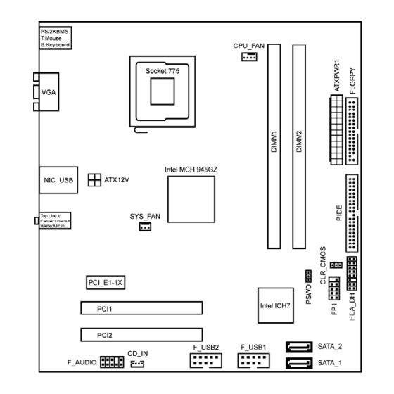
Page 9: Layout
Chapter 1 Product Introduction Expansion Slots · Two PCI slots · One PCI Express x1 slot Layout Note: The above motherboard layout is provided for reference only, please refer to the physical motherboard. -
Page 10: Rear I/O Ports
Chapter 1 Product Introduction Rear I/O Ports This motherboard provides the ports as below: LAN Port (-L) Line-in (Rear) PS/2 Mouse Line-out Port (Front) PS/2 Key- Microphone (CEN/LFE) board Port USB2.0 Ports VGA Port Line-in jack,Line-out jack,Microphone jack When using a 2-channel sound source, the Line-out jack is used to connect to speaker or headphone;... -
Page 11: Cpu
Chapter 1 Product Introduction Chapter This chapter introduces the hardware installation process, in- cluding the installation of the CPU, memory, power supply, slots, and pin headers, an d the mount ing o f jumpers. Caution should be exercised during the installation of these modules. Please refer to the motherboard layout prior to any installation and read the contents in this chapter carefully. - Page 12 Chapter 2 Installation Instructions This motherboard supports Intel ® Core 2 Duo E4xx0 series(65W ), Pentium ® 9xx series(95W ), Pentium ® E2xxx series(65W ), Pentium ® 4 6x1 series(65W ), Celeron D 3xx series(65W), Celeron 4xx series(35W) processors in an LGA775 ®...
- Page 13 Chapter 2 Installation Instructions 3. Hold CPU with thumb and forefinger. Ensure fingers align to socket cutouts. Match the CPU triangle marker to Pin 1 position as shown below. The alignment key also provides the orientation directed function. Lower the CPU straight down without tilting or sliding the CPU in the socket.
- Page 14 Chapter 2 Installation Instructions 5. Close the load plate, and slightly push down the tongue side. 6. Lower the lever and lock it to the load plate, then the CPU is locked completely. Warning: Excessive temperatures will severely damage the CPU and system.
- Page 15 Chapter 2 Installation Instructions Memory This motherboard includes two 240-pin slots with 1.8V for DDR2. You must install at least one memory bank to ensure normal operation. For the detailed memory support list on this motherboard, please visit the website: http://www.foxconnchannel.com Installation of DDR2 Memory 1.
- Page 16 Chapter 2 Installation Instructions Power Supply This motherboard uses an ATX power supply. In order to avoid damaging any devices, make sure that they have been installed properly prior to connecting the power supply. +5V_AUX +3. 3V +12V +3.3V 24-pin ATX power connector: PWR1 +12V + 3 .
-
Page 17: Fdd/Ide Connector
Chapter 2 Installation Instructions Other Connectors This motherboard includes connectors for FDD devices, IDE devices, Serial ATAII devices, USB devices, and others. FDD Connector: FLOPPY This motherboard includes a standard FDD connector FLOPPY, supporting [360K, 5.25in], [1.2M, 5.25in], [720K, 3.5in], [1.44M, 3.5in] and [2.88M, 3.5in] floppy disks. IDE Connector: PIDE The PIDE connector supports Ultra ATA 100/66 IDE hard disk drives. -
Page 18: Front Panel Connector
Chapter 2 Installation Instructions Front Panel Connector: FP1 PW R SW This motherboard includes one connector for con- Empt y PW RL ED necting the front panel switch and LED indicators. HD-L ED R E S E T HDD LED Connector (HD-LED) The connector connects to the case’s HDD indicator LED indicating the activity status of hard disks. -
Page 19: Expansion Slots
Chapter 2 Installation Instructions BCLK 3D3V_SYS RST# SYNC HD Audio Digital Connector: HDA_DH 3.3V_DVDD_CORE +12V The connector is intel ® HD Audio Digital Header. RSVD 3D3V_DUAL RSVD RSVD HDA_DH Expansion Slots This motherboard includes two 32-bit master PCI bus slots, one PCI Express x1 slot. -
Page 20: Jumpers
Chapter 2 Installation Instructions Jumpers The users can change the jumper settings on this motherboard if needed. This section explains how to use the various functions of this motherboard by chang- ing the jumper settings. Users should read the following content carefully prior to modifying any jumper settings. -
Page 21: Chapter 3 Bios Description
Chapter 3 BIOS Description Chapter This chapter tells how to change system settings through the BIOS Setup menus. Detailed descriptions of the BIOS param- eters are also provided. You have to run the Setup Utility when the following cases occur: 1. - Page 22 Chapter 3 BIOS Description Enter BIOS Setup The BIOS is the communication bridge between hardware and software, correctly setting up the BIOS parameters is critical to maintain optimal system performance. Power on the computer, when the following message briefly appears at the bottom of the screen during the POST (Power On Self Test), press <Del>...
- Page 23 Chapter 3 BIOS Description vSystem Date This option allows you to set the desired date (usually as the current day) with the <day><month><date><year> format. Day—weekday from Sun. to Sat., defined by BIOS (read-only). Month—month from Jan. to Dec.. Date—date from 1 to 31 , can be changed using the keyboard.
-
Page 24: Advanced Menu
Chapter 3 BIOS Description Advanced Menu Advanced Menu vPrimary Video Adapter Press <Enter> to select which Video Adapter to display. vOnboard Video Memory Size Select the amount of system memory used by the internal graphics device. vPS/2 Mouse Select [Auto Detect] to auto detect PS/2 mouse; Select [Enabled] to enable and support PS/2 mouse function;... - Page 25 Chapter 3 BIOS Description vSupervisor/User Password The access rights and permissions associated with the supervisor password are higher than those of a regular user password. The supervisor password is used to authorize the capability to change BIOS setup options. The user pass word is used to authorize the capability to change non-critical BIOS setup options only, such as system date and system time.
-
Page 26: Power Menu
Chapter 3 BIOS Description Power Menu Power Menu vAfter AC Power Failure The option is used to set the mode of operation if an AC Power Loss occurs. [Stay Off] keeps the power off until the power button is pressed. [Power On] restores power as soon as AC is applied. -
Page 27: Boot Menu
Chapter 3 BIOS Description Boot Menu Boot Menu vBoot-time Diagnostic Screen The option is used to display the diagnostic screen during boot. vBoot Device Priority Press <Enter> to select the search order for the types of boot devices. Boot Device Priority... -
Page 28: Exit Menu
Chapter 3 BIOS Description v1st/2nd/3rd/4th Boot Device These items specify the boot device sequence from the available devices. The number of device items that appears on the screen depends on the number of devices installed in the system. vFloppy/CD-ROM/Hard Drive/Network Group Boot Priority Those settings allow you to set the boot priority of the floppy group and CD/ DVD drives group and hard drives group and network group installed in the system. - Page 29 Chapter 3 BIOS Description vDiscard Changes This option allows you to discard the selections you made and load previous values from CMOS for all setup items. vSave Changes Select YES to save changes to CMOS and exit.
Need help?
Do you have a question about the 945GZ7MC and is the answer not in the manual?
Questions and answers