Table of Contents
Advertisement
Advertisement
Table of Contents

Related Manuals for Asus P5K-VM


Summary of Contents for Asus P5K-VM
- Page 1 P5K-VM...
- Page 2 Product warranty or service will not be extended if: (1) the product is repaired, modified or altered, unless such repair, modification of alteration is authorized in writing by ASUS; or (2) the serial number of the product is defaced or missing.
-
Page 3: Table Of Contents
Contents Notices ... vi Safety information ... vii P5K-VM specifications summary ... x Chapter 1: Product introduction Welcome! ... 1-2 Package contents ... 1-2 Special features ... 1-3 1.3.1 Product highlights ... 1-3 1.3.2 ASUS AI Lifestyle features ... 1-5 1.3.3... - Page 4 2.1.1 ASUS Update utility ... 2-2 2.1.2 Creating a bootable floppy disk ... 2-5 2.1.3 ASUS EZ Flash 2 utility ... 2-6 2.1.4 AFUDOS utility ... 2-7 2.1.5 ASUS CrashFree BIOS 3 utility ... 2-9 BIOS setup program ... 2-10 2.2.1...
- Page 5 2.6.2 Boot Settings Configuration ... 2-32 2.6.3 Security ... 2-33 Tools menu ... 2-35 2.7.1 ASUS EZ Flash 2 ... 2-35 2.7.2 AI Net 2 ... 2-36 Exit menu ... 2-37 Chapter 3: Software support Installing an operating system ... 3-2 Support CD information ...
-
Page 6: Federal Communications Commission Statement
Notices Federal Communications Commission Statement This device complies with Part 15 of the FCC Rules. Operation is subject to the following two conditions: • This device may not cause harmful interference, and • This device must accept any interference received including interference that may cause undesired operation. -
Page 7: Electrical Safety
Safety information Electrical safety • To prevent electrical shock hazard, disconnect the power cable from the electrical outlet before relocating the system. • When adding or removing devices to or from the system, ensure that the power cables for the devices are unplugged before the signal cables are connected. -
Page 8: Where To Find More Information
Refer to the following sources for additional information and for product and software updates. ASUS websites The ASUS website provides updated information on ASUS hardware and software products. Refer to the ASUS contact information. Optional documentation Your product package may include optional documentation, such as warranty flyers, that may have been added by your dealer. -
Page 9: Conventions Used In This Guide
Conventions used in this guide To make sure that you perform certain tasks properly, take note of the following symbols used throughout this manual. DANGER/WARNING: Information to prevent injury to yourself when trying to complete a task. CAUTION: Information to prevent damage to the components when trying to complete a task. -
Page 10: P5K-Vm Specifications Summary
- Supports up to 8 GB system memory * The chipset officially supports the memory frequency up to DDR2 800MHz. Tuned by the ASUS Super Memspeed Technology, this motherboard natively supports up to DDR2 1066MHz. Refer to www.asus.com or this user manual for the Memory QVL (Qualified Vendors Lists). - Page 11 - Memory tuning from 667MHz to 1333MHz for DDR2 - PCI-E frequency tuning from 100MHz to 150MHz at 1 MHz increment Overclocking protection: - ASUS C.P.R. (CPU Parameter Recall) 1 x PS/2 keyboard port 1 x Parallel port 1 x Coaxial S/PDIF Out port...
- Page 12 *Specifications are subject to change without notice. 8 Mb Flash ROM, AMI BIOS, PnP, DMI2.0, WfM2.0, SM BIOS 2.3, ACPI 2.0a, ASUS CrashFree BIOS 3, ASUS EZ Flash 2 WfM 2.0, DMI 2.0, WOL by PME, WOR by PME, PXE...
-
Page 13: Chapter 1: Product Introduction
This chapter describes the motherboard features and the new technologies it supports. Product introduction... -
Page 14: Welcome
Thank you for buying an ASUS The motherboard delivers a host of new features and latest technologies, making it another standout in the long line of ASUS quality motherboards! Before you start installing the motherboard, and hardware devices on it, check the items in your package with the list below. -
Page 15: Special Features
Green ASUS This motherboard and its packaging comply with the European Union’s Restriction on the use of Hazardous Substances (RoHS). This is in line with the ASUS vision of creating environment-friendly and recyclable products/packaging to safeguard consumers’ health while minimizing the impact on the environment. -
Page 16: High Definition Audio
Native DDR2 1066 memory support To attain top performance, ASUS engineers have successfully unleashed the true potential of DDR2 memory. While in DDR2 1066 mode, ASUS’s exclusive technology offers a choice of FSB 1333, providing great performance for 3D graphics and other memory demanding applications. See page 1-17 for details. -
Page 17: Asus Ai Lifestyle Features
ASUS EZ DIY ASUS EZ DIY feature collection provides you easy ways to install computer components, update the BIOS or back up your favorite settings. ASUS Q-Connector ASUS Q-Connector allows you to easily connect or disconnect the chassis front panel cables to the motherboard. -
Page 18: Asus Stylish Features
Smart Support CD It provides a checklist to allow the user to see which drivers are already installed, as well as those that aren’t. When using ASUS PC Probe II, you can easily see the critical parts of the computer. -
Page 19: Before You Proceed
ON, in sleep mode, or in soft-off mode. This is a reminder that you should shut down the system and unplug the power cable before removing or plugging in any motherboard component. The illustration below shows the location of the onboard LED. P5K-VM Onboard LED ASUS P5K-VM SB_PWR Standby... -
Page 20: Motherboard Overview
Motherboard overview Before you install the motherboard, study the configuration of your chassis to ensure that the motherboard fits into it. Make sure to unplug the power cord before installing or removing the motherboard. Failure to do so can cause you physical injury and damage motherboard components. -
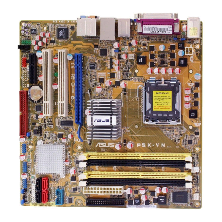
Page 21: Product Layout
PCIEX16_1 PCI1 VT6308S SB_PWR PCI2 PCIEX4_1 ALC883 IE1394_2 AAFP Refer to 1.10 Connectors for more information about rear panel connectors and internal connectors. ASUS P5K-VM 24.4cm (9.6in) LGA775 ® Intel JMicron CR2032 3V Lithium Cell JMB368 BIOS CMOS Power PRI_EIDE... -
Page 22: Central Processing Unit (Cpu)
ASUS will shoulder the cost of repair only if the damage is shipment/transit-related. • Keep the cap after installing the motherboard. ASUS will process Return Merchandise Authorization (RMA) requests only if the motherboard comes with the cap on the LGA775 socket. -
Page 23: Installing The Cpu
Installing the CPU To install a CPU: Locate the CPU socket on the motherboard. P5K-VM CPU Socket 775 Before installing the CPU, make sure that the cam box is facing towards you and the load lever is on your left. - Page 24 Lift the load plate with your thumb and forefinger to a 100º angle (A), then push the PnP cap from the load plate window to remove (B). Position the CPU over the socket, making sure that the gold triangle is on the bottom-left corner of the socket then fit the socket alignment key into the...
-
Page 25: Installing The Cpu Heatsink And Fan
CPU fan connector. Make sure to orient each fastener with the narrow end of the groove pointing outward. (The photo shows the groove shaded for emphasis.) ASUS P5K-VM processor, the package includes the CPU fan ® Motherboard hole... - Page 26 Connect the CPU fan cable to the connector on the motherboard labeled CPU_FAN. P5K-VM CPU fan connector Do not forget to connect the CPU fan connector! Hardware monitoring errors can occur if you fail to plug this connector.
-
Page 27: Uninstalling The Cpu Heatsink And Fan
Rotate each fastener counterclockwise. Pull up two fasteners at a time in a diagonal sequence to disengage the heatsink and fan assembly from the motherboard. Carefully remove the heatsink and fan assembly from the motherboard. ASUS P5K-VM 1-15... - Page 28 Rotate each fastener clockwise to ensure correct orientation when reinstalling. The narrow end of the groove should point outward after resetting. (The photo shows the groove shaded for emphasis.) Refer to the documentation in the boxed or stand-alone CPU fan package for detailed information on CPU fan installation.
-
Page 29: System Memory
Channel Channel A DIMM_A1 and DIMM_A2 Channel B DIMM_B1 and DIMM_B2 • This chipset officially supports DDR2-800 MHz. With the ASUS Super Memspeed Technology, this motherboard natively supports up to DDR2-1066 MHz. See the table below. 1333 1333 1333 1066... -
Page 30: Memory Configurations
1.7.2 Memory configurations You may install 256 MB, 512 MB, 1 GB, and 2 GB unbuffered non-ECC DDR2 DIMMs into the DIMM sockets. Recommended Memory Configurations Mode Single-Channel Dual-channel (1) Dual-channel (2) • You may install varying memory sizes in Channel A and Channel B. The system maps the total size of the lower-sized channel for the dual-channel configuration. - Page 31 • C*: Supports 4 modules inserted into both the yellow and black slots as two pairs of Dual-channel memory configuration. Visit the ASUS website for the latest DDR2-1066/800/667MHz QVL. ASUS P5K-VM Part No. OCZ2P10002GK / PC2 8000 / 1G EL Dual CH /Gold XTC BL646AA1005.8FD / CL111R5W6-65183...
- Page 32 P5K-VM Motherboard Qualified Vendors Lists (QVL) DDR2-800 MHz capability Size Vendor 512MB KINGSTON 1024MB KINGSTON 1024MB KINGSTON 1024MB KINGSTON 256MB Qimonda 512MB Qimonda 1024MB Qimonda 512MB SAMSUNG 256MB SAMSUNG 512MB SAMSUNG 1024MB SAMSUNG 512MB Hynix 1024MB Hynix 512MB MICRON 1024MB...
- Page 33 P5K-VM Motherboard Qualified Vendors Lists (QVL) DDR2-667MHz capability Size Vendor Chip No. 512MB KINGSTON D6408TEBGGL3U 1024MB KINGSTON D6408TEBGGL3U 256MB KINGSTON HYB18T256800AF3S 256MB KINGSTON 6SBI2D9DCG 2048MB KINGSTON E1108AB-6E-E 512MB Qimonda HYB18T512800BF3S(ECC) 1024MB Qimonda HYB18T512800BF3S(ECC) 256MB Qimonda HYB18T512160BF-3S 512MB Qimonda HYB18T512800BF3S 1024MB...
-
Page 34: Installing A Dimm
1.7.3 Installing a DIMM Unplug the power supply before adding or removing DIMMs or other system components. Failure to do so can cause severe damage to both the motherboard and the components. To install a DIMM: Unlock a DIMM socket by pressing the retaining clips outward. -
Page 35: Expansion Slots
IRQ” or that the cards do not need IRQ assignments. Otherwise, conflicts will arise between the two PCI groups, making the system unstable and the card inoperable. Refer to the table on the next page for details. ASUS P5K-VM 1-23... -
Page 36: Interrupt Assignments
1.8.3 Interrupt assignments Priority – * These IRQs are usually available for PCI devices. IRQ assignments for this motherboard PCI slot 1 PCI slot 2 LAN (Marvell8056) PATA (368) PCIE x16_1 PCIE x4 USB controller 0 USB controller 1 USB controller 2 USB controller 3 USB controller 4 USB controller 5... -
Page 37: Pci Slots
Internal Graphics Mode Select item in BIOS to [Disabled]. See section 2.4.4 Chipset for details. The PCI Express x16 slot supports PCIE x16 graphics cards only. You may not install x8, x4, or x1 cards to this slot. ASUS P5K-VM PCI Express x4 slot PCI slot PCI slot... -
Page 38: Clear Rtc Ram
Except when clearing the RTC RAM, never remove the cap on CLRTC jumper default position. Removing the cap will cause system boot failure! P5K-VM Clear RTC RAM You do not need to clear the RTC when the system hangs due to overclocking. - Page 39 ATX power supply that can supply at least 1A on the +5VSB lead, and a corresponding setting in the BIOS. P5K-VM Keyboard power setting USB device wake-up (3-pin USBPW1-4, USBPW5-8, USBPW9-12) Set these jumpers to +5V to wake up the computer from S1 sleep mode (CPU stopped, DRAM refreshed, system running in low power mode) using the connected USB devices.
-
Page 40: Lan Port Led Indications
1.10 Connectors 1.10.1 Rear panel connectors PS/2 keyboard port (purple). This port is for a PS/2 keyboard. Parallel port. This 25-pin port connects a parallel printer, a scanner, or other devices. IEEE1394a port. This 6-pin IEEE 1394a port provides high-speed connectivity for audio/video devices, storage peripherals, PCs, or portable devices. - Page 41 14. Coaxial S/PDIF Out port. This port connects an external audio output device via a coaxial S/PDIF cable. 15. USB 2.0 ports 5 and 6. These two 4-pin Universal Serial Bus (USB) ports 5re available for connecting USB 2.0 devices. ASUS P5K-VM 6-channel 8-channel Line In...
-
Page 42: Internal Connectors
Pin 5 on the connector is removed to prevent incorrect cable connection when using a FDD cable with a covered Pin 5. P5K-VM Floppy disk drive connector 1-30 FLOPPY PIN 1 NOTE: Orient the red markings on the floppy ribbon cable to PIN 1. -
Page 43: Ide Connectors
• Use the 80-conductor IDE cable for Ultra DMA 133/100/66 IDE devices. If any device jumper is set as “Cable-Select,” make sure all other device jumpers have the same setting. P5K-VM IDE connector ASUS P5K-VM Mode of Cable connector device(s) - Page 44 (7-pin SATA1 [red], SATA2 [black], SATA3 [red], SATA4 [black]) These connectors are for the Serial ATA signal cables for Serial ATA hard disk drives. P5K-VM SATA connectors Connect the right-angle side of SATA signal cable to SATA device. Or you may connect the...
- Page 45 Never connect a 1394 cable to the USB connectors. Doing so will damage the motherboard! You can connect the front panel USB cable to the ASUS Q-Connector (USB, blue) first, and then install the Q-Connector (USB) to the USB connector onboard if your chassis supports front panel USB ports.
- Page 46 Never connect a USB cable to the IEEE 1394a connector. Doing so will damage the motherboard! You can connect the front panel 1394 cable to the ASUS Q-Connector (1394, red) first, and then install the Q-Connector (1394) to the 1394 connector onboard if your chassis supports front panel 1394 ports.
- Page 47 Do not place jumper caps on the fan connectors! P5K-VM Fan connectors Only the CPU-FAN connectors support the ASUS Q-FAN feature. Serial port connector (10-1 pin COM1) This connector is for a serial (COM) port. Connect the serial port module cable to this connector, then install the module to a slot opening at the back of the system chassis.
- Page 48 HD Audio or legacy AC`97 audio standard. Connect one end of the front panel audio I/O module cable to this connector. P5K-VM Analog front panel connector • We recommend that you connect a high-definition front panel audio module to this connector to avail of the motherboard’s high-definition audio capability.
- Page 49 Find the proper orientation and push down firmly until the connectors completely fit. P5K-VM ATX power connectors • For a fully configured system, we recommend that you use a power supply unit (PSU) that complies with ATX 12 V Specification 2.0 (or later version)
-
Page 50: System Panel Connector
13. System panel connector (20-8 pin PANEL) This connector supports several chassis-mounted functions. P5K-VM System panel connector • System power LED (2-pin PLED) This 2-pin connector is for the system power LED. Connect the chassis power LED cable to this connector. The system power LED lights up when you turn on the system power, and blinks when the system is in sleep mode. - Page 51 Q-Connector (system panel) You can use ASUS Q-Connector to connect / disconnect chassis front panel cables by only a few steps. Directions below shows how to install ASUS Q- Connector. Step1. Connect correct front panel to ASUS Q- Connector first. You can refer to the marking on Q-Connector itself to know the detail pin definition.
- Page 52 1-40 Chapter 1: Product introduction...
-
Page 53: Chapter 2: Bios Setup
This chapter tells how to change the system settings through the BIOS Setup menus. Detailed descriptions of the BIOS parameters are also provided. BIOS setup... -
Page 54: Managing And Updating Your Bios
Input/Output System (BIOS) setup. ASUS Update (Updates the BIOS in Windows ASUS EZ Flash 2 (Updates the BIOS using a floppy disk or USB flash disk.) ASUS AFUDOS (Updates the BIOS using a bootable floppy disk.) ASUS CrashFree BIOS 3 (Updates the BIOS using a bootable floppy disk, USB flash disk or the motherboard support CD when the BIOS file fails or gets corrupted.) - Page 55 Updating the BIOS through the Internet To update the BIOS through the Internet: Launch the ASUS Update utility from the Windows > Programs > ASUS > ASUSUpdate > ASUSUpdate. The ASUS Update main window appears. Select Update BIOS from the Internet option from the drop-down menu, then click Next.
- Page 56 Updating the BIOS through a BIOS file To update the BIOS through a BIOS file: Launch the ASUS Update utility from the Windows > Programs > ASUS > ASUSUpdate > ASUSUpdate. The ASUS Update main window appears. Select Update BIOS from a file option from the drop-down menu, then click Next.
-
Page 57: Creating A Bootable Floppy Disk
Disk window appears. e. Select Create an MS-DOS startup disk from the format options field, then click Start. Copy the original or the latest motherboard BIOS file to the bootable floppy disk. ASUS P5K-VM desktop, then select My Computer. ®... -
Page 58: Asus Ez Flash 2 Utility
2.1.3 ASUS EZ Flash 2 utility The ASUS EZ Flash 2 feature allows you to update the BIOS without having to go through the long process of booting from a floppy disk and using a DOS-based utility. The EZ Flash 2 utility is built-in the BIOS chip so it is accessible by pressing <Alt>... -
Page 59: Afudos Utility
The utility returns to the DOS prompt after copying the current BIOS file. Updating the BIOS file To update the BIOS file using the AFUDOS utility: Visit the ASUS website (www.asus.com) and download the latest BIOS file for the motherboard. Save the BIOS file to a bootable floppy disk. ASUS P5K-VM... - Page 60 A:\>afudos /iP5K-VM.ROM The utility verifies the file and starts updating the BIOS. A:\>afudos /iP5K-VM.ROM AMI Firmware Update Utility - Version 1.19(ASUS V2.07(03.11.24BB)) Copyright (C) 2002 American Megatrends, Inc. All rights reserved. WARNING!! Do not turn off power during flash BIOS Reading file ...
-
Page 61: Asus Crashfree Bios 3 Utility
2.1.5 ASUS CrashFree BIOS 3 utility The ASUS CrashFree BIOS 3 is an auto recovery tool that allows you to restore the BIOS file when it fails or gets corrupted during the updating process. You can update a corrupted BIOS file using the motherboard support CD, the floppy disk, or the USB flash disk that contains the updated BIOS file. -
Page 62: Bios Setup Program
The BIOS setup screens shown in this section are for reference purposes only, and may not exactly match what you see on your screen. • Visit the ASUS website (www.asus.com) to download the latest BIOS file for this motherboard. 2-10... -
Page 63: Bios Menu Screen
At the bottom right corner of a menu screen are the navigation keys for that particular menu. Use the navigation keys to select items in the menu and change the settings. Some of the navigation keys differ from one screen to another. ASUS P5K-VM Configuration fields BIOS SETUP UTILITY Boot... -
Page 64: Menu Items
2.2.4 Menu items The highlighted item on the menu bar displays the specific items for that menu. For example, selecting Main shows the Main menu items. The other items (Advanced, Power, Boot, and Exit) on the menu bar have their respective menu items. 2.2.5 Sub-menu items A solid triangle before each item on any menu screen means that the iteam has a... -
Page 65: Main Menu
System Date [Day xx/xx/xxxx] Allows you to set the system date. 2.3.3 Legacy Diskette A [1.44M, 3.5 in.] Sets the type of floppy drive installed. Configuration options: [Disabled] [720K, 3.5 in.] [1.44M, 3.5 in.] ASUS P5K-VM BIOS SETUP UTILITY Boot Tools Exit [10:55:25] [Wed 05/10/2007] [1.44M, 3.5 in]... -
Page 66: Sata 1~4; Pata Primary Master/Slave
2.3.4 SATA 1~4; PATA Primary Master/Slave While entering Setup, the BIOS automatically detects the presence of IDE devices. There is a separate sub-menu for each IDE device. Select a device item then press <Enter> to display the IDE device information. Main SATA 1 Device... -
Page 67: Ide Configuration
Sets the configuration for the Serial ATA connectors supported by the Southbridge chip. If you want to use the Serial ATA hard disk drives as Parallel ATA physical storage devices, keep the defaul setting [IDE]. ASUS P5K-VM [Enhanced] [IDE] [Disabled]... -
Page 68: Hard Disk Write Protect [Disabled]
Hard Disk Write Protect [Disabled] Disables or enables device write protection. This will be effective only if device is accessed throuh BIOS. Confiuration option: [Disabled] [Enabled] SATA Detect Time Out (Sec) [35] Selects the time out value for detecting ATA/ATAPI devices. Configuration options: [0] [5] [10] [15] [20] [25] [30] [35] 2.3.6 System Information... -
Page 69: Advanced Menu
Select any one of the preset overclocking configuration options: Manual Allows you to individually set overclocking parameters. Auto Loads the optimal settings for the system. Standard Loads the standard settings for the system. ASUS P5K-VM BIOS SETUP UTILITY Boot Tools Exit [Auto] [Auto]... - Page 70 Some of the following items appear when you set AI Overclocking to [Manual]. CPU Ratio Control [Auto] Configuration options: [Auto] [Manual] The following item appears when the CPU Ratio Control item is set to [Manual]. Ratio CMOS Setting [12] Use the <+> and <-> keys to select the CMOS ratio values from 6 to 12. FSB Frequency [XXX] Displays the frequency sent by the clock generator to the system bus and PCI bus.
-
Page 71: Dram Static Read Control [Auto]
Configuration options: [Auto] [Disabled] [Enabled] CPU Spread Spectrum [Auto] Allows you to enable or disable the CPU spread spectrum. Configuration options: [Auto] [Disabled] PCIE Spread Spectrum [Auto] Allows you to enable or disable the PCIE spread spectrum. Configuration options: [Auto] [Disabled] ASUS P5K-VM 2-19... -
Page 72: Usb Configuration
CPU Voltage [Auto] Allows you to select the CPU voltage. Configuration options: [Auto] [1.6000V] [1.5875V] [1.5750V] [1.5625V] [1.5500V] [1.5375V] [1.5250V] [1.5125V] [1.5000V] [1.4875V] [1.4750V] [1.4625V] [1.4500V] [1.4375V] [1.4250V] [1.4125V] [1.4000V] [1.3875V] [1.3750V] [1.3625V] [1.3500V] [1.3375V] [1.3250V] [1.3125V] [1.3000V] [1.2875V] [1.2750V] [1.2625V] [1.2500V] [1.2375V] [1.2250V] [1.2125V] [1.2000V] [1.1875V] [1.1750V] [1.1625V] [1.1500V] Refer to the CPU documentation before setting the CPU voltage. - Page 73 USB devices at startup. If detected, the USB controller legacy mode is enabled. If no USB device is detected, the legacy USB support is disabled. Configuration options: [Disabled] [Enabled] [Auto] ASUS P5K-VM 2-21...
-
Page 74: Cpu Configuration
2.4.3 CPU Configuration The items in this menu show the CPU-related information that the BIOS automatically detects. Advanced Configure advanced CPU settings Manufacturer:Intel Brand String:Genuine Intel(R) CPU @ 2.40 GHz Frequency :2.40GHz FSB Speed :800 MHz Cache L1 :32 KB Cache L2 :512 KB CPUID... -
Page 75: Execute Disable Bit [Enabled]
Memory Remap Feature Initiate Graphic Adapter Internal Graphics Mode Select PEG Port Control PEG Port Force x1 Video Function Configuration v02.58 (C)Copyright 1985-2007, American Megatrends, Inc. ASUS P5K-VM BIOS SETUP UTILITY BIOS SETUP UTILITY [Enabled] [PEG/PCI] [Enabled, 8MB] [Auto] [Disabled] Configure North Bridge features. - Page 76 Memory Remap Feature [Enabled] Allows you to enabled or disable the remapping of the overlapped PCI memory above the total physical memory. Enable this option only when you install 64-bit operating system. Configuration options: [Disabled] [Enabled] Initiate Graphic Adapter [PEG/PCI] Allows you to decide which graphics controller to use as the primary boot device.
-
Page 77: Onboard Devices Configuration
Allows you to select the Serial Port1 base address. Configuration options: [Disabled] [3F8/IRQ4] [2F8/IRQ3] [3E8/IRQ4] [2E8/IRQ3] Parallel Port Address [378] Allows you to select the Parallel Port base addresses. Configuration options: [Disabled] [378] [278] [3BC] ASUS P5K-VM BIOS SETUP UTILITY [Enabled] [HD Audio] [Enabled]... -
Page 78: Parallel Port Mode [Ecp]
Parallel Port Mode [ECP] Allows you to select the Parallel Port mode. Configuration options: [Normal] [Bi-Directional] [EPP] [ECP] ECP Mode DMA Channel [DMA3] Appears only when the Parallel Port Mode item is set to [ECP]. This item allows you to set the parallel port ECP DMA. Configuration options: [DMA0] [DMA1] [DMA3] EPP Version [1.9] Appears only when the Parallel Port Mode item is set to [EPP]. -
Page 79: Power Menu
Allows you to enable or disable the Advanced Configuration and Power Interface (ACPI) support in the Advanced Programmable Interrupt Controller (APIC). When set to Enabled, the ACPI APIC table pointer is included in the RSDT pointer list. Configuration options: [Disabled] [Enabled] ASUS P5K-VM BIOS SETUP UTILITY Boot Tools... -
Page 80: Apm Configuration
2.5.5 APM Configuration APM Configuration Restore on AC Power Loss Power On By RTC Alarm Power On By External Modems Power On By PCI Devices Power On By PCIE Devices Power On By PS/2 Keyboard v02.58 (C)Copyright 1985-2007, American Megatrends, Inc. Restore On AC Power Loss [Power Off] When set to Power Off, the system goes into off state after an AC power loss. -
Page 81: Hardware Monitor
(RPM). If the fan is not connected to the motherboard, the field shows N/A. CPU Q-Fan Control [Enabled] Allows you to enable or disable the CPU Q-Fan controller. Configuration options: [Disabled] [Enabled] ASUS P5K-VM BIOS SETUP UTILITY [30ºC/86ºF] [36ºC/96.5ºF] [2311RPM]... - Page 82 The CPU Fan Profile item appears when you enable the CPU Q-Fan Control feature. CPU Fan Profile [Optimal] Allows you to set the appropriate performance level of the CPU Q-Fan. When set to [Optimal], the CPU fan automatically adjusts depending on the CPU temperature.
-
Page 83: Boot Menu
These items specify the boot device priority sequence from the available devices. The number of device items that appears on the screen depends on the number of devices installed in the system. Configuration options: [xxx Drive] [Disabled] ASUS P5K-VM BIOS SETUP UTILITY Boot Tools... -
Page 84: Boot Settings Configuration
This allows you to enable or disable the full screen logo display feature. Configuration options: [Disabled] [Enabled] Set this item to [Enabled] to use the ASUS MyLogo2 AddOn ROM Display Mode [Force BIOS] Sets the display mode for option ROM. -
Page 85: Security
Time Clock (RTC) RAM. See section 2.6 Jumper for information on how to erase the RTC RAM. After you have set a supervisor password, the other items appear to allow you to change other security settings. ASUS P5K-VM BIOS SETUP UTILITY Boot :Not Installed :Not Installed <Enter>... -
Page 86: Change User Password
Security Settings Supervisor Password User Password Change Supervisor Password User Access Level Change User Password Clear User Password Password Check v02.58 (C)Copyright 1985-2007, American Megatrends, Inc. User Access Level [Full Access] This item allows you to select the access restriction to the Setup items. Configuration options: [No Access] [View Only] [Limited] [Full Access] No Access prevents user access to the Setup utility. -
Page 87: Tools Menu
2.7.1 ASUS EZ Flash 2 Allows you to run ASUS EZ Flash 2. When you press <Enter>, a confirmation message appears. Use the left/right arrow key to select between [Yes] or [No], then press <Enter> to confirm your choice. Please see section 2.1.3 for details. -
Page 88: Ai Net 2
2.7.2 AI Net 2 Pair Status Length POST Check LAN cable v02.58 (C)Copyright 1985-2007, American Megatrends, Inc. POST Check LAN Cable [Disabled] Enables or disables checking of the LAN cable during the Power-On Self-Test (POST). Configuration options: [Disabled] [Enabled] 2-36 BIOS SETUP UTILITY Advanced [Disabled]... -
Page 89: Exit Menu
Setup menus. When you select this option or if you press <F5>, a confirmation window appears. Select YES to load default values. Select Exit & Save Changes or make other changes before saving the values to the non-volatile RAM. ASUS P5K-VM BIOS SETUP UTILITY Boot... - Page 90 2-38 Chapter 2: BIOS setup...
-
Page 91: Chapter 3: Software Support
This chapter describes the contents of the support CD that comes with the motherboard package. Software support ASUS P5K-VM... -
Page 92: Installing An Operating System
The contents of the support CD are subject to change at any time without notice. Visit the ASUS website (www.asus.com) for updates. 3.2.1 Running the support CD Place the support CD to the optical drive. -
Page 93: Drivers Menu
The drivers menu shows the available device drivers if the system detects installed devices. Install the necessary drivers to activate the devices. ASUS InstAll-Drivers Installation Wizard Installs the ASUS InstAll-Drivers Installation Wizard. Intel Chipset Inf Update Program Installs the Intel chipset Inf update program. -
Page 94: Utilities Menu
Installs all of the utilities through the Installation Wizard. ASUS Update Allows you to download the latest version of the BIOS from the ASUS website. Before using the ASUS Update, make sure that you have an Internet connection so you can connect to the ASUS website. - Page 95 You can also install the following utilities from the ASUS Superb Software Library CD. ADOBE Acrobat Reader V7.0 Installs the Adobe Acrobat ® documents in Portable Document Format (PDF). Microsoft DirectX 9.0c Installs the Microsoft DirectX 9.0 driver. The Microsoft DirectX ®...
-
Page 96: Manual Menu
3.2.5 ASUS Contact information Click the Contact tab to display the ASUS contact information. You can also find this information on the inside front cover of this user guide. Reader from the ASUS Superb Software Library CD before ®... -
Page 97: Other Information
The icons on the top right corner of the screen give additional information on the motherboard and the contents of the support CD. Click an icon to display the specified information. Motherboard Info Displays the general specifications of the motherboard. Browse this CD Displays the support CD contents in graphical format. ASUS P5K-VM... -
Page 98: Technical Support Form
Technical support Form Displays the ASUS Technical Support Request Form that you have to fill out when requesting technical support. Filelist Displays the contents of the support CD and a brief description of each in text format. Chapter 3: Software support...
Need help?
Do you have a question about the P5K-VM and is the answer not in the manual?
Questions and answers