Asus P5KPL-AM - SE Motherboard And Intel Core 2 Duo User Manual
User manual
Hide thumbs
Also See for P5KPL-AM - SE Motherboard And Intel Core 2 Duo:
- User manual (62 pages) ,
- Quick start manual (4 pages) ,
- User manual (62 pages)
Table of Contents
Advertisement
Advertisement
Table of Contents

Related Manuals for Asus P5KPL-AM - SE Motherboard And Intel Core 2 Duo


Summary of Contents for Asus P5KPL-AM - SE Motherboard And Intel Core 2 Duo
- Page 1 P5KPL-AM...
- Page 2 Product warranty or service will not be extended if: (1) the product is repaired, modified or altered, unless such repair, modification of alteration is authorized in writing by ASUS; or (2) the serial number of the product is defaced or missing.
-
Page 3: Table Of Contents
Welcome! ..................1-2 Package contents ................. 1-2 Special features ................1-2 1.3.1 Product highlights ............1-2 1.3.2 ASUS Special features ........... 1-4 Before you proceed ..............1-6 Motherboard overview ..............1-6 1.5.1 Placement direction ............1-7 1.5.2 Screw holes ..............1-7 1.5.3... - Page 4 Chapter 2: BIOS setup Managing and updating your BIOS ..........2-2 2.1.1 Creating a bootable floppy disk ........2-2 2.1.2 ASUS EZ Flash 2 utility ........... 2-3 2.1.3 AFUDOS utility ..............2-4 2.1.4 ASUS CrashFree BIOS 3 utility ........2-6 2.1.5...
- Page 5 2.6.2 Boot Settings Configuration .......... 2-31 2.6.3 Security ................. 2-32 Tools menu ................. 2-33 ASUS EZ Flash 2 ................. 2-34 Exit menu ..................2-34 Chapter 3: Software support Installing an operating system ........... 3-2 Support CD information .............. 3-2 3.2.1 Running the support CD ..........
-
Page 6: Notices
Notices Federal Communications Commission Statement This device complies with Part 15 of the FCC Rules. Operation is subject to the following two conditions: • This device may not cause harmful interference, and • This device must accept any interference received including interference that may cause undesired operation. -
Page 7: Safety Information
Safety information Electrical safety • To prevent electrical shock hazard, disconnect the power cable from the electrical outlet before relocating the system. • When adding or removing devices to or from the system, ensure that the power cables for the devices are unplugged before the signal cables are connected. -
Page 8: About This Guide
Refer to the following sources for additional information and for product and software updates. ASUS websites The ASUS website provides updated information on ASUS hardware and software products. Refer to the ASUS contact information. Optional documentation Your product package may include optional documentation, such as warranty flyers, that may have been added by your dealer. -
Page 9: Conventions Used In This Guide
Conventions used in this guide To make sure that you perform certain tasks properly, take note of the following symbols used throughout this manual. DANGER/WARNING: Information to prevent injury to yourself when trying to complete a task. CAUTION: Information to prevent damage to the components when trying to complete a task. -
Page 10: P5Kpl-Am Specifications Summary
05B / 05A / 06 processors ® Intel Hyper-Threading Technology ready ® Support Intel EIST technology ® Refer to www.asus.com for Intel CPU support list Chipset Northbridge: Intel ® Southbridge: Intel ICH7 ® Front Side Bus 1600(OC) / 1333 / 1066 / 800 MHz... - Page 11 8 Mb Flash ROM, AMI BIOS, PnP, DMI2.0, WfM2.0, ACPI V2.0a, SM BIOS 2.5 Manageability WO_USB, WO_KB/MS, WOR by Ring, PME Wake Up Support CD contents Drivers ASUS PC Probe II ASUS Update utility Anti-virus software Accessories 1 x Serial ATA cable 1 x Serial ATA power cable...
-
Page 13: Chapter 1: Product Introduction
This chapter describes the motherboard features and the new technologies it supports. Product introduction... -
Page 14: Welcome
Green ASUS This motherboard and its packaging comply with the European Union’s Restriction on the use of Hazardous Substances (RoHS). This is in line with the ASUS vision of creating environment-friendly and recyclable products/packaging to safeguard consumers’ health while minimizing the impact on the environment. - Page 15 USB 2.0 is the latest connectivity standard for next generation components and peripherals. Backwards compatible with current USB 1.1 peripherals, USB 2.0 delivers transfer speeds up to 40 times faster at 480Mb/s, for easy connectivity and ultra-fast data transfers. ASUS P5KPL-AM...
-
Page 16: Asus Special Features
ASUS CrashFree BIOS 3 Simply restore corrupted BIOS data from USB flash disk The ASUS CrashFree BIOS 3 allows users to restore corrupted BIOS data from a USB flash disk containing the BIOS file. This utility saves users the cost and hassle of buying a replacement BIOS chip. - Page 17 BIOS automatically restores the CPU default setting for each parameter. ASUS O.C. Profile The motherboard features the ASUS O.C. Profile that allows users to conveniently store or load multiple BIOS settings. The BIOS settings can be stored in the CMOS or a separate file, giving users freedom to share and distribute their favorite settings.
-
Page 18: Before You Proceed
Before you proceed Take note of the following precautions before you install motherboard components or change any motherboard settings. • Unplug the power cord from the wall socket before touching any component. • Use a grounded wrist strap or touch a safely grounded object or a metal object, such as the power supply case, before handling components to avoid damaging them due to static electricity. -
Page 19: Motherboard Overview
Screw holes Place six (6) screws into the holes indicated by circles to secure the motherboard to the chassis. Do not overtighten the screws! Doing so can damage the motherboard. Place this side towards the rear of the chassis ASUS P5KPL-AM... -
Page 20: Motherboard Layout
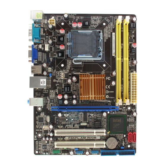
1.5.3 Motherboard layout 20.3cm (8in) PS/2KBMS T: Mouse CHA_FAN B: Keyboard ATX12V COM1 LGA775 VGA1 USB34 LAN1_USB12 Intel G31 RTM870T-954 AUDIO PCIEX1_1 PCIEX16 8102EL CR2032 3V Lithium Cell CMOS Power PCI1 Intel ICH7 SB_PWR PCI2 VT1708B SPDIF_OUT USB56 USB78 BIOS CLRTC AAFP Refer to section 1.10 Connectors for more information about rear panel... -
Page 21: Layout Contents
CPU, chassis fan connectors (4-pin CPU_FAN, 1-33 3-pin CHA_FAN) Chassis intrusion connector (4-1 pin CHASSIS) 1-34 10. Front panel audio connector (10-1 pin AAFP) 1-34 11. ATX power connectors (24-pin EATXPWR, 4-pin ATX 12V) 1-35 12. System panel connector (10-1 pin F_PANEL) 1-36 ASUS P5KPL-AM... -
Page 22: Central Processing Unit (Cpu)
ASUS will shoulder the cost of repair only if the damage is shipment/transit-related. • Keep the cap after installing the motherboard. ASUS will process Return Merchandise Authorization (RMA) requests only if the motherboard comes with the cap on the LGA775 socket. -
Page 23: Installing The Cpu
This side of the socket box should face you. To prevent damage to the socket pins, do not remove the PnP cap unless you are installing a CPU. Lift the load lever in the direction of the arrow to a 135º angle. ASUS P5KPL-AM 1-11... - Page 24 Lift the load plate with your thumb and forefinger to a 100º angle (A), then push the PnP cap from the load plate window to remove (B). Load plate Alignment key Position the CPU over the socket, making sure that the gold triangle is on the bottom-left corner of the socket then fit the socket...
-
Page 25: Installing The Cpu Heatsink And Fan
CPU fan connector. Motherboard hole Fastener Narrow end of the groove Make sure to orient each fastener with the narrow end of the groove pointing outward. (The photo shows the groove shaded for emphasis.) ASUS P5KPL-AM 1-13... - Page 26 Push down two fasteners at a time in a diagonal sequence to secure the heatsink and fan assembly in place. Connect the CPU fan cable to the connector on the motherboard labeled CPU_FAN. CPU_FAN CPU FAN PWM CPU FAN IN CPU FAN PWR P5KPL-AM CPU Fan Connector Do not forget to connect the CPU fan connector! Hardware monitoring errors...
-
Page 27: Uninstalling The Cpu Heatsink And Fan
Rotate each fastener counterclockwise. Pull up two fasteners at a time in a diagonal sequence to disengage the heatsink and fan assembly from the motherboard. Carefully remove the heatsink and fan assembly from the motherboard. ASUS P5KPL-AM 1-15... - Page 28 Rotate each fastener clockwise to ensure correct orientation when reinstalling. Narrow end of the groove The narrow end of the groove should point outward after resetting. (The photo shows the groove shaded for emphasis.) Refer to the documentation in the boxed or stand-alone CPU fan package for detailed information on CPU fan installation.
-
Page 29: System Memory
The figure illustrates the location of the DDR2 DIMM sockets: P5KPL-AM 240-pin DDR2 DIMM Sockets Channel Sockets Channel A DIMM_A1 Channel B DIMM_B1 Install a memory module in DIMM_A1 slot to support the Intel ® Quiet System Technology and for optimum performance. ASUS P5KPL-AM 1-17... -
Page 30: Memory Configurations
1.7.2 Memory configurations You may install 256 MB, 512 MB, 1 GB and 2 GB unbuffered non-ECC DDR2 DIMMs into the DIMM sockets. • You may install varying memory sizes in Channel A and Channel B. The system maps the total size of the lower-sized channel for the dual-channel configuration. - Page 31 512MB VDATA M2YVD5G3H31P4I1C52 VDATA VD29608A8A-3EG20627 • • 512MB VDATA M2GVD5G3H166I1C52 VDATA VD29608A8A-3EG20637 • • VDATA M2GVD5G3I41P6I1C52 VDATA VD29608A8A-3EG20627 • • VDATA M2GVD5G3I41C4I1C52 VDATA VD29608A8A-3EC20620 • • VDATA M2GVD5G3I4176I1C52 VDATA VD29608A8A-3EG20641 • • 512MB PSC AL6E8E63B-6E1K A3R12E3GEF637BLC5N • • ASUS P5KPL-AM 1-19...
- Page 32 DDR2 667 DIMM support Size Vendor Model Brand Side(s) Part No. AL7E8E63B-6E1K A3R12E3GEF637BLC5N • • 256MB Nanya NT256T64UH4A1FY-3C Nanya NT5TU32M16AG-3C • • 512MB Nanya NT512T64U88A1BY-3C Nanya NT5TU64M8AE-3C • • 512MB MDT MDT 512MB 18D51280D-30648 • • MDT 1024MB 18D51200D-30646 • •...
- Page 33 • • 256MB Qimonda HYS64T32001HU-2.5-A Qimonda HYB18T256800AF25SSS49313 • • 512MB Qimonda HYS64T64020HU-2.5-A Qimonda HYB18T256800AF25SSS25063 • • Corsair CM2X1024-6400 Corsair Heat-Sink Package • • Corsair XMS2-6400 Corsair Heat-Sink Package • • Corsair XMS2-6400 Corsair Heat-Sink Package • • ASUS P5KPL-AM 1-21...
- Page 34 Micron 6QD22D9GCT • • Visit the ASUS website (www.asus.com) for the latest QVL. Side(s): SS - Single-sided DS - Double-sided DIMM support: Supports one module inserted into any slot as Single-channel memory configuration. Supports one pair of modules inserted into the yellow slots as one pair of Dual-channel memory configuration.
-
Page 35: Installing A Dimm
DIMM. Support the DIMM lightly with your fingers when pressing the retaining clips. The DIMM might get damaged when it flips out with DDR2 DIMM notch extra force. Remove the DIMM from the socket. ASUS P5KPL-AM 1-23... -
Page 36: Expansion Slots
Expansion slots In the future, you may need to install expansion cards. The following sub-sections describe the slots and the expansion cards that they support. Make sure to unplug the power cord before adding or removing expansion cards. Failure to do so may cause you physical injury and damage motherboard components. -
Page 37: Interrupt Assignments
— — — — Onboard USB 2.0 controller — — — — — — — shared Onboard HD audio shared — — — — — — — Onboard LAN — Used — — — — — — ASUS P5KPL-AM 1-25... -
Page 38: Pci Slots
1.8.4 PCI slots The PCI slots support cards such as a LAN card, SCSI card, USB card, and other cards that comply with PCI specifications. The figure shows a LAN card installed on a PCI slot. 1.8.5 PCI Express x1 slot This motherboard supports PCI Express x1 network cards, SCSI cards and other cards that comply with the PCI Express... -
Page 39: Jumpers
• Due to the chipset limitation, AC power off is required prior using C.P.R. function. You must turn off and on the power supply or unplug and plug the power cord before reboot the system. ASUS P5KPL-AM 1-27... -
Page 40: 1.10 Connectors
1.10 Connectors 1.10.1 Rear panel connectors PS/2 mouse port (green). This port is for a PS/2 mouse. Parallel port. This 25-pin port connects a parallel printer, a scanner, or other devices. LAN (RJ-45) port. Supported by Realtek 10/100 LAN controller, this port allows 10/100 connection to a Local Area Network (LAN) through a network hub. - Page 41 12. Video Graphics Adapter port. This 15-pin port is for a VGA monitor or other VGA-compatible devices. 13. Serial port. This 9-pin COM1 port is for pointing devices or other serial devices. 14. PS/2 keyboard port (purple). This port is for a PS/2 keyboard. ASUS P5KPL-AM 1-29...
-
Page 42: Internal Connectors
1.10.2 Internal connectors Floppy disk drive connector (34-1 pin FLOPPY) This connector is for the provided floppy disk drive (FDD) signal cable. Insert one end of the cable to this connector, then connect the other end to the signal connector at the back of the floppy disk drive. Pin 5 on the connector is removed to prevent incorrect cable connection when using a FDD cable with a covered Pin 5. -
Page 43: Ide Connectors
If any device jumper is set as “Cable-Select,” make sure all other device jumpers have the same setting. PRI_IDE NOTE: Orient the red markings (usually zigzag) on the ID ribbon cable to PIN 1. IDE Connector P5KPL-AM 240-pin ASUS P5KPL-AM 1-31... - Page 44 ICH7 Serial ATA connectors (7-pin SATA1, SATA2, SATA3, SATA4) These connectors are for the Serial ATA signal cables for Serial ATA hard disk drives. RSATA_RXP1 RSATA_RXP3 RSATA_RXP4 RSATA_RXP2 RSATA_RXN1 RSATA_RXN3 RSATA_RXN4 RSATA_RXN2 RSATA_TXN1 RSATA_TXN3 RSATA_TXN4 RSATA_TXN2 RSATA_TXP1 RSATA_TXP3 RSATA_TXP4 RSATA_TXP2 P5KPL-AM SATA Connectors right angle side Connect the right-angle side...
- Page 45 The USB module is purchased separately. Optical drive audio connector (4-pin CD) These connectors allow you to receive stereo audio input from sound sources such as a CD-ROM, TV tuner, or MPEG card. (black) P5KPL-AM Internal Audio Connector ASUS P5KPL-AM 1-33...
- Page 46 Do not place jumper caps on the fan connectors! CPU_FAN CHA_FAN CPU FAN PWM CPU FAN IN CPU FAN PWR CHA_FAN +12V Rotation P5KPL-AM Fan Connectors Only the CPU-FAN connector support the ASUS Advanced Q-Fan feature. 1-34 Chapter 1: Product introduction...
- Page 47 By default, this connector is set to HD Audio. If you want to connect a High Definition front panel audio module to this connector, set the Front Panel Support Type item in the BIOS to [HD Audio]. See section “2.4.4 Chipset” for details. ASUS P5KPL-AM 1-35...
- Page 48 11. ATX power connectors (24-pin EATXPWR, 4-pin ATX12V) These connectors are for ATX power supply plugs. The power supply plugs are designed to fit these connectors in only one orientation. Find the proper orientation and push down firmly until the connectors completely fit. EATXPWR ATX12V +12V DC...
-
Page 49: System Panel Connector (10-1 Pin F_Panel)
BIOS settings. Pressing the power switch for more than four seconds while the system is ON turns the system OFF. • Reset button (2-pin RESET) This 2-pin connector is for the chassis-mounted reset button for system reboot without turning off the system power. ASUS P5KPL-AM 1-37... - Page 50 1-38 Chapter 1: Product introduction...
-
Page 51: Chapter 2: Bios Setup
This chapter tells how to change the system settings through the BIOS Setup menus. Detailed descriptions of the BIOS parameters are also provided. BIOS setup ASUS P5KPL-AM... -
Page 52: Managing And Updating Your Bios
The following utilities allow you to manage and update the motherboard Basic Input/Output System (BIOS) setup. ASUS EZ Flash 2 (Updates the BIOS in DOS mode using a floppy disk or USB flash disk.) ASUS AFUDOS (Updates the BIOS in DOS mode using a bootable floppy disk.) -
Page 53: Asus Ez Flash 2 Utility
2.1.2 ASUS EZ Flash 2 utility The ASUS EZ Flash 2 feature allows you to update the BIOS without having to go through the long process of booting from a floppy disk and using a DOS-based utility. The EZ Flash 2 utility is built-in the BIOS chip so it is accessible by pressing <Alt>... -
Page 54: Afudos Utility
Extension name Press <Enter>. The utility copies the current BIOS file to the floppy disk. A:\>afudos /oOLDBIOS1.rom AMI Firmware Update Utility - Version 1.19(ASUS V2.07(03.11.24BB)) Copyright (C) 2002 American Megatrends, Inc. All rights reserved. Reading flash ..done Write to file..ok A:\>... -
Page 55: Updating The Bios File
Updating the BIOS file To update the BIOS file using the AFUDOS utility: Visit the ASUS website (www.asus.com) and download the latest BIOS file for the motherboard. Save the BIOS file to a bootable floppy disk. Write the BIOS filename on a piece of paper. You need to type the exact BIOS filename at the DOS prompt. -
Page 56: Asus Crashfree Bios 3 Utility
2.1.4 ASUS CrashFree BIOS 3 utility The ASUS CrashFree BIOS 3 is an auto recovery tool that allows you to restore the BIOS file when it fails or gets corrupted during the updating process. You can update a corrupted BIOS file using the motherboard support CD , the floppy disk or the USB flash disk that contains the updated BIOS file. -
Page 57: Recovering The Bios From The Support Cd
Restart the system after the utility completes the updating process. • Only the USB flash disk with FAT 32/16 format and single partition can support ASUS CrashFree BIOS 3. The device size should be smaller than 8GB. • DO NOT shut down or reset the system while updating the BIOS! Doing so... -
Page 58: Asus Update Utility
2.1.5 ASUS Update utility The ASUS Update is a utility that allows you to manage, save, and update the motherboard BIOS in Windows environment. The ASUS Update utility allows you ® • Save the current BIOS file • Download the latest BIOS file from the Internet •... - Page 59 To update the BIOS through the Internet: desktop by clicking Start Launch the ASUS Update utility from the Windows ® > Programs > ASUS > ASUSUpdate > ASUSUpdate. The ASUS Update main window appears. Select Update BIOS from Select the ASUS FTP site nearest...
- Page 60 To update the BIOS through a BIOS file: desktop by clicking Start Launch the ASUS Update utility from the Windows ® > Programs > ASUS > ASUSUpdate > ASUSUpdate. The ASUS Update main window appears. Select Update BIOS from a file option from the drop-down menu, then click Next.
-
Page 61: Bios Setup Program
The BIOS setup screens shown in this section are for reference purposes only, and may not exactly match what you see on your screen. • Visit the ASUS website (www.asus.com) to download the latest BIOS file for this motherboard. ASUS P5KPL-AM... -
Page 62: Bios Menu Screen
2.2.1 BIOS menu screen Menu items Menu bar Configuration fields General help Use [ENTER], [TAB] System Time [20:46:08] or [SHIFT-TAB] to System Date [Fri 02/08/2002] select a field. Legacy Diskette A [1.44M, 3.5 in] Use [+] or [-] to Primary IDE Master :[Not Detected] configure system time. -
Page 63: Menu Items
[Enabled] Change Option General Help screen. MPS Revision [1.4] Save and Exit Exit 2.2.9 General help Pop-up window At the top right corner of the menu screen is Scroll bar a brief description of the selected item. ASUS P5KPL-AM 2-13... -
Page 64: Main Menu
Main menu When you enter the BIOS Setup program, the Main menu screen appears, giving you an overview of the basic system information. Refer to section “2.2.1 BIOS menu screen” for information on the menu screen items and how to navigate through them. System Time [20:46:57] Use [ENTER], [TAB]... -
Page 65: Primary, Third And Fourth Ide Master/Slave
When set to [Disabled], the data transfer from and to the device occurs one sector at a time. Configuration options: [Disabled] [Auto] ASUS P5KPL-AM 2-15... -
Page 66: Ide Configuration
PIO Mode [Auto] Selects the PIO mode. Configuration options: [Auto] [0] [1] [2] [3] [4] DMA Mode [Auto] Selects the DMA mode. Configuration options: [Auto] SMART Monitoring [Auto] Sets the Smart Monitoring, Analysis, and Reporting Technology. Configuration options: [Auto] [Disabled] [Enabled] 32Bit Data Transfer [Enabled] Enables or disables 32-bit data transfer. -
Page 67: System Information
: Genuine Intel(R) CPU 2.80GHz Speed : 2800MHz Count System Memory Installed Size: 512MB Usable Size: 503MB AMI BIOS Displays the auto-detected BIOS information. Processor Displays the auto-detected CPU specification. System Memory Displays the auto-detected system memory. ASUS P5KPL-AM 2-17... -
Page 68: Advanced Menu
Advanced menu The Advanced menu items allow you to change the settings for the CPU and other system devices. Take caution when changing the settings of the Advanced menu items. Incorrect field values can cause the system to malfunction. JumperFree Configuration Adjust system USB Configuration frequency/voltage... - Page 69 Manually set ICH Chipset Voltage or set to Auto for safe mode. Configuration options: [Auto] [1.5V] [1.6V] Vcore Over Voltage [Auto] Manually set Vcore Voltage or set to Auto for safe mode. Configuration options: [Auto] [+50mv] [+100mv] [+150mv] ASUS P5KPL-AM 2-19...
-
Page 70: Usb Configuration
2.4.2 USB Configuration The items in this menu allows you to change the USB-related features. Select an item then press <Enter> to display the configuration options. USB Configuration Options Options Module Version - 2.24.0-13.4 Disabled 2 USB Ports USB Devices Enabled: 4 USB Ports None 6 USB Ports... -
Page 71: Cpu Configuration
Enable this item to boot legacy operating systems that cannot support CPUs with extended CPUID functions. Configuration options: [Disabled] [Enabled] Vanderpool Technology [Enabled] Enable this item when the processor supports Vanderpool technology. Users need to reset the computer to change the configuration of this item. Configuration options: [Disabled] [Enabled] ASUS P5KPL-AM 2-21... - Page 72 CPU TM function [Enabled] Enables or disables Intel® CPU Thermal Monitor (TM2) function, a CPU overheating protection function. When enabled, the CPU core frequency and voltage is reduced when the CPU is overheats. Configuration options: [Enabled] [Disabled] Execute Disable Bit [Enabled] Allows you to Enable/disable Execute Disable Function.
-
Page 73: Chipset
Allows you to select the amout of system memory used by the Interanal graphics device. Configuration options: [Disabled] [Enabled, 1MB] [Enabled, 8MB] PEG Port Configuration PEG Force x1 [Disabled] Allows you to enable or disable the PEG Forec x 1. Configuration options: [Enabled] [Disabled] ASUS P5KPL-AM 2-23... -
Page 74: Video Function Configuration
Video Function Configuration Video Function Configuration Options Options DVMT Mode Select [DVMT Mode] Fixed Mode DVMT/FIXED Memory [256MB] DVMT Mode DVMT Mode Select [DVMT Mode] Allows you to select the DVMT Mode. Configuration options: [Fixed Mode] [DVMT Mode] DVMT/FIXED Memory [256MB] Allows you to select the amount of the DVMT/FIXED Memory. -
Page 75: Onboard Devices Configuration
Appears only when the Parallel Port Mode is set to [ECP]. This item allows you to set the Parallel Port ECP DMA. Configuration options: [DMA0] [DMA1] [DMA3] Parallel Port IRQ [IRQ7] Allows you to select parallel port IRQ. Configuration options: [IRQ5] [IRQ7] ASUS P5KPL-AM 2-25... -
Page 76: Pci Pnp
2.4.6 PCI PnP The PCI PnP menu items allow you to change the advanced settings for PCI/PnP devices. The menu includes setting IRQ and DMA channel resources for either PCI/PnP or legacy ISA devices, and setting the memory size block for legacy ISA devices. -
Page 77: Power Menu
Allows you to enable or disable the Advanced Configuration and Power Interface (ACPI) support in the Application-Specific Integrated Circuit (ASIC). When set to Enabled, the ACPI APIC table pointer is included in the RSDT pointer list. Configuration options: [Disabled] [Enabled] ASUS P5KPL-AM 2-27... -
Page 78: Apm Configuration
2.5.4 APM Configuration APM Configuration Go into On/Off, or Suspend when Restore on AC Power Loss [Power Off] Power button Power On by RTC Alarm [Disabled] is pressed. Power On by External Modems [Disabled] Power On PCI Devices [Disabled] Power On By PCIE Devices [Disabled] Power On By PS/2 Keyboard [Disabled]... -
Page 79: Hardware Monitor
The onboard hardware monitor automatically detects and displays the chassis fan speed in rotations per minute (RPM). If the fan is not connected to the chassis, the specific field shows N/A. Select Ignored if you do not wish to display the detected speed. ASUS P5KPL-AM 2-29... -
Page 80: Boot Menu
Chassis Fan Speed [xxxxRPM] or [N/A] or [Ignored] The onboard hardware monitor automatically detects and displays the chassis fan speed in rotations per minute (RPM). If the fan is not connected to the chassis, the specific field shows N/A. Select Ignored if you do not wish to display the detected speed. Power Fan Speed [xxxxRPM] or [N/A] or [Ignored] The onboard hardware monitor automatically detects and displays the power fan speed in rotations per minute (RPM). -
Page 81: Boot Settings Configuration
This allows you to enable or disable the full screen logo display feature. Configuration options: [Disabled] [Enabled] Set this item to [Enabled] to use the ASUS MyLogo2™ feature. Add On ROM Display Mode [Force BIOS] Sets the display mode for option ROM. Configuration options: [Force BIOS]... -
Page 82: Security
Hit ‘DEL’ Message Display [Enabled] When set to Enabled, the system displays the message “Press DEL to run Setup” during POST. Configuration options: [Disabled] [Enabled] Interrupt 19 Capture [Disabled] When set to [Enabled], this function allows the option ROMs to trap Interrupt 19. Configuration options: [Disabled] [Enabled] 2.6.3 Security... -
Page 83: Tools Menu
(C)Copyright 1985-2007, American Megatrends, Inc. ASUS EZ Flash 2 Allows you to run ASUS EZ Flash 2. When you press <Enter>, a confirmation message appears. Use the left/right arrow key to select between [Yes] or [No], then press <Enter> to confirm your choice. See page 2-3, section 2.1.2 for details. -
Page 84: Exit Menu
Exit menu The Exit menu items allow you to load the optimal or failsafe default values for the BIOS items, and save or discard your changes to the BIOS items. Exit Options Exit system setup after saving the Exit & Save Changes changes. -
Page 85: Chapter 3: Software Support
This chapter describes the contents of the support CD that comes with the motherboard package. Software support ASUS P5KPL-AM... -
Page 86: Installing An Operating System
The contents of the support CD are subject to change at any time without notice. Visit the ASUS website(www.asus.com) for updates. 3.2.1 Running the support CD Place the support CD to the optical drive. The CD automatically displays the Drivers menu if Autorun is enabled in your computer. -
Page 87: Drivers Menu
The drivers menu shows the available device drivers if the system detects installed devices. Install the necessary drivers to activate the devices. ASUS InstAll-Drivers Installation Wizard Installs the ASUS InstAll-Drivers Installation Wizard. Intel Chipset Inf Update Program Installs the Intel chipset Inf update program. -
Page 88: Utilities Menu
ASUS InstAll-Installation Wizard for Utilities Installs all of the utilities through the Installation Wizard. ASUS Update The ASUS Update utility allows you to update the motherboard BIOS in a Windows environment. This utility requires an Internet connection either through ®... -
Page 89: Asus Contact Information
3.2.4 ASUS Contact information Click the Contact tab to display the ASUS contact information. You can also find this information on the inside front cover of this user guide. ASUS P5KPL-AM... - Page 90 Chapter 3: Software support...
-
Page 91: Cpu Features
The Appendix describes the CPU features and technologies that the motherboard supports. CPU features... -
Page 92: Appendix: Cpu Features
Intel Hyper-Threading Technology ® • The motherboard supports Intel Pentium 4 LGA775 processors with ® ® Hyper-Threading Technology. • Hyper-Threading Technology is supported under Windows XP/2003 Server ® and Linux 2.4.x (kernel) and later versions only. Under Linux, use the Hyper-Threading compiler to compile the code.
Need help?
Do you have a question about the P5KPL-AM - SE Motherboard And Intel Core 2 Duo and is the answer not in the manual?
Questions and answers