Table of Contents
Advertisement
Advertisement
Table of Contents

Subscribe to Our Youtube Channel
Related Manuals for Asus P5KPL-AM IN GB


Summary of Contents for Asus P5KPL-AM IN GB
- Page 1 P5KPL-AM IN/GB...
- Page 2 Product warranty or service will not be extended if: (1) the product is repaired, modified or altered, unless such repair, modification of alteration is authorized in writing by ASUS; or (2) the serial number of the product is defaced or missing.
-
Page 3: Table Of Contents
Chapter 2: BIOS information Managing and updating your BIOS ..........2-1 2.1.1 ASUS Update utility ............2-1 2.1.2 ASUS EZ Flash 2 utility ........... 2-2 2.1.3 ASUS CrashFree BIOS 3 utility ........2-3 BIOS setup program ..............2-4 Main menu ..................2-4 2.3.1... - Page 4 Boot menu .................. 2-13 2.6.1 Boot Device Priority ............2-13 2.6.2 Boot Settings Configuration .......... 2-13 2.6.3 Security ................. 2-14 Tools menu ................. 2-15 2.7.1 ASUS EZ Flash 2 ............2-15 2.7.2 AI NET 2................ 2-15 Exit menu ..................2-16...
-
Page 5: Notices
ASUS REACH Complying with the REACH (Registration, Evaluation, Authorisation, and Restriction of Chemicals) regulatory framework, we published the chemical substances in our products at ASUS REACH website at http://green.asus.com/ english/REACH.htm. Federal Communications Commission Statement This device complies with Part 15 of the FCC Rules. Operation is subject to the following two conditions: •... -
Page 6: Safety Information
Safety information Electrical safety • To prevent electric shock hazard, disconnect the power cable from the electric outlet before relocating the system. • When adding or removing devices to or from the system, ensure that the power cables for the devices are unplugged before the signal cables are connected. If possible, disconnect all power cables from the existing system before you add a device. -
Page 7: Conventions Used In This Guide
Refer to the following sources for additional information and for product and software updates. ASUS websites The ASUS website provides updated information on ASUS hardware and software products. Optional documentation Your product package may include optional documentation, such as warranty flyers, that may have been added by your dealer. -
Page 8: P5Kpl-Am In/Gb Specifications Summary
45nm CPU ® Supports Intel Hyper-Threading Technology and ® Enhanced Intel SpeedStep Technology (EIST) ® * Refer to www.asus.com for the Intel CPU support list Chipset Northbridge: Intel ® Southbridge: Intel ICH7 ® Front Side Bus 1600 (O.C.) / 1333 / 1066 / 800MHz... - Page 9 8Mb Flash ROM, AMI BIOS, PnP, DMI2.0, WfM2.0, SM BIOS 2.5 Manageability WOL, PXE, RPL, WOR, PME Wake Up Support CD Drivers ASUS PC Probe II ASUS Update Accessories 1 x SATA cable 1 x UltraDMA 133/100/66 cable 1 x I/O shield...
-
Page 10: Chapter 1: Product Introduction
Chapter 1 Product introduction Thank you for buying an ASUS P5KPL-AM IN/GB motherboard! ® Before you start installing the motherboard, and hardware devices on it, check the items in your motherboard package. Refer to page ix for the list of accessories. -
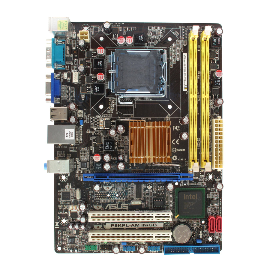
Page 11: Motherboard Overview
Motherboard overview 1.2.1 Motherboard layout Ensure that you install the motherboard into the chassis in the correct orientation. The edge with external ports goes to the rear part of the chassis. Place this side towards the rear of the chassis. Place six screws into the holes indicated by circles to secure the motherboard to the chassis. -
Page 12: Central Processing Unit (Cpu)
Contact your retailer immediately if the PnP cap is missing, or if you see any damage to the PnP cap/socket contacts/motherboard components. ASUS will shoulder the cost of repair only if the damage is shipment/transit-related. • Keep the cap after installing the motherboard. ASUS will process Return Merchandise Authorization (RMA) requests only if the motherboard comes with the cap on the LGA775 socket. - Page 13 • You may install varying memory sizes in Channel A and Channel B. The system maps the total size of the lower-sized channel for the dual-channel configuration. Any excess memory from the higher-sized channel is then mapped for single-channel operation. •...
- Page 14 Qimonda HY818T1G800C2F-2.5 • • Samsung K4T51083QG-HCF7 512MB Qimonda M378T6553GZS-CF7 • • Samsung K4T1G084QQ-HCF7 1024MB Qimonda M378T2863QZS-CF7 • • Samsung K4T51083QG-HCF7 1024MB Samsung M378T2953GZ3-CF7 • • Samsung K4T1G084QQ-HCF7 2048MB Samsung M37875663QZ3-CF7 • • (continued on the next page) ASUS P5KPL-AM IN/GB...
- Page 15 A*: Supports one module inserted into either slot as Single-channel memory configuration. • B*: Supports one pair of modules inserted into both the yellow slots as one pair of Dual-channel memory configuration. Visit the ASUS website at www.asus.com for the latest QVL. Chapter 1: Product introduction...
-
Page 16: Expansion Slots
• The USB device wake-up feature requires a power supply that can provide 500mA on the +5VSB lead for the USB port. Otherwise, the system will not power up. • The total current consumed must NOT exceed the power supply capability (+5VSB) whether under normal condition or in sleep mode. ASUS P5KPL-AM IN/GB... -
Page 17: Clear Rtc Ram
Clear RTC RAM (3-pin CLRTC) This jumper allows you to clear the Real Time Clock (RTC) RAM in CMOS. You can clear the CMOS memory of date, time, and system setup parameters by erasing the CMOS RTC RAM data. The onboard button cell battery powers the RAM data in CMOS, which include system setup information such as the system passwords. -
Page 18: Connectors
Refer to the table below for the LAN port LED indications. LAN port LED indications ACT/LINK SPEED Activity/Link LED Speed LED Status Description Status Description No link 10Mbps connection ORANGE Linked ORANGE 100Mbps connection BLINKING Data activity GREEN 1Gbps connection LAN port ASUS P5KPL-AM IN/GB... -
Page 19: Internal Connectors
Line In port (light blue). This port connects to the tape, CD, DVD player, or other audio sources. Line Out port (lime). This port connects to a headphone or a speaker. In 4-channel and 6-channel configuration, the function of this port becomes Front Speaker Out. Microphone port (pink). - Page 20 • If any device jumper is set to Cable-Select, ensure that all other device jumpers have the same setting. Speaker connector (4-pin SPEAKER) This 4-pin connector is for the chassis-mounted system warning speaker. The speaker allows you to hear system beeps and warnings. 1-11 ASUS P5KPL-AM IN/GB...
- Page 21 Only the CPU fan supports the ASUS Q-Fan feature. DO NOT forget to connect the CPU fan cable to the CPU fan connector. Insufficient air flow inside the system may damage the motherboard components.
- Page 22 These USB connectors comply with the USB 2.0 specification that supports up to 480Mbps data transmission speed. Never connect a 1394 cable to the USB connectors. Doing so will damage the motherboard! The USB module cable is purchased separately. 1-13 ASUS P5KPL-AM IN/GB...
-
Page 23: System Panel Connector
System panel connector (10-1 pin F_PANEL) This connector supports several chassis-mounted functions. • System power LED (2-pin PWRLED) This 2-pin connector is for the system power LED. Connect the chassis power LED cable to this connector. The system power LED lights up when you turn on the system, and blinks when the system is in sleep mode. -
Page 24: Software Support
The contents of the Support CD are subject to change at any time without notice. Visit the ASUS website at www.asus.com for updates. To run the Support CD Place the Support CD into the optical drive. -
Page 25: Chapter 2: Bios Information
BIOS in the future. Copy the original motherboard BIOS using the ASUS Update utility.. 2.1.1 ASUS Update utility The ASUS Update is a utility that allows you to manage, save, and update the motherboard BIOS in Windows environment. ®... -
Page 26: Asus Ez Flash 2 Utility
Follow the onscreen instructions to complete the updating process. 2.1.2 ASUS EZ Flash 2 utility The ASUS EZ Flash 2 feature allows you to update the BIOS without using an OS-based utility. Download the latest BIOS file from the ASUS website at www.asus.com. -
Page 27: Asus Crashfree Bios 3 Utility
2.1.3 ASUS CrashFree BIOS 3 utility The ASUS CrashFree BIOS 3 is an auto recovery tool that allows you to restore the BIOS file when it fails or gets corrupted during the updating process. You can update a corrupted BIOS file using the motherboard Support CD or a USB flash disk that contains the updated BIOS file. -
Page 28: Bios Setup Program
• The BIOS setup screens in this chapter are for reference only. They may not exactly match what you see on your screen. • Visit the ASUS website at www.asus.com to download the latest BIOS file for this motherboard. Main menu When you enter the BIOS Setup program, the Main menu screen appears, giving you an overview of the basic system information. -
Page 29: Storage Configuration
2.3.3 Primary IDE Master/Slave, SATA 1/2 While entering Setup, the BIOS automatically detects the presence of IDE/SATA devices. There is a separate submenu for each IDE/SATA device. Select a device item then press <Enter> to display the IDE/SATA device information. The BIOS automatically detects the values opposite the dimmed items (Device, Vendor, Size, LBA Mode, Block Mode, PIO Mode, Async DMA, Ultra DMA, and SMART monitoring). -
Page 30: System Information
[Overclock Profile] - Loads overclocking profiles with optimal parameters for stability when overclocking. [Test Mode] - Loads overclock (overclocking 5%) with spread spectrum. The following item appears only when you set the AI Overclocking item to [Manual]. ASUS P5KPL-AM IN/GB... - Page 31 CPU Frequency [xxx] Displays the frequency sent by the clock generator to the system bus and PCI bus. The value of this item is auto-detected by the BIOS. Use the <+> and <-> keys to adjust the CPU frequency. You can also key in the desired CPU frequency using the numeric keypad. The values range from 133 to 600.
-
Page 32: Usb Configuration
Enable this item to boot legacy operating systems that cannot support CPUs with extended CPUID functions. Configuration options: [Disabled] [Enabled] Vanderpool Technology [Enabled] Enable this item when the processor supports Vanderpool technology. Users need to reset the computer to change the configuration of this item. Configuration options: [Disabled] [Enabled] ASUS P5KPL-AM IN/GB... -
Page 33: Chipset
CPU TM function [Enabled] Enables or disables Intel CPU Thermal Monitor (TM2) function, a CPU overheating ® protection function. When this item is set to [Enabled], the CPU core frequency and voltage is reduced when the CPU overheats. Configuration options: [Enabled] [Disabled] Execute Disable Bit [Enabled] Allows you to Enable/disable Execute Disable Function. -
Page 34: Onboard Devices Configuration
When this item is set to [Enabled], the pallete snooping feature informs the PCI devices that an ISA graphics device is installed in the system so that the latter can function correctly. Configuration options: [Disabled] [Enabled] 2-10 ASUS P5KPL-AM IN/GB... -
Page 35: Power Menu
IRQ-xx assigned to [PCI Device] When set to [PCI Device], the specific IRQ is free for use of PCI/PnP devices. When set to [Reserved], the IRQ is reserved for legacy ISA devices. Configuration options: [PCI Device] [Reserved] Power menu The Power menu items allow you to change the settings for the Advanced Power Management (APM). -
Page 36: Apm Configuration
CPU Q-Fan Function [Disabled] Allows you to enable or disable the Q-Fan function. Configuration options: [Disabled] [Enabled] VCORE Voltage, 3.3V Voltage, 5V Voltage, 12V Voltage The onboard hardware monitor automatically detects the voltage output through the onboard voltage regulators. 2-12 ASUS P5KPL-AM IN/GB... -
Page 37: Boot Menu
POST items. Configuration options: [Disabled] [Enabled] Full Screen Logo [Enabled] This allows you to enable or disable the full screen logo display feature. Configuration options: [Disabled] [Enabled] Set this item to [Enabled] to use the ASUS MyLogo feature. ™ AddOn ROM Display Mode [Force BIOS] Sets the display mode for option ROM. -
Page 38: Security
[View Only] - allows access but does not allow change to any field. [Limited] - allows changes only to selected fields, such as Date and Time. [Full Access] - allows viewing and changing all the fields in the Setup utility. 2-14 ASUS P5KPL-AM IN/GB... -
Page 39: Tools Menu
3.CD-DISC (read only) 2.7.1 ASUS EZ Flash 2 Allows you to run ASUS EZ Flash 2. When you press <Enter>, a confirmation message appears. Use the left/right arrow key to select between [Yes] or [No], then press <Enter> to confirm your choice. -
Page 40: Exit Menu
When you select this option or if you press <F5>, a confirmation window appears. Select OK to load default values. Select Exit & Save Changes or make other changes before saving the values to the non-volatile RAM. 2-16 ASUS P5KPL-AM IN/GB...
Need help?
Do you have a question about the P5KPL-AM IN GB and is the answer not in the manual?
Questions and answers