Advertisement
Table of Contents
- 1 Table of Contents
- 2 Introduction
- 3 Guided Tour - SR55 Receiver Front Panel
- 4 Guided Tour - SR55 Receiver Rear Panel
- 5 Guided Tour - SR5 Receiver Front Panel
- 6 Guided Tour - SR5 Receiver Rear Panel
- 7 Guided Tour - ST5 Transmitter
- 8 Guided Tour - HT5 Transmitter
- 9 Setting up and Using Your Stage 55 Series/Stage 5 Series System
- 10 Appendix B: Carrying Case
- 11 Specifications
- Download this manual
See also:
Owner's Manual
Advertisement
Table of Contents

Related Manuals for Samson Stage 55


Summary of Contents for Samson Stage 55
- Page 1 T R U E D I V E R S I T Y W I R E L E S S S Y S T E M W I R E L E S S S Y S T E M...
-
Page 2: Table Of Contents
Guided Tour - SR5 Receiver Rear Panel Guided Tour - ST5 Transmitter Guided Tour - HT5 Transmitter Setting Up and Using Your Stage 55 Series / Stage 5 Series System Appendix B: Carrying Case Specifications Copyright 2002, Samson Technologies Corp. -
Page 3: Introduction
(for lavaliere microphone or headset applications); a ST5 belt-pack transmitter (for instrument applications); or a HT5 hand-held microphone transmitter. For convenience and security, the Stage 55 Series and Stage 5 Series system is packaged in a custom impact-resistant polypropylene plastic carrying case that provides room for all components (see Appendix B for more information). - Page 4 Introduction In this manual, you’ll find a more detailed description of the features of your Stage 55 Series or Stage 5 Series system, as well as a guided tour through all components, step- by-step instructions for setting up and using your system and full specifications. If your Stage 55 Series or Stage 5 Series system was purchased in the United States, you’ll also...
-
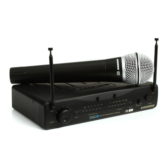
Page 5: Guided Tour - Sr55 Receiver Front Panel
(the antenna on the right) should be placed in a vertical position. Both antennas can be folded inward for convenience when transporting the SR55. See the “Setting Up and Using Your Stage 55 Series / Stage 5 Series System” section on page 12 in this manual for more information about antenna positioning. -
Page 6: Guided Tour - Sr55 Receiver Rear Panel
(see #4 below) to -20 dBm (line level) or -40 dBm (mic level). See the “Setting Up and Using Your Stage 55 Series / Stage 5 Series System” section on page 12 in this manu- al for more information. -
Page 7: Guided Tour - Sr5 Receiver Front Panel
When only the left-most “-20” segment is lit, the incoming signal is at just 10% of optimum strength. If no segments are lit, little or no signal is being received. See the “Setting Up and Using Your Stage 55 Series / Stage 5 Series System” section on page 12 in this manu- al for more information. -
Page 8: Guided Tour - Sr5 Receiver Rear Panel
(see #4 below) to -20 dBm (line level) or -40 dBm (mic level). See the “Setting Up and Using Your Stage 55 Series / Stage 5 Series System” section on page 10 in this man- ual for more information. -
Page 9: Guided Tour - St5 Transmitter
Guided Tour - SR5 / ST5 HIGH B AT T E RY L E V E L AUDIO ON 1: Input connector - The input device is connected here. The ST5 is supplied with either a lavaliere, headset microphone or heavy-duty instrument cable terminating with a 1/4" plug, which are all connected to the transmitter via a locking 3.5mm mini-phone jack. - Page 10 9: Plastic screwdriver - Specially designed for use in adjusting the ST5 Gain control (see #7 above) and/or receiver Squelch control (see #4 on pages 5 and 7). See the “Setting Up and Using Your Stage 55 Series / Stage 5 Series System” section on page 12 in this manu- al for more information.
-
Page 11: Guided Tour - Ht5 Transmitter
Stage 55 Series or Stage 5 Series system and so we recommend that this not be adjusted manually. If necessary, however, you can use the supplied plastic screw- driver to raise or lower the input level. -
Page 12: Setting Up And Using Your Stage 55 Series/Stage 5 Series System
The basic procedure for setting up and using your Stage 55 Series or Stage 5 Series Wireless System takes only a few minutes: 1. For the Stage 55 Series / Stage 5 Series system to work correctly, both the receiver and transmitter must be set to the same channel. Remove all packing materials (save them in case of need for future service) and check to make sure that the supplied receiver and transmitter are set to the same channel. - Page 13 Setting Up and Using Your Stage 55 Series/Stage 5 Series System 9. Now it’s time to set the audio levels. Turn on your connected amplifier and/or mixer but keep its volume all the way down. Next, make sure that your transmitter is unmuted by setting its Audio switch to “On.”...
- Page 14 “Min” position (so as to have the greatest overall range available). 13. When first setting up the Stage 55 Series or Stage 5 Series System in a new environ- ment, it’s always a good idea to do a walkaround in order to make sure that coverage is provided for your entire performance area.
-
Page 15: Appendix B: Carrying Case
Appendix A: Carrying Case To ensure the longevity of your Stage 55 Series / Stage 5 Series system, and for conve- nience when on the road, your Stage 55 Series / Stage 5 Series system includes an impact-resistant polypropylene plastic carrying case with foam rubber padding. As shown in the illustration below, custom cutouts in the interior padding provide secure placement for all components in your system. -
Page 16: Specifications
Specifications Transmitter (ST5 and HT5): Transmission Mode Frequency modulation, 80KF3E, 15 kHz peak deviation Frequency Range 173.80 MHz to 213.20 MHz, 25 frequencies Band A (European / UK models) 160.10 to 177.90 MHz Band B (European / UK models) 189.10 to 210.10 MHz OSC System Crystal controlled, x12 multiplication RF Power... - Page 17 FCC Rules and Regulations Samson wireless systems are type accepted under FCC rules parts 90, 74 and 15. Licensing of Samson equipment is the user’s responsibility and licensability depends on the user’s classification, application and frequency selected. This device complies with RSS-210 of Industry &...
Need help?
Do you have a question about the Stage 55 and is the answer not in the manual?
Questions and answers