Sign In
Upload
Manuals
Brands
Teledyne Manuals
Analytical Instruments
4060 Series
Teledyne 4060 Series Manuals
Manuals and User Guides for Teledyne 4060 Series. We have
1
Teledyne 4060 Series manual available for free PDF download: Instruction, Operating And Maintenance Manual
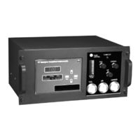
Teledyne 4060 Series Instruction, Operating And Maintenance Manual (79 pages)
Trace Aromatic Hydrocarbon Analyzer
Brand:
Teledyne
| Category:
Analytical Instruments
| Size: 0.97 MB
Table of Contents
Safety Messages
3
Additional Safety Information
5
Table of Contents
9
List of Figures
13
List of Tables
15
Introduction
15
Main Features of the Analyzer
15
Principle of Operation
16
Analyzer Description
16
Figure 1-1: Model 4060 Front Panel Interface
17
Figure 1-2: Model 4060 Rear Panel
17
Applications
18
Operational Theory
19
Introduction
19
Modes of Operation
19
Analyzer Subsystems
20
Sample System
20
Gas Flow Control System
21
Figure 2-1: Internal Temperature Controllers
21
Fuel and Blanket Air Systems
22
Flame Ionization Detection Cell
22
Figure 2-2: Typical Piping Diagram for the Model 4060
23
Detection Cell
24
Electrometer-Amplifier
25
Anode Power Supply
26
Flame Guard Circuit
26
Flame Ignition Circuit
26
Installation
27
Unpacking the Analyzer
27
Mounting the Analyzer
27
Series
27
User Connections
28
Electrical Power Connections
28
Electronic Connections
28
Primary Input Power
29
Figure 3-1: Model 4060 Rear Panel with Optional Gas Manifold
29
Fuse Installation
30
50-Pin Equipment Interface Connector
30
Analog Output
30
Figure 3-2: Equipment Interface Connector Pin Arrangement
30
Table 3-1: Analog Output Connections
31
Table 3-2: Analog Concentration Output-Example
31
Alarm Relays
32
Table 3-3: Analog Range ID Output-Example
32
Table 3-4: Alarm Relay Contact Pins
33
Digital Remote Cal Inputs
34
Table 3-5: Remote Calibration Connections
34
Range ID Relays
35
Network I/O
35
Pin out Table
35
Table 3-6: Range ID Relay Connections
35
RS-232 Port
36
Table 3-7: Pin out of 50 Pin D-Sub Connector
36
Gas Connections
37
Table 3-8: Commands Via RS-232 Input
37
Table 3-9: Required RS-232 Options
37
Effluent
40
Fuel and Air Connections
40
Sample and Span Gas Connections
40
Sample Bypass Vent
40
Placing the System in Operation
40
Operation
41
Equipment
41
Preliminary Power-Off Check List
42
Activating the Support Gases
42
Air
43
Carrier Gas
43
Span Gas
43
Fuel
43
Flame Ignition
43
Verification of the Flame Guard Circuit
44
Ignition And/Or Flame Guard Circuit Failure
44
Series
44
Sample Pump
44
Analyzer Operation
44
Default Parameters
46
Style Conventions
46
Navigation and Data Entry
47
Arrow Keys
47
Enter
47
Escape
48
Menu Structure
48
Main Menus
49
Span
50
Alt-Span
51
The Model Screen
51
System Self-Diagnostic Test
51
The Alarms Function
52
The Range Function
55
Analog Output Adjustment
55
Linearization
56
Changing Stream
56
Setting up an AUTO-CAL
56
Timing
58
Group Setup
58
Password Protection
58
Logging out
61
Standby
62
Maintenance & Troubleshooting
65
Measuring Circuit Electrical Checks
66
Anode Voltage Check
66
Electronic Stability
67
Printed Circuit Board Replacement
67
Series
67
Collector Cable
68
Temperature Control Electronic Check
68
Ignition And/Or Flame Guard Circuit Checks
69
Sampling System
70
Printed Circuit Board Descriptions
71
Flame Guard and Anode Power Supply PCB
71
Proportional Temperature Controller PCB
72
Electrometer-Amplifier PCB
73
Appendix
75
Specifications and Initial Settings
75
Recommended Spare Parts List
76
Drawing List
77
Appendix B
79
B1 Addendum and Testing Results
79
Advertisement
Advertisement
Related Products
Teledyne 402R-EU
Teledyne 4020
Teledyne 4030 Series
Teledyne 4040
Teledyne 400E
Teledyne 401
Teledyne Linea 4k CL
Teledyne DALSA Piranha 4 Color
Teledyne 4250
Teledyne 440
Teledyne Categories
Measuring Instruments
Analytical Instruments
Digital Camera
Test Equipment
Security Camera
More Teledyne Manuals
Login
Sign In
OR
Sign in with Facebook
Sign in with Google
Upload manual
Upload from disk
Upload from URL