Sign In
Upload
Manuals
Brands
Teledyne Manuals
Analytical Instruments
4020
Teledyne 4020 Manuals
Manuals and User Guides for Teledyne 4020. We have
1
Teledyne 4020 manual available for free PDF download: Operating & Maintenance Manual
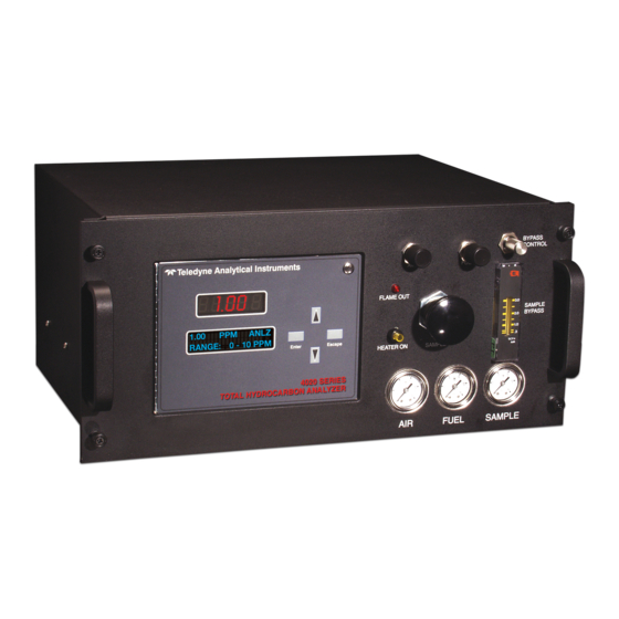
Teledyne 4020 Operating & Maintenance Manual (100 pages)
Total Hydrocarbon Analyzer
Brand:
Teledyne
| Category:
Analytical Instruments
| Size: 1.39 MB
Table of Contents
Safety Messages
5
Table of Contents
7
List of Figures
12
List of Tables
14
Additional Safety Information
14
Procedure for Removal of Internal Inaccessible Shock Hazards
16
Introduction
19
Main Features of the Analyzer
19
Principle of Operation
20
Analyzer Description
20
Applications
21
Figure 1-1: Gas Sample System with Optional Autocal Valves
22
Figure 1-2: Gas Sample System Without Optional Autocal Valves
23
Figure 1-3: Flame Ionization Cell
24
Operational Theory
25
Introduction
25
Sample System
25
Input Porting
26
Sample Flow Control System
26
Fuel and Blanket Air Systems
27
Flame Ionization Detection Cell
27
Detection Cell
27
Electrometer-Amplifier
29
Anode Power Supply
29
Figure 2-1: View Inside Cabinet
29
Flame Guard Circuit
30
Flame Ignition Circuit
30
Proportional Temperature Control Circuit
30
Installation
31
Unpacking the Analyzer
31
Model
31
Mounting the Analyzer
31
User Connections
32
Electrical Power Connections
32
Gas Connections
32
Figure 3-1: Gas Connections
33
Vent Connections
34
Electrical Connections
35
Primary Input Power
35
Fuse Installation
35
50-Pin Equipment Interface Connector
35
Analog Output
36
Figure 3-2: Equipment Interface Connector Pin Arrangement
36
Table 3-1: Analog Output Connections
36
Table 3-2: Analog Concentration Output-Example
37
Alarm Relays
38
Table 3-3: Analog Range ID Output-Example
38
Background Gas Selection and Digital Remote Cal Inputs
39
Table 3-4: Alarm Relay Contact Pins
39
Table 3-5: Remote Calibration Connections
40
Range ID Relays
41
Network I/O
41
Pin out Table
41
Table 3-6: Range ID Relay Connections
41
Table 3-7: Pin out of 50 Pin D-Sub Connector
41
Port
43
Table 3-8: Commands Via RS-232 Input
43
Supporting Gases
44
Table 3-9: Required RS-232 Options
44
Effluent
45
Fuel and Air Connections
45
Sample Bypass Vent
45
Sample Gas
45
Operation
47
Equipment
47
Preliminary Power-Off Check List
48
Placing the System in Operation
48
Activating the Support Gases
49
Air
49
Sample Gas
49
Span Gas
49
Fuel
49
Flame Ignition
50
Verification of the Flame Guard Circuit
50
Figure 4-1: Front Panel View of Regulator and Gages
50
Ignition And/Or Flame Guard Circuit Failure
51
Analyzer Operation
51
Default Parameters
52
Style Conventions
53
Using the Controls
53
Figure 4-2: Typical VFD Screen Layout
53
Mode/Function Selection
54
Analysis Mode
54
Setup Mode
55
Data Entry
56
Enter
56
Figure 4-3: Setup Mode Functions
57
Escape
58
Setting up an AUTO-CAL
58
Password Protection
60
Figure 4-4: AUTOCAL Screens
60
Entering the Password
61
Installing or Changing the Password
62
Logging out
63
System Self-Diagnostic Test
63
The Model Screen
64
Zero and Span Functions
65
The Alarms Function
68
The Range Function
71
Manual (Select/Define Range) Screen
71
Auto Range
73
Digital Filter Setup
74
Fuel Display
75
Valve Selections
75
Disabled
76
Model
76
User Select
76
Default (by Function)
77
Observing the Gas Stream Concentrations
79
Standby
80
Advanced User Functions
80
Zero Offset Adjustment
80
Background Gas Selection
81
Manually Selecting a Background Gas
82
Automatic Background Gas Selection
83
Match/Invert
83
Table 4-2: AL-2 Relay Status for MATCH and INVERT
84
Maintenance & Troubleshooting
85
Measuring Circuit Electrical Checks
86
Loss of Zero Control
86
Anode Voltage Check
87
Electronic Stability
88
Printed Circuit Board Replacement
88
Collector Cable
88
Temperature Control Electronic Check
89
Ignition And/Or Flame Guard Circuit Checks
90
Sampling System
91
Printed Circuit Board Descriptions
91
Flame Guard and Anode Power Supply PCB
91
Proportional Temperature Controller PCB
92
Electrometer-Amplifier PCB
94
Appendix
98
Appendix
98
Application Data
98
Recommended Spare Parts List
99
Drawing List
100
Advertisement
Advertisement
Related Products
Teledyne 402R-EU
Teledyne 4030 Series
Teledyne 4040
Teledyne 4060 Series
Teledyne 400E
Teledyne 401
Teledyne 460H NEMA
Teledyne 4220
Teledyne 452
Teledyne PINNACLE 45
Teledyne Categories
Measuring Instruments
Analytical Instruments
Digital Camera
Test Equipment
Security Camera
More Teledyne Manuals
Login
Sign In
OR
Sign in with Facebook
Sign in with Google
Upload manual
Upload from disk
Upload from URL