Sign In
Upload
Manuals
Brands
Omron Manuals
Controller
E5*D series
Omron E5*D series Manuals
Manuals and User Guides for Omron E5*D series. We have
2
Omron E5*D series manuals available for free PDF download: User Manual, Connection Manual
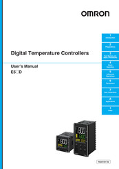
Omron E5*D series User Manual (404 pages)
Digital Temperature Controllers
Brand:
Omron
| Category:
Controller
| Size: 40.05 MB
Table of Contents
Preface
3
Terms and Conditions Agreement
4
Application Considerations
5
Disclaimers
5
Safety Precautions
6
Definition of Precautionary Information
6
Symbols
6
Precautions for Safe Use
9
Precautions for Correct Use
12
Preparations for Use
14
Versions
15
Revision History
16
H224-E1
16
Conventions Used in this Manual
17
Model Notation
17
Meanings of Abbreviations
17
Terminology
17
How to Read Display Symbols
18
How this Manual Is Organized
18
Related Manuals
18
Introduction
18
Sections in this Manual
19
Table of Contents
20
Introduction
25
Section 1 Introduction
26
Appearance, Features, and Functions of the E5@D
26
Appearance
26
Features
26
Main Functions
29
I/O Configuration and Model Number Legend
31
I/O Configuration
31
Model Number Legends
32
Preparations
41
Section 2 Preparations
42
Installation
42
Dimensions (Unit: MM)
42
Panel Cutout (Unit: MM)
44
Mounting
45
Drawing out the Interior Body of the Digital Controller to Replace It
47
Using the Terminals
49
E5CD Terminal Block Wiring Example
49
E5CD-B Terminal Block Wiring Example
53
E5ED Terminal Block Wiring Example
57
E5ED-B Terminal Block Wiring Example
61
Precautions When Wiring
65
Wiring
68
Installing Temperature Sensors for Packing Machines
76
Insulation Block Diagrams
78
Using the Setup Tool Port
79
Procedure
79
Connection Method
79
Installing the Driver
82
Part Names and Basic Procedures
83
Basic Flow of Operation
84
Power on
85
Part Names, Part Functions, and Setting Levels
86
Part Names and Functions
86
Entering Numeric Values
89
Setting Levels
90
Procedures after Turning on the Power Supply
93
Basic Flow of Operations
93
Basic Procedure
93
Basic Operation
101
Moving between Setting Levels
103
Moving to the Initial Setting Level
103
Moving to the Adjustment Level
104
Moving to the Protect Level
104
Moving to the Advanced Function Setting Level
105
Moving to the Communications Setting Level
107
Initial Setting Examples
108
Setting the Input Type
111
Input Type
111
Selecting the Temperature Unit
113
Temperature Unit
113
Selecting PID Control or ON/OFF Control
114
Setting Output Specifications
115
Control Period
115
Direct and Reverse Operation
115
Assigned Output Functions
116
Auxiliary Output Opening or Closing in Alarm
119
Setting the Set Point (SP)
120
Changing the SP
120
Using ON/OFF Control
121
ON/OFF Control
121
Settings
122
Determining PID Constants (AT, Manual Setup)
124
AT (Auto-Tuning)
124
RT (Robust Tuning) (Use with AT)
127
Manual Setup
129
Alarm Outputs
131
Alarm Types
131
Alarm Values
134
Alarm Hysteresis
137
Standby Sequence
137
Alarm Latch
138
Using Heater Burnout (HB) and Heater Short (HS) Alarms
139
HB Alarm
139
HS Alarm
141
Installing Current Transformers (CT)
143
Calculating Detection Current Values
144
Application Examples
144
Customizing the PV/SP Display
146
PV/SP Display Selections
146
Advanced Operations 7
147
Section 5 Advanced Operations
149
Suppressing Temperature Variations When Using a Temperature Sensor for Packing Machines (for Packing Machines)
149
Automatically Adjusting a Water-Cooling Output (for Water-Cooled Extruders)
153
Automatically Adjusting a Water-Cooling Output
153
Performing Adaptive Control
157
Overview
157
Application Methods for Adaptive Control
165
Indication Data
167
Shifting Input Values
171
Setting Scaling Upper and Lower Limits for Analog Inputs
173
Executing Heating/Cooling Control
175
Heating/Cooling Control
175
Using Event Inputs
179
Event Input Settings
179
How to Use the Multi-SP Function
179
Operation Commands Other than Multi-SP
181
Setting the SP Upper and Lower Limit Values
185
Set Point Limiter
185
Setting
186
Using the SP Ramp Function to Limit the SP Change Rate
187
SP Ramp
187
Using the Key Protect Level
189
Protection
189
Entering the Password to Move to the Protect Level
190
Hiding and Displaying Parameters
192
Parameter Mask Setting
192
OR Output of Alarms
195
Integrated Alarm
195
Alarm Delays
197
Loop Burnout Alarm
199
Loop Burnout Alarm (LBA)
199
Performing Manual Control
202
Manual MV
202
Using the Simple Program Function
205
Simple Program Function
205
Operation at the Program End
208
Application Example Using a Simple Program
210
Output Adjustment Functions
211
Output Limits
211
MV at Stop
211
MV at PV Error
211
Using the Extraction of Square Root Parameter
213
Extraction of Square Roots
213
Setting the Width of MV Variation
215
MV Change Rate Limit
215
Setting the PF Key
216
PF Setting (Function Key)
216
Displaying PV/SV Status
219
PV and SV Status Display Functions
219
Logic Operations
221
The Logic Operation Function (CX-Thermo)
221
Using Logic Operations
221
Initializing Settings
230
Setting the Operating Status to Use When Power Is Turned on
231
Using the Transfer Output for the Process Value, Set Point, or Other Data
232
Transfer Output Function
232
Conventions Used in this Section
236
Protect Level
237
Operation Level
241
Adjustment Level
250
Monitor/Setting Item Level
271
Manual Control Level
272
Initial Setting Level
274
Advanced Function Setting Level
296
Communications Setting Level
331
User Calibration
335
User Calibration
336
7-1 User Calibration
337
Parameter Structure
337
Thermocouple Calibration
338
Resistance Thermometer Calibration
341
Calibrating Analog Input
343
Calibrating the Transfer Output
347
Checking Indication Accuracy
349
Appendices
353
Section a Appendices
354
Specifications
354
A-1-1 Ratings
354
A-1-2 Characteristics
356
A-1-3 Rating and Characteristics of Options
357
A-1-4 Waterproof Packing
357
Setup Tool Port Cover for Front Panel
358
A-1-6 Draw-Out Jig
359
Current Transformer (CT
360
A-2-1 Specifications
360
A-2-2 Dimensions (Unit: MM
360
USB-Serial Conversion Cable and Conversion Cable
363
A-3-1 E58-CIFQ2 USB-Serial Conversion Cable
363
A-3-2 E58-CIFQ2-E Conversion Cable
364
Temperature Sensor for Packing Machines
365
A-4-1 Model Number Legend
365
A-4-2 Dimensions
366
A-4-3 Mounting Brackets
367
Error Displays
368
Troubleshooting
372
Parameter Operation Lists
375
A-7-1 Operation Level
375
A-7-2 Adjustment Level
376
A-7-3 Initial Setting Level
378
A-7-4 Manual Control Level
382
A-7-5 Monitor/Setting Item Level
382
A-7-6 Advanced Function Setting Level
382
A-7-7 Protect Level
387
A-7-8 Communications Setting Level
387
A-7-9 Initialization According to Parameter Changes
388
Sensor Input Setting Range, Indication Range, Control Range
391
A-9 Setting Levels Diagram
392
A-10 Parameter Flow
395
A-11 Parameter Flow (for E5@D-@-80@)
395
Index
397
Advertisement
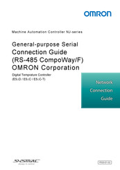
Omron E5*D series Connection Manual (60 pages)
General-purpose Serial. RS-485 CompoWay/F. Machine Automation Controller,
Brand:
Omron
| Category:
Controller
| Size: 2.66 MB
Table of Contents
Table of Contents
3
1 Related Manuals
4
2 Terms and Definitions
4
3 Precautions
5
4 Overview
6
5 Applicable Devices and Device Configuration
7
Applicable Devices
7
Device Configuration
9
6 Serial Communications Settings
11
Parameters
11
Cable Wiring
12
7 Serial Communications Connection Procedure
13
Work Flow
13
Digital Temperature Controller Setup
14
Controller Setup
18
Serial Communication Status Check
33
8 Initialization Method
35
Initializing a Controller
35
Initializing a Digital Temperature Controller
36
9 Program
37
Overview
37
Destination Device Command
43
Error Detection Processing
46
Variables
47
ST Program
49
Timing Charts
54
Error Processing
55
10 Revision History
59
Advertisement
Related Products
Omron E5DC-*****M-002 Series
Omron E5DC-*****M-015 Series
OMRON E5ER-T
Omron E53-CKB
Omron E5CD
Omron E5ED-**4**M-004 Series
Omron E5AC-*****SM-009 Series
Omron E5CC-T**3*SM-003 Series
Omron E5EC-T**4*SM-004 Series
Omron E5AX-MA
Omron Categories
Blood Pressure Monitor
Controller
Accessories
Switch
Inverter
More Omron Manuals
Login
Sign In
OR
Sign in with Facebook
Sign in with Google
Upload manual
Upload from disk
Upload from URL